CAMPAGNOLO EPS V4 User manual

COMPONENTS
INSTALLATION OF THE INTERFACE UNIT V4 (INTERNAL)
INSTALLATION - Rev. 00/ 06-2019 1
WARNING!
THIS TECHNICAL MANUAL IS INTENDED FOR USE BY PROFESSIONAL MECHANICS.
Anyone who is not professionally qualied to assemble bicycles should not attempt to install and operate on the components because of the risk of carrying out incor-
rect operations that could cause the components to malfunction with the consequent risk of accidents, physical injury or even death.
The actual product may dier from what is illustrated, as the specic purpose of these instructions is to explain the procedures for using the component.
1 – COMPATIBILITY
WARNING!
This Interface Unit V4 is not compatible with Bar-End controls or Bar-End brake controls.
2 - INTERFACE WITH THE FRAME
2.1 - SPECIFICATIONS FOR FRAME INSTALLATION
Note: where not specied, all measurements are expressed in millimetres.
15,3
9
3,5
27
Ø 19
27,6
49
35,5
M3
36
1

COMPONENTS
INSTALLATION - Rev. 00/ 06-20192
2.2 - SPECIFICATIONS FOR HANDLEBAR INSTALLATION
If the internal V4 interface is installed inside the handlebar, the latter must comply with the following specications:
1) Inner diameter of the handlebar, right-hand side, with a length from the edge of 49 mm min.: 19 - 22.5 mm (Fig.2)
2) Presence of two holes to enable the connectors (which are to be connected to the controls and the power unit) to come out of
the handlebar: specications regarding the size of the holes and their position (Fig.2).
3) There must be a hole inside the handlebar with a minimum diameter of 8 mm along its entire length. This is used to pass the con-
nector and the corresponding wiring to be connected to the left-hand control from the right-hand side of the handlebar to the left,
where the interface is to be positioned.
49 mm Min.
49 mm Min.
49 mm Min.
8.5 mm Min.
8.5 mm Min.
8.5 mm Min.
19-22.5 mm Min.
20
Ø 28
2

Code Description
UT-GC010EPS Cable guide magnet kit
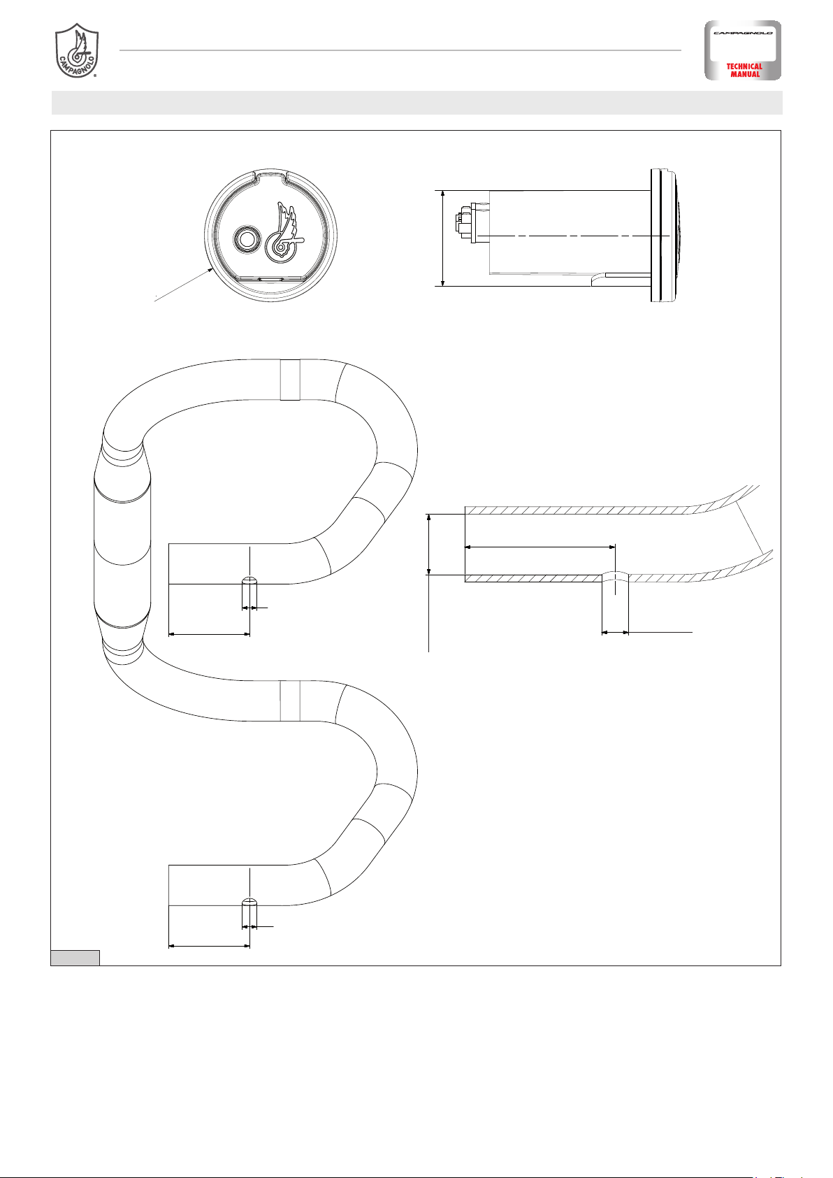
COMPONENTS
INSTALLATION - Rev. 00/ 06-2019 3
3 - INSTALLING THE INTERFACE UNIT V4
3.1 - TOOLS AND ACCESSORIES
3.2 - HANDLEBAR INSTALLATION
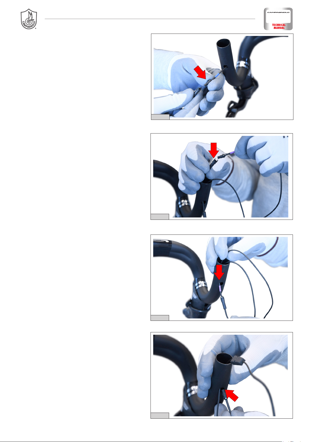
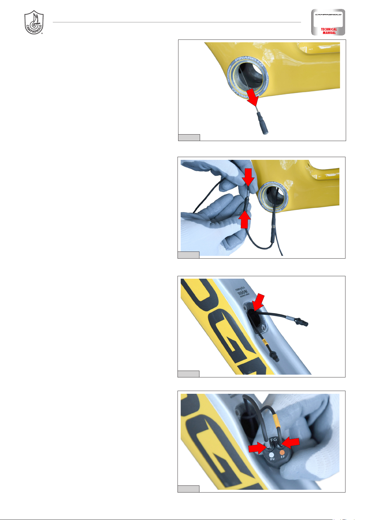
1) Insert the long cable from the “cable guide magnet
kit” into the lower left-hand hole on the handlebar
(Fig.1).
2) Bring the cable out from the right-hand side of
the handlebar, using the short cable from the “cable
guide magnet kit” to help if necessary (Fig. 2).
3) Connect the short cable from the “cable guide
magnet kit” to the long cable, and complete the con-
nection with the left-hand wiring connector (asym-
metrical) (Fig. 3).
2
3
1

COMPONENTS
INSTALLATION - Rev. 00/ 06-20194
4) At this point, bring the left-hand wiring connector
out from the lower left-hand hole (Fig. 4).
5) Insert the short cable from the “cable guide mag-
netic kit” into the lower right-hand hole on the han-
dlebar, connect the right-hand control connector (Fig.
5) and bring it out from the same hole (Fig. 6).
6) Insert the single connection cable to the power
unit into the lower right-hand hole. (Fig. 7).
WARNING! Ensure that you have inserted the
male connector.
4
5
6
7

COMPONENTS
INSTALLATION - Rev. 00/ 06-2019 5
7) Bring the single connection cable out from the
right-hand side of the handlebar (Fig. 8).
8) Rest the cover (A) on the ring (B) and insert the tab
(C) inside (in correspondence with the flat part of the
ring) (Fig. 9).
9
9) Move this assembly (A+B) next to the interface,
insert the ring (D) from the rear side and slide it along
the interface. At this point, insert the tab (C) inside
the ring, in correspondence with the tab (E) (Fig. 10).
10
10) Line up the teeth on the ring (B) with the holes in
the ring (D) and rotate the latter until the two rings (B
and D) are attached to one another (Fig. 11).
AB
C
A + B
ED
11
B
D
holes
teeth

COMPONENTS
INSTALLATION - Rev. 00/ 06-20196
11) Connect the control connectors to the controls
and position the cables on the handlebar, securing in
place with the adhesive tape (Fig. 12).
12) We recommend passing the cables from the inner
hole on the handlebar to the control area, along the
internal surface of the handlebar (Fig. 13 - Fig. 14).
13) Apply the handlebar tape flush with the edge,
without folding inwards (Fig. 15).
12
13
14
15

COMPONENTS
INSTALLATION - Rev. 00/ 06-2019 7
14) Apply the neoprene spacer on three surfaces of
the interface, beginning with the flat lower surface
(Fig. 16).
15) Insert the cable separator into the handlebar,
using a non-pointed tool to help (Fig.17).
17) Insert the interface into the handlebar (Fig. 19).
16) Connect the interface to the two cables and
match the cable colours with those on the interface
connectors (Fig. 18).
16
17
18
19

COMPONENTS
18) Check that the handlebar tape allows the inter-
face cover to be opened (Fig. 20).
20
3.3 - FRAME INSTALLATION
1) Remove the protective cover by unscrewing the
two screws (Fig. 1).
1
2) Insert the long cable from the “cable guide magnet
kit” into the housing hole on the frame (Fig. 2).
2
3) Bring the cable out from the hole near the han-
dlebar, using the short cable from the “cable guide
magnet kit” to help if necessary (Fig. 3).
3
INSTALLATION - Rev. 00/ 06-20198

COMPONENTS
4) Connect the orange connector to the “cable guide
magnet kit” and bring it out from the frame (Fig. 4).
5) Important! The bifurcation of the connector cables
for the controls must be positioned on the handlebar
(Fig. 5 - Fig. 6).
6) Insert the long cable from the “cable guide magnet
kit” from the interface housing hole (Fig. 7).
INSTALLATION - Rev. 00/ 06-2019 9
4
5
6
7

COMPONENTS
INSTALLATION - Rev. 00/ 06-201910
7) At this point, bring the long cable from the “cable
guide magnet kit” out from the bottom bracket (Fig.
8).
8) Connect the short cable from the “cable guide
magnet kit” and the grey interface cable (Fig. 9).
10) Insert the two male connectors into their cor-
responding female connectors (grey and orange);
these can be found inside the interface (Fig. 11).
9) Bring the connector out through the interface
housing hole (Fig. 10).
8
9
10
11

COMPONENTS
INSTALLATION - Rev. 00/ 06-2019 11
11) Insert the interface into the frame (Fig. 12).
12) Rest the cover (A) on the plate (B) and insert the
tab (C) inside the plate. (Fig. 13).
14) Fix the assembly to the frame, using the two
screws provided (Fig. 15).
13) Rest this assembly (cover + plate) on the frame,
checking that the cover tab is positioned correctly on
the underside of the interface, using a screwdriver to
help if necessary (Fig. 14).
12
13
15
14
A
B
C
Table of contents