Campbell CM106B User manual

I
NS
TR
UC
TI
ON
MA
NU
AL
CM106B Tripod
Revision: 7/14
Copyright © 2005-2014
Campbell Scientific, Inc.


PLEASE READ FIRST
About this manual
Please note that this manual was originally produced by Campbell Scientific Inc. (CSI) primarily
for the US market. Some spellings, weights and measures may reflect this origin.
Some useful conversion factors:
Area: 1 in2(square inch) = 645 mm2
Length: 1 in. (inch) = 25.4 mm
1 ft (foot) = 304.8 mm
1 yard = 0.914 m
1 mile = 1.609 km
Mass: 1 oz. (ounce) = 28.35 g
1 lb (pound weight) = 0.454 kg
Pressure: 1 psi (lb/in2) = 68.95 mb
Volume: 1 US gallon = 3.785 litres
In addition, part ordering numbers may vary. For example, the CABLE5CBL is a CSI part
number and known as a FIN5COND at Campbell Scientific Canada (CSC). CSC Technical
Support will be pleased to assist with any questions.
About sensor wiring
Please note that certain sensor configurations may require a user supplied jumper wire. It is
recommended to review the sensor configuration requirements for your application and supply the jumper
wire is necessary.

Precautions
DANGER — MANY HAZARDS ARE ASSOCIATED WITH INSTALLING, USING, MAINTAINING, AND WORKING ON OR AROUND
TRIPODS, TOWERS, AND ANY ATTACHMENTS TO TRIPODS AND TOWERS SUCH AS SENSORS, CROSSARMS, ENCLOSURES,
ANTENNAS, ETC. FAILURE TO PROPERLY AND COMPLETELY ASSEMBLE, INSTALL, OPERATE, USE, AND MAINTAIN TRIPODS,
TOWERS, AND ATTACHMENTS, AND FAILURE TO HEED WARNINGS, INCREASES THE RISK OF DEATH, ACCIDENT, SERIOUS
INJURY, PROPERTY DAMAGE, AND PRODUCT FAILURE. TAKE ALL REASONABLE PRECAUTIONS TO AVOID THESE HAZARDS.
CHECK WITH YOUR ORGANIZATION'S SAFETY COORDINATOR (OR POLICY) FOR PROCEDURES AND REQUIRED PROTECTIVE
EQUIPMENT PRIOR TO PERFORMING ANY WORK.
Use tripods, towers, and attachments to tripods and towers only for purposes for which they are designed. Do not exceed design
limits. Be familiar and comply with all instructions provided in product manuals. Manuals are available at www.campbellsci.com or
by telephoning 435-227-9000 (USA). You are responsible for conformance with governing codes and regulations, including safety
regulations, and the integrity and location of structures or land to which towers, tripods, and any attachments are attached. Installation
sites should be evaluated and approved by a qualified engineer. If questions or concerns arise regarding installation, use, or
maintenance of tripods, towers, attachments, or electrical connections, consult with a licensed and qualified engineer or electrician.
General
x Prior to performing site or installation work, obtain required approvals and permits. Comply
with all governing structure-height regulations, such as those of the FAA in the USA.
x Use only qualified personnel for installation, use, and maintenance of tripods and towers, and
any attachments to tripods and towers. The use of licensed and qualified contractors is
highly recommended.
x Read all applicable instructions carefully and understand procedures thoroughly before
beginning work.
x Wear a hardhat and eye protection, and take other appropriate safety precautions while
working on or around tripods and towers.
x Do not climb tripods or towers at any time, and prohibit climbing by other persons. Take
reasonable precautions to secure tripod and tower sites from trespassers.
x Use only manufacturer recommended parts, materials, and tools.
Utility and Electrical
x You can be killed or sustain serious bodily injury if the tripod, tower, or attachments you are
installing, constructing, using, or maintaining, or a tool, stake, or anchor, come in contact
with overhead or underground utility lines.
x Maintain a distance of at least one-and-one-half times structure height, or 20 feet, or the
distance required by applicable law, whichever is greater, between overhead utility lines and
the structure (tripod, tower, attachments, or tools).
x Prior to performing site or installation work, inform all utility companies and have all
underground utilities marked.
x Comply with all electrical codes. Electrical equipment and related grounding devices should
be installed by a licensed and qualified electrician.
Elevated Work and Weather
x Exercise extreme caution when performing elevated work.
x Use appropriate equipment and safety practices.
x During installation and maintenance, keep tower and tripod sites clear of un-trained or non-
essential personnel. Take precautions to prevent elevated tools and objects from dropping.
x Do not perform any work in inclement weather, including wind, rain, snow, lightning, etc.
Maintenance
x Periodically (at least yearly) check for wear and damage, including corrosion, stress cracks,
frayed cables, loose cable clamps, cable tightness, etc. and take necessary corrective actions.
x Periodically (at least yearly) check electrical ground connections.
WHILE EVERY ATTEMPT IS MADE TO EMBODY THE HIGHEST DEGREE OF SAFETY IN ALL CAMPBELL SCIENTIFIC PRODUCTS,
THE CUSTOMER ASSUMES ALL RISK FROM ANY INJURY RESULTING FROM IMPROPER INSTALLATION, USE, OR
MAINTENANCE OF TRIPODS, TOWERS, OR ATTACHMENTS TO TRIPODS AND TOWERS SUCH AS SENSORS, CROSSARMS,
ENCLOSURES, ANTENNAS, ETC.
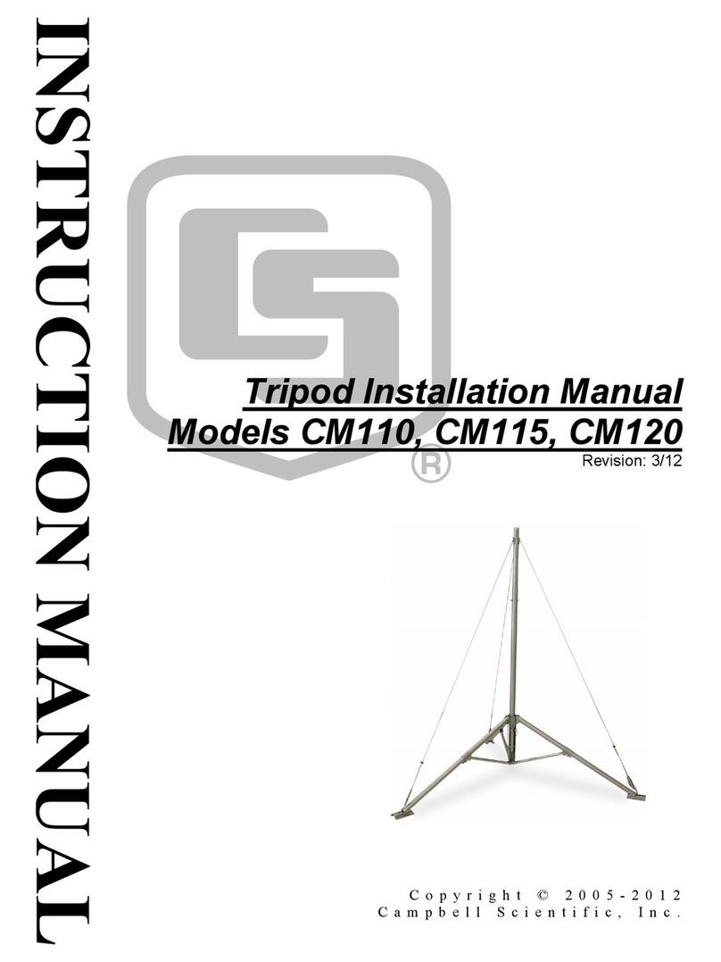
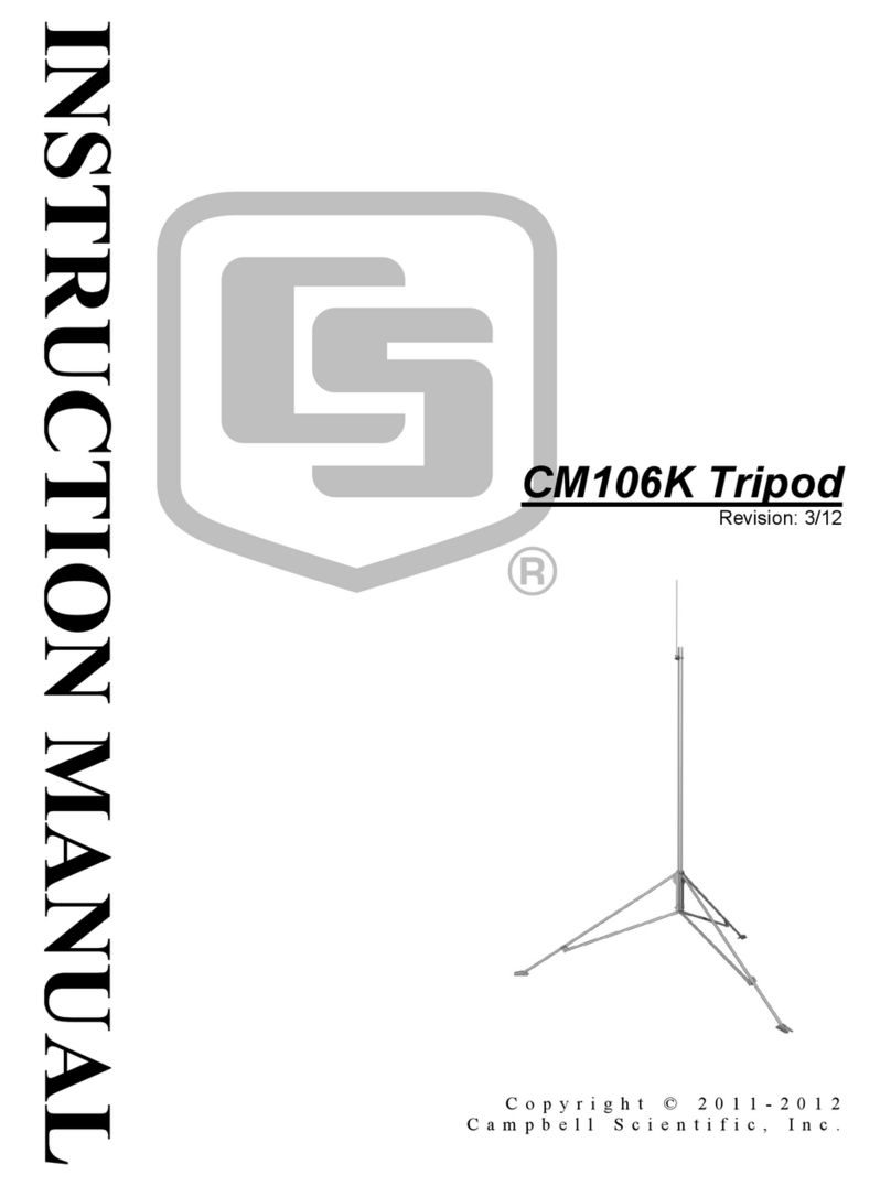
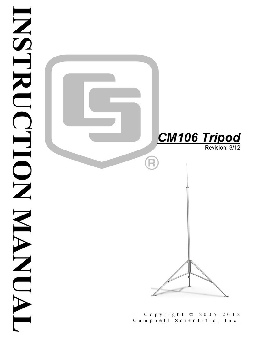
Table of Contents
PDF viewers: These page numbers refer to the printed version of this document. Use the
PDF reader bookmarks tab for links to specific sections.
1. Introduction ................................................................. 1
2. Cautionary Statements ............................................... 1
3. Initial Inspection ......................................................... 2
3.1 Inspect Packaging ................................................................................ 2
3.2 Tripod Components.............................................................................. 2
3.3 Tools List (for tripod, mast, enclosures, and crossarms) ...................... 4
4. Overview ...................................................................... 4
5. Specifications ............................................................. 5
6. Installation ................................................................... 6
6.1 Tripod Installation ................................................................................ 6
6.1.1 Tripod Base ................................................................................... 6
6.1.1.1 Mounting on a Relatively Flat Area ................................... 7
6.1.1.2 Mounting on an Incline ...................................................... 7
6.1.2 Mast .............................................................................................. 8
6.1.3 Installing the Optional Guy Kit ................................................... 10
6.1.4 Staking the Tripod Feet ............................................................... 12
6.1.5 Tripod Grounding ....................................................................... 13
6.1.6 Crossarm Attachment.................................................................. 15
6.1.7 Enclosure Attachment ................................................................. 15
6.1.7.1 Enclosure Mounting to Tripod Mast ................................ 15
6.1.7.2 Enclosure Mounting to Tripod Leg .................................. 16
6.2 Mounting Brackets ............................................................................. 18
6.2.1 CM210 Crossarm Mounting Kit ................................................. 18
6.2.2 CM216 Mast Mounting Kit ........................................................ 19
6.2.3 CM220 Right Angle Mounting Kit ............................................. 20
6.2.4 CM225 and 18098 Pyranometer Mounting Stand....................... 21
6.2.5 CM230 Adjustable Angle Mounting Kit..................................... 22
6.2.6 CM235 Magnetic Mounting Stand ............................................. 23
6.2.7 R.M. Young Gill Radiation Shields ............................................ 24
Appendix
A. CM106B Allowable Wind Speeds .......................... A-1
i

Table of Contents
Figures
1-1. Typical tripod-based weather station ................................................... 1
3-1. Tripod components .............................................................................. 3
4-1. CM106B tripod with lightning rod and guy wires............................... 4
6-1. Tripod leg, leg clamp components ...................................................... 6
6-2. Comparison of one leg pointing downhill (right) versus two legs
pointing downhill ............................................................................. 7
6-3. Tripod mast and insert ......................................................................... 8
6-4. Mast attachment to tripod base ............................................................ 9
6-5. Guy collar .......................................................................................... 10
6-6. Leg attachment .................................................................................. 11
6-7. Staking the tripod feet ....................................................................... 12
6-8. Ground rod and clamp ....................................................................... 13
6-9. Lightning rod ..................................................................................... 14
6-10. CM204 Crossarm .............................................................................. 15
6-11. Enclosure with the –MM bracket ...................................................... 16
6-12. Enclosure with the –LM bracket ....................................................... 17
6-13. CM210 Crossarm Mounting Kit (shown with user-supplied pipe) ... 18
6-14. CM216 Mast Mounting Kit ............................................................... 19
6-15. CM220 Right Angle Mounting Kit ................................................... 20
6-16. CM225 Pyranometer Mounting Stand ............................................... 21
6-17. CM230 Adjustable Angle Mounting Kit ........................................... 22
6-18. CM235 Magnetic Mounting Stand .................................................... 23
6-19. R.M. Young Gill Radiation Shield .................................................... 24
ii

CM106B Tripod
1. Introduction
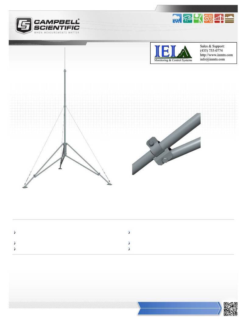
The CM106B is a general purpose tripod that can be used for mounting
sensors, solar panels, antennas, and instrument enclosures. FIGURE 1-1 shows
the CM106B being used in a typical weather station configuration.
FIGURE 1-1. Typical tripod-based weather station
2. Cautionary Statements
x READ AND UNDERSTAND the Precautions section at the front of this
manual.
x WARNING — Ensure structural integrity during setup and weather
extremes to minimize the chance of damaging the tripod or instruments.
Read all instructions carefully. Once the tripod is in full vertical position,
securely fasten it to the ground using ground spikes.
1

CM106B Tripod
x WARNING — For installations where soil structure is questionable or the
tripod may experience high wind loads, concrete footings for the tripod
feet and guy anchors should be considered.
3. Initial Inspection
3.1 Inspect Packaging
Upon receiving the CM106B, inspect the packaging and contents for damage.
Claims for shipping damage must be filed with the shipping company.
Locate the packing slip for the order and compare the items listed on the
packing slip to the items that were actually shipped. Report any discrepancies
to Campbell Scientific.
3.2 Tripod Components
FIGURE 3-1 shows the tripod components. The tripod base is packaged with
the mast, mast extension, ground rod, lightning rod, and (6) stakes. The ground
rod clamp, lightning rod, lightning rod clamp, cable ties, and ground wires are
enclosed in a bag. The optional guy kit is packaged separately.
2

CM106B Tripod
FIGURE 3-1. Tripod components
(12) Cable Ties (6) Stakes
Ground Wires
Ground Ro
d
and Clamp
Base
Mast
Lightning Ro
d
and Clamp
Mast Extension
3

CM106B Tripod
3.3 Tools List (for tripod, mast, enclosures, and crossarms)
1/2-in. and 7/16-in. open end wrenches
adjustable wrench
Phillips head screw drivers (medium, small)
Straight bit screwdrivers (large, medium)
12-in. torpedo level
side-cut pliers
pencil
tape measure
compass and site declination angle
shovel
sledge hammer (for driving ground rod and stakes)
step ladder
4. Overview
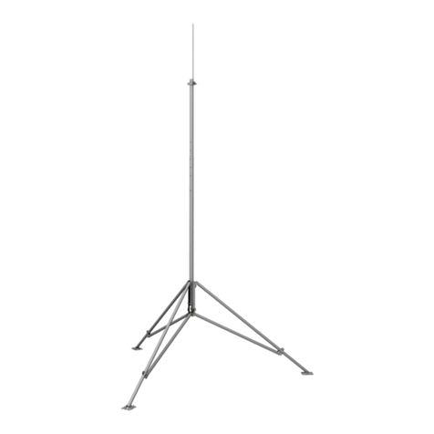
The CM106B (FIGURE 4-1) is constructed from galvanized steel, with
individually adjustable legs that allow installation over uneven terrain.
The CM106B includes lightning and ground rods, ground cables, UV resistant
cable ties, and stakes for securing the tripod feet to the ground. An optional
guy kit is recommended for sites that experience high wind speeds (see Section
5, Specifications). Instrument enclosures can be purchased with mounting
brackets that attach to either the mast or leg section as shown in Section 6.1.7,
Enclosure Attachment.
The CM106B can be used for a variety of applications. For meteorological
stations, sensors are mounted to the tripod using mounting brackets appropriate
for the model of sensor. For non-meteorological applications, the tripod can be
used to mount instrument enclosures, solar panels, junction boxes, or antennas.
FIGURE 4-1. CM106B tripod with lightning rod and guy wires
4

CM106B Tripod
5. Specifications
Mast Height
Upper Mast Retracted: 2.1 m (7 ft) to 2.8 m (9.3 ft)
Upper Mast Extended: 3 m (10 ft) to 3.7 m (12.3 ft)
Vertical Load Limit: 200 kg (440 lb)
Mast Outer Diameter
Main Lower Mast: 48 mm (1.90 in)
Retractable Upper: 44 mm (1.74 in)
Base Diameter: 2.7 m (8.7 ft) to 3.5 m (11.5 ft)
Leveling Adjustment: Slide collars on each leg, adjust individually
Leg Base: 4.5 in. by 5.5 in. with four 0.62 in. holes for
stakes
Portability: Collapsible to 8 in. diameter by 6 ft length
Weight with Mast: 24.5 kg (54 lb)
Maximum Slope Angle: 45° or 100% grade
Allowable Wind Speeds*
Tripod Configuration Sustained Wind Wind Gust
Mast Extended, Unguyed 62 mph (28 m s–1) 81 mph (36 m s–1)
Mast Retracted, Unguyed 80 mph (36 m s–1) 104 mph (46 m s–1)
Mast Extended, Guyed 102 mph (45 m s–1) 132 mph (59 m s–1)
Mast Retracted, Guyed 122 mph (55 m s–1) 159 mph (71 m s–1)
*Allowable wind speed values assume:
x Sensors (effective area = 1.4 ft2) at top of mast
x Solar panel (10.5 in x 16.5 in) at mast base
x Enclosure (14 in x 16 in) mounted to leg
x Guy wires attached to mast at 3.8 ft above tripod body
x Adequate ground anchors (stakes alone may not resist foot vertical
pullout force)
x See Appendix A for more information on maximum allowable wind
speeds.
5

CM106B Tripod
6. Installation
6.1 Tripod Installation
6.1.1 Tripod Base
The tripod base has three independently adjustable legs allowing the tripod to
be installed over non-level terrain.
Prepare the area where the tripod will be installed. The tripod requires an area
approximately 2.7 to 3.5 m (8.7 to 11.5 ft) in diameter. Natural vegetation and
the ground surface should be disturbed as little as possible, but brush and tall
weeds should be removed.
Stand the tripod base up on end, and rotate the feet perpendicular to the legs.
Each leg has a leg clamp and clamping bolt as shown in FIGURE 6-1.
FIGURE 6-1. Tripod leg, leg clamp components
Leg Clamp
Clamping Bolt
6

CM106B Tripod
6.1.1.1 Mounting on a Relatively Flat Area
Loosen the tension bolt and extend each leg. With the legs extended, orient the
tripod so that one of the legs points South (assuming the instrument enclosure
with –MM Mast Mount bracket will face North). If the instrument enclosure
has the –LM Leg Mount bracket, orient the tripod so the enclosure will mount
to one of the three leg mount positions on the tripod, facing the desired
direction. The tripod is typically plumbed after the mast has been installed, as
described in Section 6.1.2, Mast.
6.1.1.2 Mounting on an Incline
Loosen the tension bolt and extend each leg. With the legs extended, orient the
tripod so that one leg points downhill and the other two legs point uphill. The
tripod is more stable with only one leg pointed downhill because the mast is
closer to the center of the footprint (see FIGURE 6-2).
The tripod is typically plumbed after the mast has been installed, as described
in Section 6.1.2, Mast.
FIGURE 6-2. Comparison of one leg pointing downhill (right) versus
two legs pointing downhill
7

CM106B Tripod
6.1.2 Mast
The CM106B includes a mast extension that can be fully extended for a 3 m
(10 ft) height, or partially extended for a 2.1 m (7 ft) height. Remove the bolts
in the extension, align the holes in the insert with holes in the mast, and install
the four bolts previously removed. Two additional holes make it possible for
the extension to extend 8 in. or 12 in., or 20 in., 24 in., or 28 in. above the mast
depending on which end is inserted in the mast.
FIGURE 6-3. Tripod mast and insert
Mast extension
fully extended
Mast
Mast extension
retracted
8

CM106B Tripod
FIGURE 6-4. Mast attachment to tripod base
Loosen the six bolts on the tripod base. FIGURE 6-4 shows the location of
four of these bolts. The remaining bolts are in the same position on the third
tripod leg. Slide the mast into the tripod base, making sure that it extends
below the lower bolts and rests on the tabs. Tighten the six bolts to secure the
mast.
Plumb the tripod by adjusting the northeast and south facing legs. With a level
on the East side of the mast, adjust the Northeast leg for plumb. With the level
on the South side of the mast, adjust the South leg for plumb. Tighten the
tension bolts after the adjustments have been made.
Mas
t
Tab
Bolts
Preset at Factory
Preset at Factory
9

CM106B Tripod
6.1.3 Installing the Optional Guy Kit
Part 29813, CM106B Guy Kit, can be ordered separately for areas that
experience high wind speeds (Section 5, Specifications). Install the guy
brackets to the mast as shown in FIGURE 6-5. Attach the three guy wires to
the guy collar and slide the collar over the mast so that the collar butts against
the brackets.
FIGURE 6-5. Guy collar
On the end of each guy line is a case and hardware to attach to the turnbuckles.
Unscrew the turnbuckles so that only 1/2 in. of thread extends beyond the
inside of the turnbuckle body. Attach the case and turnbuckle to the tripod leg
as shown in FIGURE 6-6. Loosen the two clamp nuts, and remove the slack in
the guy line by feeding the load end of the guy wire through the case while
pulling up on the free end.
After the slack has been removed from the guy lines, tighten the clamp nuts,
and then tighten the turnbuckles to the desired tension.
Guy Collar
Guy Wire
Guy Bracket
10

CM106B Tripod
FIGURE 6-6. Leg attachment
Clamp Nut
11

CM106B Tripod
6.1.4 Staking the Tripod Feet
Six stakes are provided for securing the tripod feet to the ground. Drive two
stakes through holes in each foot at an angle as shown in FIGURE 6-7.
Stakes may not be adequate depending on soil structure, maximum wind
speeds experienced at the site, mast height, or wind load from the
instrumentation. For questionable situations, additional stakes (pn 17049) or
even concrete footings for the tripod feet and guy anchors should be
considered.
FIGURE 6-7. Staking the tripod feet
12
Other manuals for CM106B
2
Table of contents
Other Campbell Camera Accessories manuals

Campbell
Campbell CM110 User manual

Campbell
Campbell CM110 User manual

Campbell
Campbell CM106 User manual

Campbell
Campbell CM106B User manual

Campbell
Campbell CM110 User manual

Campbell
Campbell CM106BK User manual

Campbell
Campbell CM110 User manual

Campbell
Campbell CM110 User manual

Campbell
Campbell CM106 User manual

Campbell
Campbell CM106K User manual