Campbell CM110 User manual

Tripod Installation Manual
Models CM110, CM115, CM120
Revision: 3/12
Copyright © 2005-2012
Campbell Scientific, Inc.


Warranty
“PRODUCTS MANUFACTURED BY CAMPBELL SCIENTIFIC, INC. are
warranted by Campbell Scientific, Inc. (“Campbell”) to be free from defects in
materials and workmanship under normal use and service for twelve (12)
months from date of shipment unless otherwise specified in the corresponding
Campbell pricelist or product manual. Products not manufactured, but that are
re-sold by Campbell, are warranted only to the limits extended by the original
manufacturer. Batteries, fine-wire thermocouples, desiccant, and other
consumables have no warranty. Campbell's obligation under this warranty is
limited to repairing or replacing (at Campbell's option) defective products,
which shall be the sole and exclusive remedy under this warranty. The
customer shall assume all costs of removing, reinstalling, and shipping
defective products to Campbell. Campbell will return such products by surface
carrier prepaid within the continental United States of America. To all other
locations, Campbell will return such products best way CIP (Port of Entry)
INCOTERM® 2010, prepaid. This warranty shall not apply to any products
which have been subjected to modification, misuse, neglect, improper service,
accidents of nature, or shipping damage. This warranty is in lieu of all other
warranties, expressed or implied. The warranty for installation services
performed by Campbell such as programming to customer specifications,
electrical connections to products manufactured by Campbell, and product
specific training, is part of Campbell’s product warranty. CAMPBELL
EXPRESSLY DISCLAIMS AND EXCLUDES ANY IMPLIED
WARRANTIES OF MERCHANTABILITY OR FITNESS FOR A
PARTICULAR PURPOSE. Campbell is not liable for any special, indirect,
incidental, and/or consequential damages.”

Assistance
Products may not be returned without prior authorization. The following
contact information is for US and international customers residing in countries
served by Campbell Scientific, Inc. directly. Affiliate companies handle
repairs for customers within their territories. Please visit
www.campbellsci.com to determine which Campbell Scientific company serves
your country.
To obtain a Returned Materials Authorization (RMA), contact CAMPBELL
SCIENTIFIC, INC., phone (435) 227-9000. After an applications engineer
determines the nature of the problem, an RMA number will be issued. Please
write this number clearly on the outside of the shipping container. Campbell
Scientific's shipping address is:
CAMPBELL SCIENTIFIC, INC.
RMA#_____
815 West 1800 North
Logan, Utah 84321-1784
For all returns, the customer must fill out a "Statement of Product Cleanliness
and Decontamination" form and comply with the requirements specified in it.
The form is available from our web site at www.campbellsci.com/repair. A
completed form must be either emailed to repair@campbellsci.com or faxed to
(435) 227-9106. Campbell Scientific is unable to process any returns until we
receive this form. If the form is not received within three days of product
receipt or is incomplete, the product will be returned to the customer at the
customer's expense. Campbell Scientific reserves the right to refuse service on
products that were exposed to contaminants that may cause health or safety
concerns for our employees.

Tripod Installation Table of Contents
PDF viewers: These page numbers refer to the printed version of this document. Use the
PDF reader bookmarks tab for links to specific sections.
1. General .........................................................................1
2. Specifications ..............................................................2
3. Tools List (for tripod, mast and crossarm) ...............3
4. Tripod Components.....................................................3
5. Tripod Installation........................................................4
5.1 Tripod Base...............................................................................................4
5.2 Mast ..........................................................................................................5
5.3 Installing the Guy Kit ...............................................................................9
5.3.1 Guy Duckbill Anchor Kits ............................................................11
5.3.2 Lowering Mast after Attaching Guy Wires...................................13
5.4 Staking the Tripod Feet ..........................................................................14
5.5 Tripod Grounding ...................................................................................15
5.6 Crossarm Attachment .............................................................................17
5.7 Enclosure Attachment.............................................................................17
5.7.1 Enclosure Mounting to Tripod Mast.............................................17
5.7.2 Enclosure Mounting to Tripod Leg...............................................18
6. Mounting Brackets ....................................................20
6.1 CM210 Crossarm Mounting Kit.............................................................20
6.2 CM216 Mast Mounting Kit ....................................................................21
6.3 CM220 Right Angle Mounting Kit.........................................................22
6.4 CM225 Pyranometer Mounting Stand....................................................23
6.5 CM230 Adjustable Angle Mounting Kit ................................................24
6.6 CM235 Magnetic Mounting Stand .........................................................25
6.7 RM Young Gill Radiation Shields..........................................................26
Appendix
A. Tripod Tote Bag....................................................... A-1
Figures
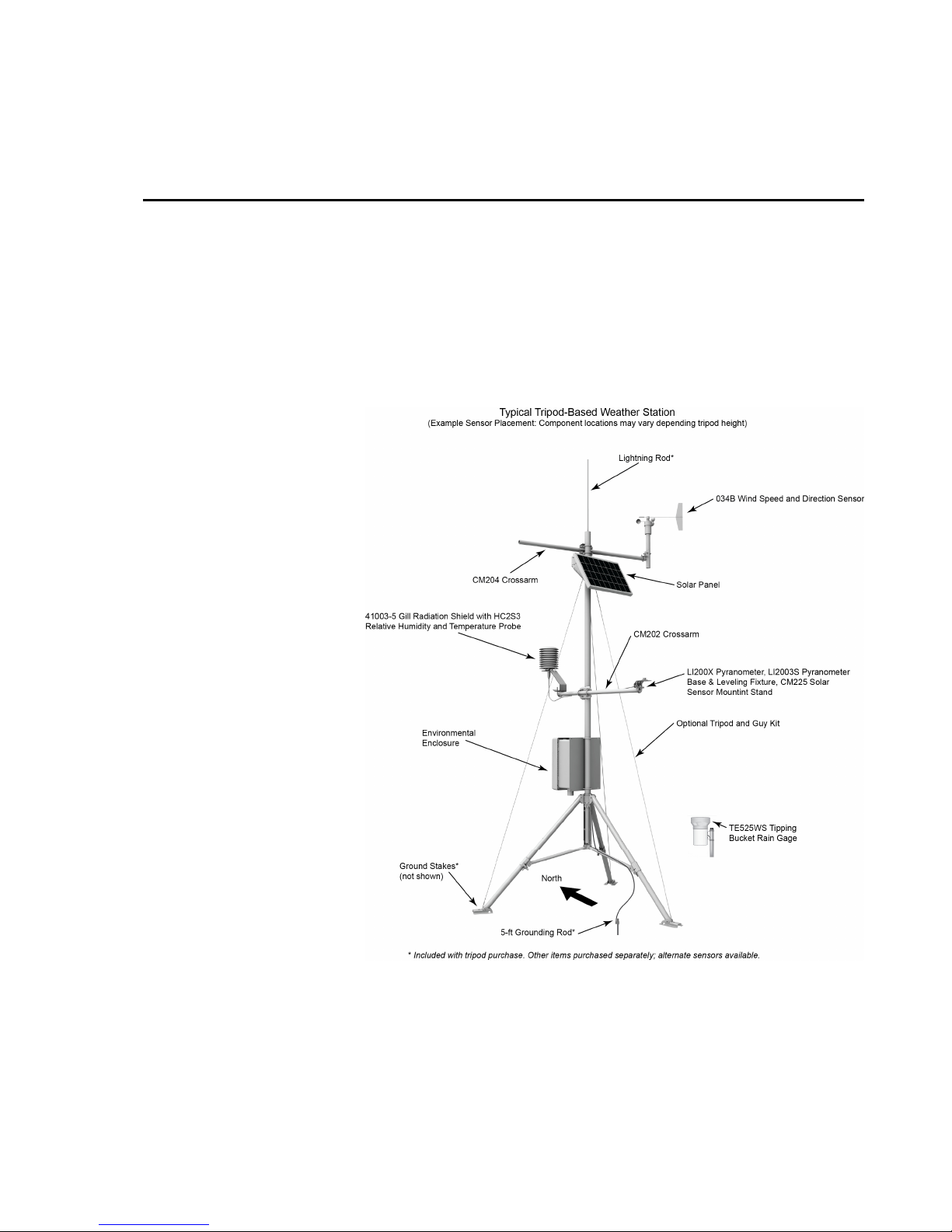
1-1. Typical tripod-based weather station.......................................................1
2-1. 60-degree guy angle ................................................................................3
4-1. Tripod components..................................................................................4
5-1. Tripod leg, slide collar components ........................................................5
i

Tripod Installation Table of Contents
ii
5-2. Tripod mast and insert ............................................................................ 6
5-3. Mast attachment to tripod base ............................................................... 7
5-4. Mast lock bracket.................................................................................... 8
5-5. Guy collar ............................................................................................... 9
5-6. Guy cinch and lever arm....................................................................... 10
5-7. Mechanical drawing of guy hook and case........................................... 11
5-8. Duckbill guy anchor ............................................................................. 12
5-9. Top view and guy anchor layout .......................................................... 13
5-10. Staking the tripod feet......................................................................... 14
5-11. Ground rod and clamp ........................................................................ 15
5-12. Lightning rod and tripod grounding lug ............................................. 16
5-13. CM204 Crossarm................................................................................ 17
5-14. Enclosure with the –MM Bracket....................................................... 18
5-15. Enclosure with the –LM Bracket........................................................ 19
6-1. CM210 Crossarm Mounting Kit........................................................... 20
6-2. CM216 Mast Mounting Kit .................................................................. 21
6-3. CM220 Right Angle Mounting Kit....................................................... 22
6-4. CM225 Pyranometer Mounting Stand.................................................. 23
6-5. CM230 Adjustable Angle Mounting Kit .............................................. 24
6-6. CM235 Magnetic Mounting Stand ....................................................... 25
6-7. RM Young Gill Radiation Shield ......................................................... 26

Tripod Installation Manual
Models CM110, CM115, CM120
1. General
The CM110 (10 feet), CM115 (15 feet), and CM120 (20 feet) tripods are
corrosion-resistant stainless steel instrument mounts that support the
attachment of sensors, solar panels, and environmental enclosures. A guy kit is
included with the CM115 and CM120 models, and is an option for the CM110.
A durable Tripod Tote Bag is available as an option.
FIGURE 1-1. Typical tripod-based weather station
1

Tripod Installation Manual Models CM110, CM115, CM120
2. Specifications
CM115 (see note 3) CM120 (see note 3)CM110
Height w/mast insert: 10’ (3 m) 15.5’ (4.7 m) 21.0’ (6.4 m)
Weight: 34 lbs (15 kg) 40 lbs (18 kg) 46 lbs (21 kg)
Base diameter w/legs extended: 7 ft (2 m) 7 ft (2 m) 7 ft (2 m)
Dimensions of collapsed tripod: 6” x 6” x 57”
(15 x 15 x 145 cm)
6” x 6” x 57”
(15 x 15 x 145 cm)
6” x 6: x 57”
(15 x 15 x 145 cm)
Vertical load limit: 100 lb (45 kg) 100 lb (45 kg) 100 lb (45 kg)
Mast description
Number of sections: 1 2 3
Length: 4.6’ (1.4m) 9.3’ (2.8 m) 14.0’ (4.3 m)
Length w/insert: 8.6’ (2.6 m) 13.3’ (4.1 m) 18.0’ (5.5 m)
OD: 1.9” (4.8 cm) 1.9” (4.8 cm) 1.9” (4.8 cm)
Insert OD: 1.75” (4.45 cm) 1.75” (4.45 cm) 1.75” (4.45 cm)
Mounting hole in tripod foot: 0.75” diameter hole
for user-supplied
0.5” J-bolts
0.75” diameter hole
for user-supplied
0.5” J-bolts
0.75” diameter hole
for user-supplied
0.5” J-bolts
Wind load recommendations
Sustained wind (mph): *75 (unguyed)
80 (guyed at feet)
*56.25 (guyed at feet)
75 (guyed at 60°)
*42.25 (guyed at feet)
65 (guyed at 60°)
Gust tolerance (mph): 95 (unguyed)
100 (guyed at feet)
71.25 (guyed at feet)
95 (guyed at 60°)
55.25 (guyed at feet)
85 (guyed at 60°)
Tote bag dimensions: 8” (20 cm) diameter,
60” (152 cm) length
8” (20 cm) diameter,
60” (152 cm) length
8” (20 cm) diameter,
60” (152 cm) length
2

Tripod Installation Manual Models CM110, CM115, CM120
60º
60º
*Anchors must hold at least
400 lbf in both x, y axis
FIGURE 2-1. 60-degree guy angle
3. Tools List (for tripod, mast and crossarm)
1/2” and 7/16” open end wrenches
adjustable wrench
socket wrench with 1/2”and 7/16” deep sockets (optional)
Phillips head screw driver (medium)
Straight bit screwdriver (large)
12” torpedo level
side-cut pliers
pencil
tape measure
compass and site declination angle
shovel
sledge hammer (for driving ground rod and stakes)
step ladder
4. Tripod Components
Figure 4-1 shows the tripod components packaged for shipment. The tripod
base is packaged with the mast, ground rod, lightning rod and (6) stakes. The
ground rod clamp, lightning rod, and grounding wires are enclosed in a bag.
The guy kit (optional for the CM110), and tripod tote bag (optional) are
packaged separately. The CM115 and CM120 tripods include additional mast
sections. A diagram showing how to stow the components inside the tote bag
is shown in Appendix A.
3

Tripod Installation Manual Models CM110, CM115, CM120
FIGURE 4-1. Tripod components
5. Tripod Installation
5.1 Tripod Base
Tripod installation near power lines is dangerous. The
minimum safe recommended distance from overhead
power lines is 2 times the height of the tripod and mast
combined. Call Blue Stakes to locate buried utilities
prior to installation.
WARNING
All three models of tripods use the same tripod base. Each leg is adjustable,
which allows the tripod to be adjusted for non-level terrain.
Prepare the area where the tripod will be installed. The tripod requires an area
approximately 7 feet in diameter. Natural vegetation and the ground surface
should be disturbed as little as possible, but brush and tall weeds should be
removed.
Stand the tripod base up on end, and rotate the feet perpendicular to the legs.
Each leg has a slide collar and T-knob with a spring loaded pin that locks into
holes located on the underside of the leg as shown in Figure 5-1.
Extend each leg until the pin engages in a hole (depress the tab to disengage
the pin from a hole). With the legs extended, orient the tripod so that the open
channel of the tripod base faces North. The tripod is typically plumbed after
the mast has been installed, as described in Section 5.2.
4

Tripod Installation Manual Models CM110, CM115, CM120
Holes for Pins
Slide Collar
Spring-Loaded Pin
T-Knob
FIGURE 5-1. Tripod leg, slide collar components
5.2 Mast
The CM110, CM115 and CM120 tripods have one, two or three mast sections
respectively. The top mast section has a 48” long insert with a series of holes
that can be extended to lengthen the mast. Remove the bolt that secures the
insert to the inside of the mast, and slide the insert out from the mast to see the
different hole locations. Slide the insert back into the mast, aligning the
appropriate holes of the insert with holes in the mast, and replace the bolt.
Additional 56” mast section(s) included with the CM115 and CM120 tripods
have a 16” long insert that is used to connect the mast sections together.
Remove the bolt that secures the insert to the inside of the mast and extend the
insert 8”. Align the holes and replace the bolt. Attach additional mast sections
by sliding the bottom of the next mast section over the insert of a lower section,
aligning the holes and installing the bolt. Typically the bottom mast section is
attached to the tripod and tilted down to a horizontal position, and the
additional mast sections bolted to the bottom section.
5

Tripod Installation Manual Models CM110, CM115, CM120
Insert
Mast
FIGURE 5-2. Tripod mast and insert
The tripod base has two sets of right-angled holes for attaching the mast;
typically the lower set is used (Figure 5-3A). The mast is attached to the base
with a pin, and secured in the upright position with a locking bracket. Both the
pin and the locking bracket are secured with a lanyard.
To attach the lower mast section, hold the mast upright and align the hole in the
bottom of the mast with the holes in the tripod base. Insert the pin through the
holes, and rotate the wire retainer over the end of the pin as shown in Figure
5-3B. The pin should be seated in the bottom of the hole when the mast is
upright. Lift the mast up so that the pin is in the upper end of the hole to allow
the mast to be tilted down to a horizontal position.
6

Tripod Installation Manual Models CM110, CM115, CM120
FIGURE 5-3. Mast attachment to tripod base
Secure the mast in the upright position by installing the locking bracket (Figure
5-4A). Insert the top of the bracket into the notches in the tripod base, and
using both thumbs, press the bracket into the body of the base until the lower
tabs lock into position. Install the pin as shown in Figure 5-4C. To remove the
bracket, remove the pin and squeeze the lower part of the bracket to disengage
the tabs, then rotate the bracket out and up.
Plumb the tripod by adjusting the northeast and south facing legs. With a level
on the East side of the mast, adjust the Northeast leg for plumb. With the level
on the South side of the mast, adjust the South leg for plumb.
Pin
Right-Angled Hole
Wire
Retainer
7

Tripod Installation Manual Models CM110, CM115, CM120
Locking Bracket
Lower Tabs
Pin
FIGURE 5-4. Mast lock bracket
8

Tripod Installation Manual Models CM110, CM115, CM120
5.3 Installing the Guy Kit
The CM115 and CM120 tripods include a guy kit; the guy kit is an option for
the CM110. With the mast tilted down in the horizontal position, install the
guy collar over the mast insert, and attach the guy wires as shown in Figure
5-5. Return the mast to the upright position and install the locking bracket.
Guy Collar
Guy Wire
FIGURE 5-5. Guy collar
On the end of each guy line is a case consisting of a hook, clamp, and lever
arm. Rotate the lever arm to the “open” position, and attach the hook to the
tripod leg as shown in Figure 5-6. Loosen the Phillips screw, and remove the
slack in the guy line by feeding the load end of the guy wire through the wedge
while pulling up on the dead end (Figure 5-7).
After the slack has been removed from the guy lines, tighten the Phillips
screws and rotate the lever arms to “closed” position to tension the guy lines.
9

Tripod Installation Manual Models CM110, CM115, CM120
Phillips Screw
Lever Arm “Open”
Hook
Lever Arm “Closed”
FIGURE 5-6. Guy cinch and lever arm
10

Tripod Installation Manual Models CM110, CM115, CM120
dead end
load end
hook
Phillips screw
lever
FIGURE 5-7. Mechanical drawing of guy hook and case
5.3.1 Guy Duckbill Anchor Kits
Duckbill anchors are recommended for areas subjected to higher winds. They
allow the guy wires to be anchored at points beyond the feet, thereby
increasing the rating of the tripod for higher winds.
Two duckbill anchor kits are offered for these lightweight tripods. The 19282
Guy Duckbill Standard Anchor Kit is for standard soils, and the 25699 Guy
Duckbill Heavy Duty Kit is for aggressive soils. Aggressive soils have:
•Resistivity of less than 3000 ohm-cm
•pH of less than 5
•Chloride of greater than 1000 ppm
•Sulfate of greater than 500 ppm
•Poor aeration
The 19282 and 25699 have their own drive bar. The 19282 also has three
duckbill anchors with a cable attached to each of them. At the end of the cable
is a loop for connecting the guy wires. The 25699 has a threaded rod attached
to each of the three duckbill anchors instead of the cable. At the end of the
threaded rod is a metal ring for connecting the guy wires.
The duckbill anchors are driven to the ground at a 60-degree guy angle as
shown in Figure 5-8. Locate the anchors on a 7.5’ radius for the CM115, or a
10’ radius for the CM120 as shown in Figure 5-9. Specifications for sustained
wind speed and gust tolerance are given based on guy angle, and the ability of
the anchors to hold at least 400 lbf.
Dukbill anchors are not suitable for rocky or sandy soils; the
UTEYE anchors should be considered for these types of soils.
NOTE
11

Tripod Installation Manual Models CM110, CM115, CM120
It is important that the anchors be driven at the same angle as the guy wires.
Insert the drive bar into the anchor body and drive the anchor into the ground
using a sledgehammer until only the top half of the loop or metal ring remains
above the ground. Place a bar or highlift jack through the loop or metal ring
and jack the anchor up about four inches to rotate the anchor into the load-lock
position.
Failure to install and lock the anchor at the correct
angle will result in the anchor cable cutting through
the soil until the angles equalize, causing slack
WARNING
60o
Drive Ba
r
Duckbill Ancho
r
FIGURE 5-8. Duckbill guy anchor
12

Tripod Installation Manual Models CM110, CM115, CM120
120
Distance between anchors
RADIUS
TILT DIRECTION
(NORTH)
CENTER POINT
ANCHOR LOCATIONS
(3) PLCS
Radius Distance Between Anchors
CM115 7.5’ 13’
CM120 10’ 17.3’
FIGURE 5-9. Top view and guy anchor layout
5.3.2 Lowering Mast after Attaching Guy Wires
Once the guy lines have been adjusted the lever arms can be “opened” and the
guy hooks removed to allow the mast to be lowered to the horizontal position.
13

Tripod Installation Manual Models CM110, CM115, CM120
5.4 Staking the Tripod Feet
Six stakes are provided for securing the tripod feet to the ground. Drive two
stakes through holes in each foot at an angle as shown in Figure 5-10.
Stakes may not be adequate depending on soil structure, maximum wind
speeds experienced at the site, mast height, or wind load from the
instrumentation. For questionable situations, additional stakes (PN 17049) or
even concrete footings for the tripod feet and guy anchors should be
considered.
FIGURE 5-10. Staking the tripod feet
14
Other manuals for CM110
4
This manual suits for next models
2
Table of contents
Other Campbell Camera Accessories manuals

Campbell
Campbell CM106K User manual

Campbell
Campbell CM106B User manual

Campbell
Campbell CM106 User manual

Campbell
Campbell CM10K User manual

Campbell
Campbell CM106B User manual

Campbell
Campbell CM106BK User manual

Campbell
Campbell CM110 User manual

Campbell
Campbell CM106B User manual

Campbell
Campbell CM106BE User manual

Campbell
Campbell CM110 User manual