Camtraptions PIR V3 User manual

!
!
Camtraptions+PIR+Motion+Sensor+v3#
Manual!
!
Firmware!Version!2.2!
!

Camtraptions PIR Motion Sensor v3 Manual Page 2
Index!
!
Index!......................................................................................................................!2!
What!is!a!PIR!Motion!Sensor?!.................................................................................!3!
What!is!new!in!Version!3?!.......................................................................................!3!
Primary!Controls!.....................................................................................................!4!
!"#$%&'''''''''''''''''''''''''''''''''''''''''''''''''''''''''''''''''''''''''''''''''''''''''''''''''''''''''''''''''''''''''''''''''''''''''''&(!
)*"+,-.%&'''''''''''''''''''''''''''''''''''''''''''''''''''''''''''''''''''''''''''''''''''''''''''''''''''''''''''''''''''''''''''''''''''''&(!
/01233&)*"+,-&'''''''''''''''''''''''''''''''''''''''''''''''''''''''''''''''''''''''''''''''''''''''''''''''''''''''''''''''''''''''''''''&4!
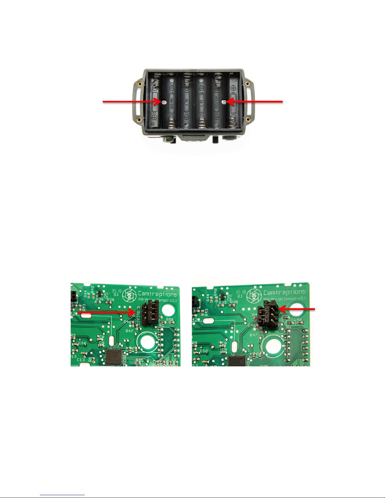
Operating!Modes!&!Channel!Selection!....................................................................!5!
).++"05&+-.&/6.7#+"05&829.&:&;-#00.$&''''''''''''''''''''''''''''''''''''''''''''''''''''''''''''''''''''''''''''''''''''&4!
/6.7#+"05&829.&''''''''''''''''''''''''''''''''''''''''''''''''''''''''''''''''''''''''''''''''''''''''''''''''''''''''''''''''''''''''&<!
="7.$.%%&;-#00.$&'''''''''''''''''''''''''''''''''''''''''''''''''''''''''''''''''''''''''''''''''''''''''''''''''''''''''''''''''''''''&<!
>.5#,?&829.&''''''''''''''''''''''''''''''''''''''''''''''''''''''''''''''''''''''''''''''''''''''''''''''''''''''''''''''''''''''''''''''&<!
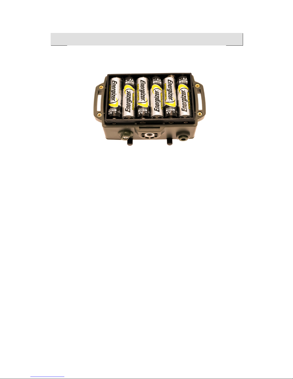
Inserting!Batteries!..................................................................................................!8!
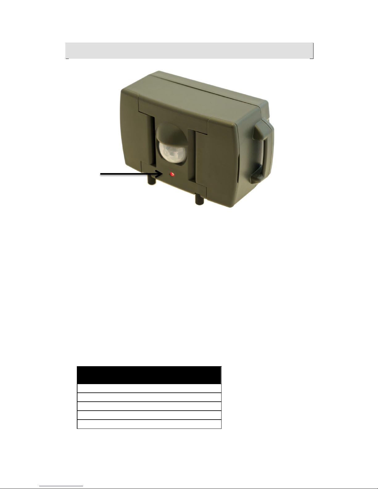
Red!LED!Indicator!...................................................................................................!9!
@2*.71A6&).BA.0,.&'''''''''''''''''''''''''''''''''''''''''''''''''''''''''''''''''''''''''''''''''''''''''''''''''''''''''''''''''''&C!
/6.7#+"05&829.&:&;-#00.$&D09",#+27&'''''''''''''''''''''''''''''''''''''''''''''''''''''''''''''''''''''''''''''''''''''&EF!
G$"50H.0+&:&).0%"+"I"+?&D09",#+27&''''''''''''''''''''''''''''''''''''''''''''''''''''''''''''''''''''''''''''''''''''''''''''&EF!
Mounting!the!Sensor!............................................................................................!11!
Long-term!Deployment!in!Wet!Conditions!............................................................!11!
Controlling!the!Field!of!View!.................................................................................!12!
Connecting!a!Wired!Camera!..................................................................................!13!
Connecting!a!Wireless!Camera!..............................................................................!13!
Sensitivity!Dial!......................................................................................................!14!
8"0"H"J"05&K#$%.&L7"55.7%&''''''''''''''''''''''''''''''''''''''''''''''''''''''''''''''''''''''''''''''''''''''''''''''''''''''''&E(!
Time!Dial!..............................................................................................................!15!
Luminosity!Threshold!Dial!.....................................................................................!16!
Program!Selection!................................................................................................!17!
Support!................................................................................................................!18!

Camtraptions PIR Motion Sensor v3 Manual Page 3
What!is!a!PIR!Motion!Sensor?!
All objects emit energy in the form of invisible infrared radiation. A passive
infrared (PIR) sensor detects movement of infrared-emitting sources within its
field of view. This allows it to sense when an animal passes in front. The term
“passive” refers to the fact that the sensor does not emit radiation but instead
monitors the levels if infrared radiation falling on it. As a result, PIR sensors
are very energy-efficient.
What!is!new!in!Version!3?!
The following new features have been add to this PIR:
1) Added an integrated wireless transmitter, compatible with Camtraptions
Wireless Receivers.
2) Redesigned sensitivity algorithm delivers faster response time with
more reliable false trigger filtering.
3) Now supporting three distinct operating modes: Still mode, Video mode
and Legacy mode
4) Support added for a wider range of cameras and flashes
!

Camtraptions PIR Motion Sensor v3 Manual Page 4
Primary!Controls!
The PIR is configured via three dials and a bank of six switches on the front.
There is also an On-off switch on the bottom of the device.
Dials!
The dials control the following functions:
Sensitivity – See Page 14
Time Variable – See Page 15
Luminosity Threshold or Secondary Time Variable – See Page 16
Note that the behaviour of the Time and Luminosity Dial varies based on the
program. The behaviour of the Sensitivity Dial is the same for all programs.
Switches!
The switches control the following functions:
1 & 2: Day / Night behaviour
Still mode
3: Dial function
4, 5, 6: Transmitter Program
Video mode:
3: Extend video length on additional motion off/on
4, 5 & 6: Video Program
!

Camtraptions PIR Motion Sensor v3 Manual Page 5
On-off!Switch!
The On-off switch is situated on the bottom of the device. Turn the switch to “|”
to turn the sensor on. Turn the switch to “O” to turn the sensor off.
On power-up, the LED on the front of the device will flash to indicate the
supply voltage and then there will be an 8 second delay while the sensor
calibrates. Thereafter, the LED will flash to indicate the Operating Mode and
Channel before commencing normal operation. See Page 9 for further details.
Operating!Modes!&!Channel!Selection!
The PIR v3 has three operating modes:
1. Stills mode: All programs focused on still shooting
2. Video mode: All programs focused on video shooting
3. Legacy mode: Replicates programs of PIR v2
The PIR v3 can be configured to work in one of seven different wireless
channels. These channels are compatible with Camtraptions Wireless
Triggers.
Setting!the!Operating!Mode!&!Channel!
It is intended that the operating mode and channel are set when the PIR is
set-up for the first time. Thereafter, it should not be necessary to adjust these
settings again unless it is necessary to swap between still and video mode. If
multiple PIRs are being used in a small area then set them to different
channels so they don’t interfere.
The operating mode and wireless channel of the transmitter are set via the
internal jumpers. To access the jumpers, open up the batter enclosure and

Camtraptions PIR Motion Sensor v3 Manual Page 6
remove the battery holder by unscrewing the two screws that secure it to the
enclosure.
The jumpers are located in the top right corner under the Camtraptions logo
and are labeled A, B, C and D. Place a connector so that it bridges the two
jumper pins to set the state to On. Place the connector so that it is mounted
on just one side, to set the jumper state to Off.
Important: when pulling up the jumper connectors, ensure the board is pushed
down so that it does not come away from the enclosure. If the board lifts from
the enclosure, the o-rings that seal the dials may pop off.
The power-up LED flash sequence provides a simple way to check the state
of the jumpers without removing the battery enclosure. See LED Indicator for
more.
The images below show example jumper placements:
Left: Jumpers A to D in the Off position with jumper connectors stowed on just the right pin.
Right: Jumper A in the On position (jumper connector spanning left and right pins) and
Jumpers B to D in the Off position (this time with jumper connectors stowed on the left pin).
!

Camtraptions PIR Motion Sensor v3 Manual Page 7
Operating!Mode!
The jumper marked A can be used to switch between stills and video mode.
Jumper A: Off: Stills mode (see Stills Manual)
On: Video mode (see Video Manual)
Wireless!Channel!
The jumpers marked B, C, D set the wireless channel. The jumper
configurations for each channel are shown below:
Setting
B
C
D
Channel 1
Off
Off
Off
Channel 2
On
Off
Off
Channel 3
Off
On
Off
Channel 4
Off
Off
On
Channel 5
On
On
Off
Channel 6
Off
On
On
Channel 7
On
On
On
Tx Disabled
On
Off
On
The corresponding channels on Camtraptions Wireless Receiver are as
follows:
Setting
1
2
3
4
Channel 1
On
Off
Off
Off
Channel 2
Off
On
Off
Off
Channel 3
Off
Off
On
Off
Channel 4
Off
Off
Off
On
Channel 5
On
On
Off
Off
Channel 6
Off
Off
On
On
Channel 7
On
On
On
On
Legacy!Mode!
This mode replicates the programs of the PIR v2. It is set as follows:
A: Off
B: On
C: Off
D: On
For instructions on how to use Legacy Mode, refer to the PIR v2 Manual.
!
!

Camtraptions PIR Motion Sensor v3 Manual Page 8
Inserting!Batteries!
Use a screwdriver to remove the four screws on the back of the device and
take off the back wall. Insert six AA batteries into the battery holder, taking
care to follow the polarity direction indicated on the holder. Check the sensor
turns on and then replace the back wall and the four screws. When replacing
the back wall, ensure that the seal around the edge is clean and free of
debris.
The sensor accepts either Alkaline or NiMH rechargeable batteries and will
operate while the supply voltage is greater than 3.7 volts. Please note that if
using a different type of battery or powering the sensor from an external
power source, the supply voltage should not exceed 9.6 volts.
When the sensor is first turned on, the red LED on the front indicates the
battery voltage, see Page 9.
!

Camtraptions PIR Motion Sensor v3 Manual Page 9
Red!LED!Indicator!
The red LED on the front of the PIR serves three functions:
1) Indicates the battery voltage on power-up
2) Indicates the Operating Mode and Channel setting
3) Helps sensor alignment and sensitivity testing during the first 5 minutes
Power-up!Sequence!
When the sensor is first turned on, the LED will flash up to 5 times. There is
then an 8 second delay before the sensor will flash four times and start
operating.
The number of flashes during the initial power-up phase provides a quick
indication of the remaining battery level. This battery indicator has been
calibrated to be most useful when the sensor is powered by six Alkaline
batteries.
The battery life thresholds are as follows:
Number of
flashes
Alkaline battery
life remaining
5
More than 80%
4
60%-80%
3
40%-60%
2
20%-40%
1
Less than 20%

Camtraptions PIR Motion Sensor v3 Manual Page 10
If you are using NiMH rechargeable batteries then the approximate thresholds
are as follows:
Number of
flashes
NiMH battery life
remaining
4
More than 90%
3
20%-90%
2
10%-20%
1
Less than 10%
Operating!Mode!&!Channel!Indicator!
Before the PIR starts operating it will flash four times. The length of each flash
corresponds to the Jumper settings inside the PIR. The first flash corresponds
to JPA, the second JPB and so on. A long flash indicates a jumper is On while
a short flash indicates it is off. Thus a long flash followed by three quick
flashes indicates the sensor is in Video mode, Channel 1. A short-long-short-
long sequence would correspond to legacy mode. See Page 7 for Operating
Mode and Channel jumper configuration.
Alignment!&!Sensitivity!Indicator!
After the power-up phase, the sensor will commence normal operation.
The LED will light up whenever motion is detected. This can be used as a
visual aid to help align the sensor so that it is only detecting motion in the
desired trigger zone. When you are using the LED to set-up your sensor, you
might want to leave your camera off to avoid taking unwanted images.
After 5 minutes the LED will be disabled in order to conserve battery power
and avoid drawing attention to the PIR sensor. If you want to reactive the LED
then you will need to turn the sensor off and then on again.
If the LED is illuminating in response to motion but the camera is not firing
then please check the following:
1) Some programs do not fire the camera (for example, several video
programs do not send full-press signals to the camera)
2) If using a wireless connection, the channel of your receiver might not
match the PIR transmitter
3) If in a “Night” program, then the camera will not fire if the ambient light
level is above the luminosity threshold set by the Luminosity Dial
4) If in a “Day” program, then the camera will not fire if the ambient light
level is below the luminosity threshold set by the Luminosity Dial
5) Some programs include long delays during which the camera will not
fire (for example, it is possible to set a delay of up to 60 seconds after
each burst)
6) Your camera may not be set-up correctly so double-check the settings
in the “Quick Start” guide in the Stills Manual

Camtraptions PIR Motion Sensor v3 Manual Page 11
Mounting!the!Sensor!
There is a standard tripod socket on the bottom of the sensor that allows it to
be mounted on a tripod or similar mounting accessory.
The device also has attachment points for a strap on either side so that it can
be strapped to a post or tree trunk.
The sensor is sealed so that the electronics and batteries are protected from
precipitation. However, it is possible for water to trickle inside via the camera
connecting cable socket if the sensor is not mounted with this socket facing
downwards. Therefore, it is important to mount the sensor the correct way up.
Long-term!Deployment!in!Wet!Conditions!
The Camtraptions PIR v3 is weather-sealed but it is still possible for moisture
to enter the device, particularly via the connecting cable socket. For long-term
deployment in wet and humid conditions, it can be a good idea to use
bathroom silicone sealant on this socket to improve the seal. Make sure the
bung or camera connecting cable are inserted into the socket and then apply
the sealant around the insert. Do not apply sealant if the bung or cable are not
inserted as it may get into the cable socket and make it unusable for wired
connections. As an additional precaution, you may also want to insert a small
sachet of silica gel desiccant inside the PIR (behind the batteries).
!

Camtraptions PIR Motion Sensor v3 Manual Page 12
Controlling!the!Field!of!View!
The detection zone is immediately in front of the white dome lens on the front
of the sensor.
The detection range is around 5m in front of the device but the precise
distance depends on the size of the subject, the sensitivity setting and the
relative temperature differential between the subject and the background.
The detection field of view is around 120 to 150 degrees horizontally. The
detector is most sensitive towards the centre of the detection zone.
It may be necessary to limit the detection area in order to have more control
over the position of the subject relative to the camera. To do this, open out the
flaps on either side of the sensor to limit the sensor’s field of view. Tighten the
knurled thumbscrews on the bottom of the device to secure the flaps in
position.

Camtraptions PIR Motion Sensor v3 Manual Page 13
Connecting!a!Wired!Camera!
Remove the bung in the socket on the bottom of the sensor and plug in the
camera connecting cable. Connect the other end of the cable to your
camera’s shutter release port.
Connecting!a!Wireless!Camera!
To connect your camera wirelessly:
•Ensure you know which channel the PIR transmitter is set to. By
default it is Channel 1.
•Set the Camtraptions wireless receiver to the corresponding channel.
•Connect the camera connecting cable to the “Camera” socket on the
receiver and the other end to the camera’s shutter release port.

Camtraptions PIR Motion Sensor v3 Manual Page 14
Sensitivity!Dial!
Turn the dial clockwise to increase sensitivity.
Turn the dial anticlockwise to decrease sensitivity.
Higher sensitivity results in faster response time and increased range. You will
also need to increase the sensitivity when photographing small creatures or in
hot conditions when the temperature differential between the subject and the
background is lower.
Minimizing!False!Triggers!
You can reduce the sensitivity by turning the dial anticlockwise if you are
getting an unacceptable level of false triggers.
However, before reducing the sensitivity, you should try to manage the scene
to avoid potential sources of unwanted motion. For example, position the
sensor so that it has a minimal amount of vegetation in the foreground that
could move in the wind.
In general, you should try to position the sensor so that the subject will be
much closer than anything that could cause false detections.

Camtraptions PIR Motion Sensor v3 Manual Page 15
Time!Dial!
Turn the dial clockwise to increase time duration.
Turn the dial anticlockwise to decrease time duration.
The Time Dial changes different durations depending on the program
selected. For example, it might be used to set the duration of a burst in Stills
mode or the video length in video mode. Refer to the relevant mode
documentation for further details.
!

Camtraptions PIR Motion Sensor v3 Manual Page 16
Luminosity!Threshold!Dial!
Turn the dial clockwise to increase the luminosity threshold.
Turn the dial anticlockwise to decrease the luminosity threshold.
The Camtraptions PIR sensor is able to vary its behaviour based on the
ambient light level. For example, the PIR can be configured to work only
during daylight, only during darkness or all of the time.
It is also possible to configure the PIR with no luminosity cut-off so that it will
work all of the time. In this situation, the Luminosity Threshold Dial is used to
set a Secondary Time Variable. Refer to the Program documentation below
for further details.
For Day and Night Programs, turn the dial to set the threshold between day
and night operation. For example, with the dial set somewhere in the middle,
and a Night Program selected, the camera will only be triggered in gloomy
and dark conditions. As the dial is turned anticlockwise the threshold is
lowered so the camera would only get triggered in darkness. If the dial were
turned fully clockwise, the camera would fire in all light conditions.
This behaviour is reversed in a Day Program; with the dial in the middle, the
camera would only fire in gloomy light and full daylight, with the dial turned
clockwise, it would only fire in bright sunlight and with the dial turned fully
anticlockwise, the camera would fire in all light conditions.
Please note that if you want the camera to fire in all conditions then it is
advisable to select a program without a luminosity cut-off to avoid the risk of
accidentally setting the luminosity threshold incorrectly and the camera not
operating for part of the day.

Camtraptions PIR Motion Sensor v3 Manual Page 17
Program!Selection!
Programs are set via switches 1 to 6 on the front of the device. These
switches are located under the watertight bung, behind the flap, to the left of
the sensor dome.
There are 64 unique switch combinations that can be used to select
programs. Refer to the Still or Video operating mode manuals for more
information.
!

Camtraptions PIR Motion Sensor v3 Manual Page 18
Support!
To share photographs and discuss camera trap techniques, please join our
group on Facebook: https://www.facebook.com/groups/camtraptions/
Other manuals for PIR V3
1
Table of contents