Camus Hydronics DynaFLO DOWB-S1 Series Manual

99-0400 Rev.00
DynaFLO Series
Installation and Service Manual
Indirect Domestic Hot Water Heater
Models DOWB-1 thru DOWB-8
WARNING
If the information in these instructions is not followed exactly, a fire or explosion may result causing property damage, personal injury
or death.
WHAT TO DO IF YOU SMELL GAS
Do not try to light any appliance,
Do not touch any electrical switch; do not use any phone in your building,
Immediately call your gas supplier from a neighbour’s phone. Follow the gas supplier’s instructions,
If you cannot reach your gas supplier, call the fire department.
A Qualified installer, service agency or the gas supplier must perform installation and service.
WARNING
Do not store or use gasoline or other flammable vapours and liquids in the vicinity of this or any other appliance.
TO THE INSTALLER: After installation, these instructions must be given to the end user or left on or near the appliance.
TO THE END USER: This booklet contains important information about this appliance. Retain for future reference.
H
HLW


99-0400 Rev.00
Contents
Part 1 - General Information.....................................................................................................................................................1
1.1 –Special Instructions to Owner ........................................................................................................................................................................1
1.2 –Product Overview.............................................................................................................................................................................................2
1.3 –Product Ratings................................................................................................................................................................................................2
1.3.1 –Capacity Ratings ...........................................................................................................................................................................................2
1.3.2 –Electrical Ratings ..........................................................................................................................................................................................2
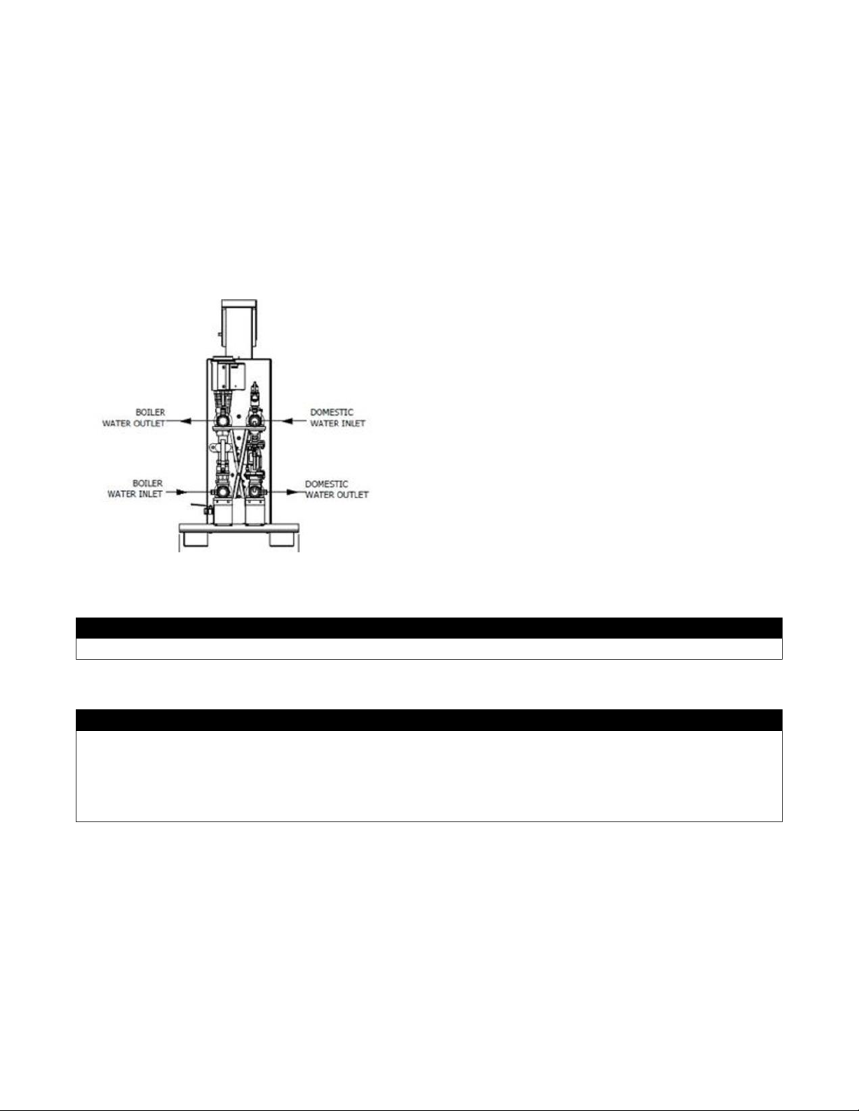
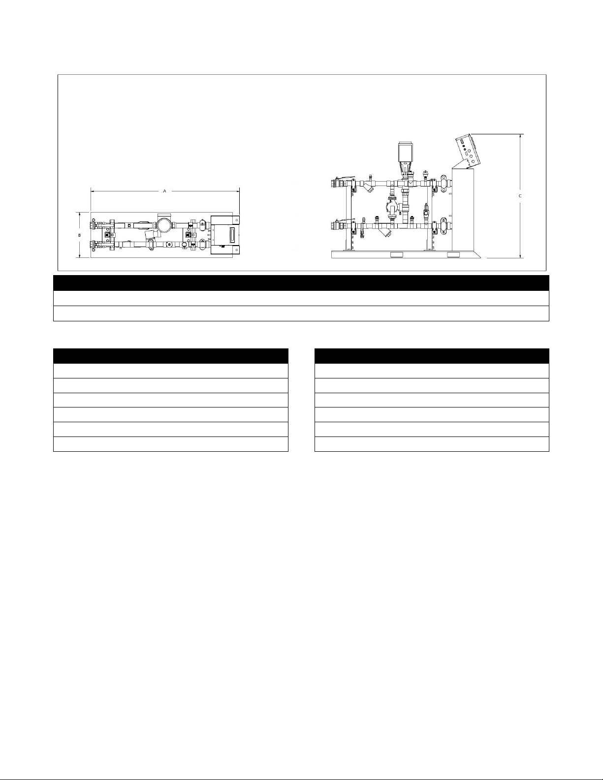
1.3.3 –Dimensions and Connections .....................................................................................................................................................................3
1.4 –Sequence of Operation....................................................................................................................................................................................4
1.5 –Codes .................................................................................................................................................................................................................4
1.6 –Warranty ............................................................................................................................................................................................................4
Part 2 –Installation..................................................................................................................................................................4
2.1 –Checking the Equipment.................................................................................................................................................................................4
2.2 –Mechanical Environment.................................................................................................................................................................................4
2.3 –Locating the Equipment ..................................................................................................................................................................................4
2.4 –Clearances.........................................................................................................................................................................................................4
Part 3 –Heat Exchanger ..........................................................................................................................................................4
3.1 –Overview............................................................................................................................................................................................................4
3.2 –Double Wall Models..........................................................................................................................................................................................5
3.3 –Cleaning.............................................................................................................................................................................................................5
Part 4 –Electrical.....................................................................................................................................................................5
4.1 –Overview............................................................................................................................................................................................................5
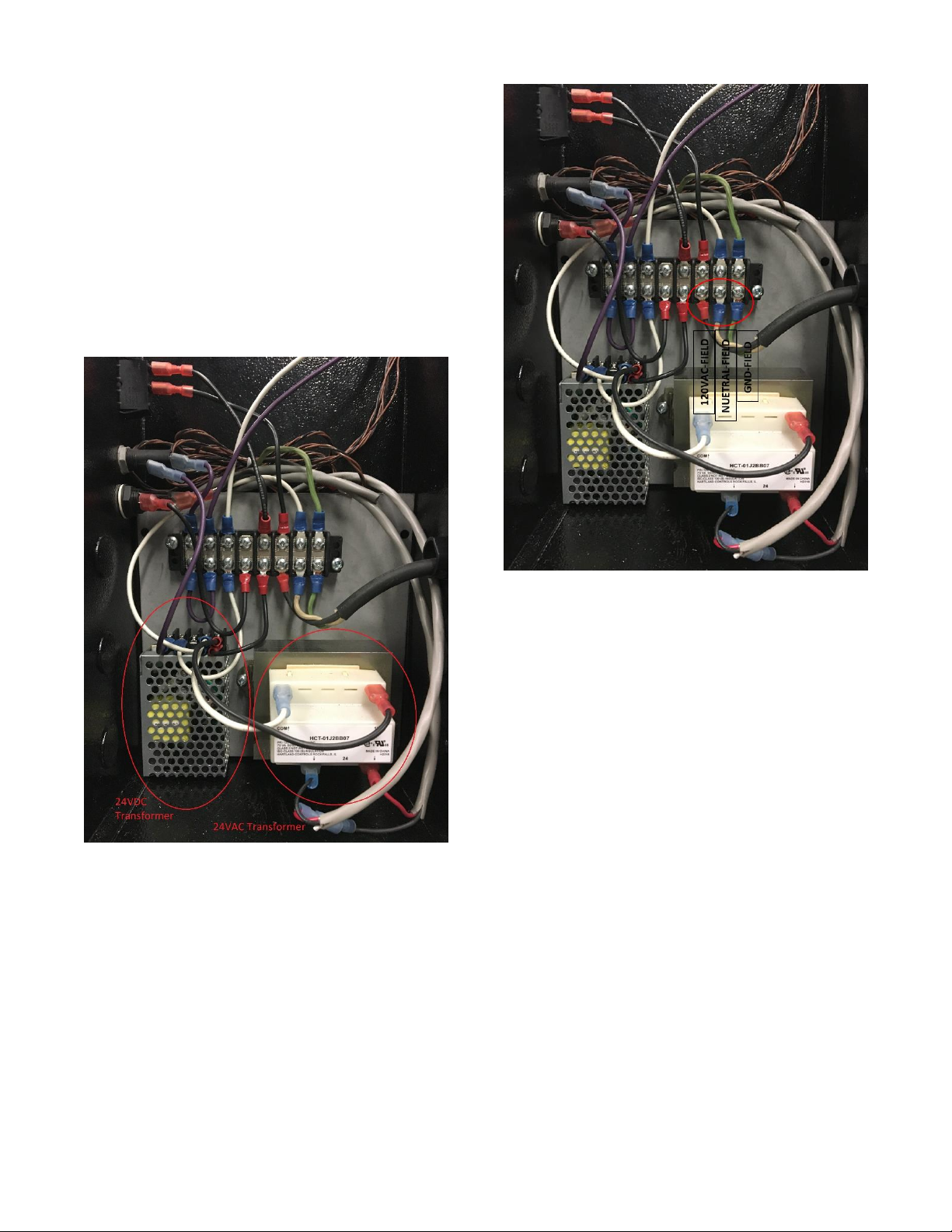
4.2 –Field Power Supply ..........................................................................................................................................................................................6
4.3 –Fuses..................................................................................................................................................................................................................6
4.4 –Digital Output Wiring .......................................................................................................................................................................................7
Part 5 –Control........................................................................................................................................................................8
5.1 –Overview............................................................................................................................................................................................................8
5.2 –Screen Navigation ............................................................................................................................................................................................9
5.2.1 –<Control>......................................................................................................................................................................................................11
5.2.2 –<Alarm>.........................................................................................................................................................................................................11
5.2.3 –<Setup> (Installer Level Password: 3232)................................................................................................................................................12
5.2.3.1 –<Alarm Configuration> ............................................................................................................................................................................12
5.2.3.2 –<Data Logging> ........................................................................................................................................................................................13
5.2.3.3 –DataXport...................................................................................................................................................................................................14
5.2.3.3 –<Modbus>..................................................................................................................................................................................................16
5.2.3.4 –<PID Configuration>.................................................................................................................................................................................16
Part 6 –Components .............................................................................................................................................................17
6.1 –Electro-Hydraulic Actuator............................................................................................................................................................................17
6.1.1 –Operation......................................................................................................................................................................................................17
6.1.2 –Stroke Calibration........................................................................................................................................................................................17
6.1.3 –Manual Operation ........................................................................................................................................................................................17
6.2 –Temperature and Pressure Relief Valve (If Supplied) ...............................................................................................................................17
6.2.1 –Overview.......................................................................................................................................................................................................17
6.2.2 –Re-inspection of T&P relief valve..............................................................................................................................................................18
6.3 –Aquastat (Manual Reset) ...............................................................................................................................................................................18
6.4 –Circulator Pump..............................................................................................................................................................................................18
6.4.1 –Overview.......................................................................................................................................................................................................18
6.4.2 –Troubleshooting ..........................................................................................................................................................................................20
Appendix A –Special Considerations for low volume boilers dedicated only to a DHW load.............................................21
Appendix B –Electrical Schematics –DynaFLO...................................................................................................................22
DynaFLO LIMITED WARRANTY.............................................................................................................................................23

1
Part 1 - General Information
1.1 –Special Instructions to Owner
This manual supplies information for the installation, operation and servicing of the appliance. It is strongly recommended that
this manual be reviewed completely before proceeding with an installation.
NOTE: RETAIN THIS MANUAL FOR FUTURE REFERENCE
WARNING
IMPROPER INSTALLATION, ADJUSTMENT, ALTERATION, SERVICE OR MAINTENANCE can cause injury or property
damage. Refer to this manual. For additional information, consult a qualified installer, service agency or gas supplier.
DO NOT
Do not use this appliance if any part of it has been under water. The possible damage to a flooded appliance can be extensive
and present numerous safety hazards. Any appliance that has been under water must be replaced.
DO NOT
Do not turn this appliance on unless the pipes are filled with water, failure to do so will damage the circulator pump.
IMPORTANT
Consult and follow local Building and Fire Regulations and other Safety Codes that apply to this installation. Contact the local
gas utility company to authorize and inspect all gas and flue connections. Installation and service must be performed by
CAMUS qualified factory trained service technicians.
Boilers and water heaters are heat producing appliances. To avoid damage or injury, do not store materials against the appliance
or the vent-air intake system. Use proper care to avoid unnecessary contact (especially children) with the appliance and vent-air
intake components.
Never cover your appliance, lean anything against it, store trash or debris near it, stand on it or in any way block the flow of fresh
air to your appliance.
UNDER NO CIRCUMSTANCES may flammablematerials such as gasoline or paint thinner be used or stored in the vicinity of this
appliance, vent-air intake system or any location from which fumes could reach the appliance or vent-air intake system.
TO: Owners, Operators and/or Maintenance Personnel
This operating manual presents information that will help to properly operate and care for the equipment. Study its contents
carefully. Theunit will provide good service andcontinued operation if proper operating and maintenance instructions are followed.
No attempt should bemade tooperate the unituntil theprinciples of operation andall of thecomponents arethoroughly understood.
It is the responsibility of the owner to provide training and advice in all aspects of safety not only to his or her personnel, but to any
contractors' personnel who will be servicing, repairing, or operating the equipment.
CAMUS equipment is designed and engineered to give long life and excellent service on the job. The electrical and mechanical
devices supplied as part of the unit were chosen because of their known ability to perform; however, proper operating techniques
and maintenance procedures must be followed at all times.
Any “automatic” features included in the design do not relieve the attendant of any responsibility. Such features merely eliminate
certain repetitive chores, allowing more time for the proper upkeep of equipment.
It is solely the operator’s responsibility to properly operate and maintain the equipment. No amount of written instructions can
replace intelligent thinking and reasoning and this manual is not intended to relieve the operating personnel of the responsibility
for proper operation. Onthe other hand,a thorough understanding of thismanual isrequired beforeattemptingto operate, maintain,
service, or repair this equipment.
Operating controls will normally function for long periods of time and we have found that some operators become lax in their daily
or monthly testing, assuming that normal operation will continue indefinitely. Malfunctions of controls lead to uneconomical
operation and damage and, in most cases, these conditions can be traced directly to carelessness and deficiencies in testing and
maintenance.
The operation of this equipment by the owner and any operating personnel must comply with all requirements or regulations of the
insurance company and/or other authority having jurisdiction. In the event of any conflict or inconsistency between such
requirements and the warnings or instructions contained herein, please contact CAMUS before proceeding.

2
1.2 –Product Overview
DynaFLO is a prefabricated product mounted on a skid that provides controlled heat exchange between a boiler loop and a
DHW (domestic hot water) loop. Heat is extracted from the boiler loop and through a very compact and efficient stainless steel
brazed plate heat exchanger is transferred to the cold domestic water supply. Each DynaFLO model has been designed for an
application with specific flow and temperature ranges on the DHW side as well as the boiler side.
All DynaFLO models come with a color digital display touch-screen control, DHW outlet temperature transmitter, anti-scaling
circulator, isolation valves, drain valves, Victaulic for easy removal of heat exchanger, strainers, lead free pressure relief valve
or lead-free temperature and pressure relief valve (Optional), air-vent, high limit switch, and a very precise electro-hydraulic 3-
way actuator that can be turned into a 2-way operation. If your DynaFLO model is equipped with the IntelliFLO option your
DynaFLO will also have a flowmeter installed on the DHW inlet.
To avoid any confusion throughout this manual, an image labelling each pipe is provided below:
1.3 –Product Ratings
1.3.1 –Capacity Ratings
MAWP, DHW Side [PSI]
MAWP, Boiler Side [PSI]
150
150
1.3.2 –Electrical Ratings
Voltage
Max. Amp. Draw
Connectivity
Analog Inputs
Analog Outputs
Digital Outputs
110-120V/1/50-60Hz
3 Amps
1 X Modbus RS-485 Port
(Port 2 located on PLC)
1 X USB (For Data
Logging or Software
Updates)
1 X RTD
DHW Outlet temperature
1 X 4-20mA
Flowmeter (If provided)
1 X 4-20mA
Electro Hydraulic
Actuator
1 X Remote Alarm/Contact
1 X Alarm Indicator/Lamp

3
1.3.3 –Dimensions and Connections
Camus Model
A
B
C
S1-S5; D1-D3
52-1/2”
16”
44”
S6; D4-D6
58-1/4”
16”
44”
Camus Model
Outlet Connections
Camus Model
Outlet Connections
DOWB-S1-
1.5" FNPT
DOWB-D1-
1.5" FNPT
DOWB-S2-
1.5" FNPT
DOWB-D2-
1.5" FNPT
DOWB-S3-
2" FNPT
DOWB-D3-
2" FNPT
DOWB-S4-
2" FNPT
DOWB-D4-
2" FNPT
DOWB-S5-
2" FNPT
DOWB-D5-
2" FNPT
DOWB-S6-
2" FNPT
DOWB-D6-
2" FNPT

4
1.4 –Sequence of Operation
1. Power is supplied as per Section 4.2
2. Theappliance isfilled with water (or a water-glycol
mixture) in all pipes and the heat exchanger.
3. The power switch is placed in the “ON” position.
120 VAC power is supplied to the control and
actuator transformers. 120 VAC is also applied to
the actuator.
4. The circulator installed on the DHW side starts
running.
5. The touch-screen digital display mounted on the
DynaFLO turns ON.
6. The built-in PID integrated in the control keeps
monitoring the DHW outlet temperature and
calculates the difference in value between the
DHW outlet temperature and the user selected set
point. It continuously attempts to achieve a
difference of 0 by modulating the electro-hydraulic
actuator thereby regulating the amount of heat
exchanged in the heat exchanger.
Please refer to Part 5 for more details about operation and
configuration of the control.
1.5 –Codes
The equipment shall be installed in accordance with
those installation regulations in force in the local area
where the installation is to be made. These shall be
carefully followed in all cases. Authorities havingjurisdiction
shall be consulted before installations are made. All
electrical wiring must be done in accordance with the
requirements of the authority having jurisdiction or, in the
absence of such requirements, with National Electrical
Code, ANSI/NFPA70 and/or the Canadian Electrical Code
part 1 CSA C22.1. Where required by the authority having
jurisdiction, the installation must conform to American
Society of Mechanical Engineers Safety Code for Controls
and Safety Devices for Automatically Fired Boilers, ASME
CSD-1.
1.6 –Warranty
Factory warranty (shipped with unit) does not
apply to units improperly installed or improperly
operated.
Factory warranty shall apply only when the
appliance is installed in accordance with local
plumbing and building codes, ordinances and
regulations, the printed instructions provided with
it and industry best practices.
Excessive water hardness causing a scale
buildup in the stainless steel heat exchanger or
pipes is not a fault of the appliance and is not
covered by warranty. Consult the factory for usage
recommendations in hard water areas.
Using or storing corrosive chemicals in the
vicinity of this appliance can rapidly attack the
stainless steel tubes and coils and voids warranty.
Damage caused by freezing or dry firing voids
warranty.
The manufacturer shall NOT be held liable for any
personal injury or property damage due to
condensation of any exterior part of the appliance
including pipes.
Part 2 –Installation
2.1 –Checking the Equipment
Check for signs of shipping damage upon receiving
equipment. Pay particular attention to parts accompanying
the appliance, which may show signs of being hit or
otherwise being mishandled. Verify total number of pieces
shown on packing slip with those actually received. In case
there is damage or a shortage, immediately notify carrier.
2.2 –Mechanical Environment
Install this appliance in a clean, dry location with adequate
air supply.
The mechanical room MUST NOT be used to store
corrosiveor flammable chemicals, such as gasoline or paint
thinner. Such chemicals must not be stored in the vicinity of
this appliance. Chillers or other equipment utilizing
refrigerant should also not be installed in the same
mechanical room as fuel burning appliances.
2.3 –Locating the Equipment
The appliance should be located close to a floor drain in an
area where leakage from the appliance or connections will
not result in damage to the adjacent area or to lower floors
in the structure. Under no circumstances is the
manufacturer to be held responsible for water damage in
connection with this unit, or any of its components.
2.4 –Clearances
This appliance is suitable for installation with minimum
clearances to combustibles as follows:
Table 1: Clearances From Combustibles
Clearances, All Models
Top
12" (30cm)
Sides
12" (30cm)
Rear
12" (30cm)
Part 3 –Heat Exchanger
3.1 –Overview
The heat exchanger installed in the DynaFLO is a very
compact assembly composed of stainless steel plate packs
sealed together by means of brazing metal (Copper) along
the border of the units. This eliminates the need for
traditional gaskets or external pressure retaining parts. All
of theheat exchangers used in DynaFLO models are ASME
certified, have CRN and are NSF 372 certified. The plate
packs making up the heat exchanger have special
corrugation patterns that promote turbulent flow which in
turn dramatically increases rate of heat transfer. Regular
maintenance and cleaning of the heat exchangers are
required. The manufacturer is not responsible for damages

5
caused by lack of cleaning and maintenance of the heat
exchanger. This appliance is equipped with victaulics on all
connection points to the heat exchanger for easy removal
of the heat exchanger for maintenance and cleaning.
3.2 –Double Wall Models
The design of the double wall brazed plate heat exchanger
prevents cross contamination of fluid streams if there is an
internal leak within the fluid. Two stainless steel plate walls
separate the fluid streams, with an air gap in between. In
the event of a leak, the affected fluid will flow in the air gap
and escape out of the heat exchanger, enabling visual
detection of the leak.
The double-wall models are designed to minimize the risk
of cross contamination by allowing for visual notice of
internal leak(s) –prompting the user to take action before
the issue propagates. In the event that a failure is left
undetected, and the product not promptly removed from
service, the structural integrity of the product may become
compromised, resulting in further damage to the product.
The user is responsible for systematic and periodic
monitoring of the product to detect potential leaks –
failure to do so defeats the purpose of the double-wall
design.
3.3 –Cleaning
As previously mentioned, the heat exchangers used in all
DynaFLO models have special corrugation patterns that
promote turbulent flow. As a result, the heat exchangers
operate with high turbulence flow, even at low flow rates.
This high turbulence keeps small particles in suspension
minimizing fouling and scaling. However, in some
applications the fouling tendency can be very high (e.g.
using extremely hard water at high temperatures). In such
cases, it is always possible to clean the heat exchanger by
circulating a cleaning liquid. All DynaFLO models are
equipped with Victaulics right downstream of each heat
exchanger inlet and outlet connection. The Victaulics allow
for easy removal of the heat exchanger for cleaning:
1. Before shutting off the unit close the portion of the
boiler loop leading to the boiler side of the
DynaFLO while letting the domestic side run for 5
to 10 minutes. This will cause the cold domestic
supply totakeaway any heat left ontheboiler side
before shutting down.
2. Once the heat exchanger has cooled down, close
down the domestic supply to DynaFLO.
3. Turn off the DynaFLO by switching the power
button.
4. Drain the unit by using the drain valves provided
on DynaFLO.
5. Remove the Victaulics.
6. Remove the heat exchanger shroud
7. Slowly remove the heat exchanger while sliding it
on the built-in stool inside the heat exchanger
cabinet.
8. Usea tank with a descaling solutionthat issafe for
domestic water applicationsandis compatible with
stainless steel, copper, brass and bronze.
9. Pump the cleaning liquid through the heat
exchanger. For optimum cleaning, the cleaning
solution flow rate should be a minimum of 1.5
times the normal flow rate, or as per the table
below, preferably in a back-flush mode.
Recommended Flow for Effective Back-Flush Mode
Model
Flow (GPM)
Single Wall
DOWB-S1-
19
DOWB-S2-
20
DOWB-S3-
38
DOWB-S4-
46
DOWB-S5-
53
DOWB-S6-
59
Double Wall
DOWB-D1-
12
DOWB-D2-
25
DOWB-D3-
31
DOWB-D4-
43
DOWB-D5-
54
DOWB-D6-
63
Note: Flow can deviate from the nominal value on the table
10. After use, do not forgetto rinsethe heat exchanger
carefully with clean water.
11. Only use chemicals which do not attack copper
and stainless steel. Consult a cleaning specialist
in case of doubt.
Part 4 –Electrical
4.1 –Overview
***See Electrical Schematics in Appendix B***
The appliance, when installed, must be electrically
grounded in accordance with the requirements of the
authority having jurisdiction or in the absence of such
requirements, with the latest edition of the National
Electrical Code ANSI/NFPA No. 70. When the unit is
installed in Canada, it must conform to the Canadian
Electrical Code, C22.1, Part 1 and/or local Electrical Codes.
All wiring between the appliance and field installed devices
shall be made with wire having minimum 220ºF (105ºC)
rating. Line voltage wire external to the appliance must be
enclosed inapproved conduit or approved metal clad cable.
To avoid serious damage, DO NOT ENERGIZE the
appliance until the pipes are full of water. Ensure that all air
is removed from the pump housing and piping before
beginning initial operation. Provide the appliance with
proper overload protection.
WARNING
THIS PRODUCT MUST BE PROPERLY GROUNDED
BEFORE ANY ELECTRIC CURRENT IS APPLIED TO
THE BLOWER OR CONTROLS!

6
This appliance uses two transformers to supply a low DC
voltage circuit for energizing the control as well as a low AC
voltage to energize the actuator. The voltage on the
secondary side of the DC transformer should be 24 VDC
when measured with a voltmeter. The voltage on the
secondary side of the AC transformer should be 24 VAC. A
3.3A circuit breaker is provided on the secondary sideof the
AC transformer. A tripped circuit breaker indicates a short
in the 24VAC energizing the actuator and must be
corrected.
The 24VDC transformer that energizes the control is
located insidethecontrol boxon thebottom left. The24VAC
transformer which energizes the actuator is located inside
the control box on the bottom right. They can be seen in the
image below:
4.2 –Field Power Supply
The main field 120VAC power supply can be inserted
through the knock-out holes that are placed on the sides of
the control box mounted on top of the heat exchanger
cabinet. This connection must be made by a licensed
electrician, when the unit is not energized, and in
accordance with section 4.1 of this manual. A strain relief
should be used. The connections should be made to the
terminals that are shown in the image below (the product
will have actual labels on the electrical mounting plate):
4.3 –Fuses
The DynaFLO is equipped with two fuses. One is to protect
the pump and the other fuse is to protect the controller.
These two fuses are shown in the image below. The fuse
holder on the top contains a glass cylinder 1Amp fuse that
protects the controller. The fuse holder on the bottom
containsa bigger glass cylinder fuse that is rated for 2Amps
which protects the pump.

7
4.4 –Digital Output Wiring
The controller mounted on the DynaFLO is equipped with
two digital relay outputs that are programmed to open and
close in relation to alarms. O0 (Output0) and O1 (Output1)
could be located on the bottom of the controller. O0 is
intended to be used for closing a circuit that energizes an
alarm lamp or indicator. This contact will continuously open
and close if there is an active unacknowledged alarm,
remains closed whenever there is an acknowledged active
alarm and opens whenever there are no alarms. More
details about alarms are explained in section 5.2.2.
O1 on the other side is intended to be used with remote
systems such as aBMS(Building Management System), or
a building alarm panel as this contact is either continuously
ON whenever there is an active alarm (regardless of
acknowledged or not) or continuously OFF whenever there
are no alarms. This is to protect other contacts or electrical
systems that might be present in a remote system circuit.
The electrical specifications of the relays can be seen
below:
Depending on thetype ofload and circuit that O0 and/or O1
are intended to switch ON and OFF, power up to either
30VDC MAX. or 250VAC MAX. needs to be provided to
terminal 15 as shown in the next figure while conforming to
electrical specifications in the above table. More details
about the wiring can be seen in Appendix B.
Increasing Contact Life Span:
To increase the life span of the relay output contacts and
protect the device from potential damage by reverse EMF,
connect:
A clamping diode in parallel with each inductive
DC load.
An RC snubber circuit in parallel with each
inductive AC load.

8
Part 5 –Control
5.1 –Overview
The controller mounted on the DynaFLO is equipped with a
4.3” touch-screen display as well as built-in I/O, networking
and data-logging capability. The controller constantly
monitors the outlet temperature of the DHW (Domestic Hot
Water) side through an accurate 3 wire RTD. Based on the
feedback from the outlet RTD it then sends a signal to the
3-way electro-hydraulic actuator that’s on the boiler side to
regulate the amount of heat coming through the heat
exchanger. The controller does this modulation on a
continuous basis based on a PID loop such that the outlet
temperatureon theDHW sideremains within+/-1°Fofuser-
selected set point in steady-state conditions. The PID
parameters that define theway the controller modulates are
protected by a factory level password. The default
parameters have been fine-tuned after extensive testing
and it is recommended not to change them. The image
below demonstrates the relationship between the controller
and other components:
For alarms, the controller also has a digital output (O1) that
is programmed to turnON and stay ON once there is a new
alarm, this output could be used for remote operations. The
controller also has another digital output (O0) that starts
switching ON and OFF once there is a new alarm, this
output could be used with a flashing lamp. More details
about digital alarm outputs are explained in 5.2.2 and 5.2.3.
The Controller has a Modbus (RS-485) port for
communications. Port 2 (shown in the image below) allows
communication with a Modbus Master such as a BMS. A
Modbus Master can read and write the set point, get alarm
notifications and clear alarms, directly control the actuator
and etc. More information about the parameters that can be
accessed by aModbusMaster is given in section 5.2.1.The
Modbus Map table on the following page lists all the
parameters that can be accessed by a Modbus Master.
Port 2 is a RJ11 type connection, 6POS2C (A and B
signals).

9
WARNING!
MODBUS MASTER SHALL NOT WRITE INTO ANY REGISTER THAT IS NOT INCLUDED IN THE ABOVE TABLE!
* Note: DynaFLO’s PLC’s Registers are 0-based thereby for e.g. MI0 = Modbus 40001 (Unless the Modbus software also uses
its own offset in which case the specific software has to be consulted.)
** Note: These commands are for reference only as each Modbus software has a different interface with different options and
ways of converting commands.
5.2 –Screen Navigation
The chart below shows the controller’s menu structure.
The start-up screen lists three options, <Control>, <Setup>
and <Alarm>. Each option is explained in the next section. On
the top right there is a display that indicates that status of
alarms.
Thecontroller uses a two-tiered password protection scheme.
The low level password is needed to access the Setup menu.
The higher level password is needed for configuring the P, I
and D parameters as these parameters are no recommended
to be changed.
Modbus Map
Parameter
Register*
Traditional
Modbus
Reference**
Read/Write
Notes
16 Bit Registers
40010
R
DHW Out Temp. Read
MI 9
Set Point Read
MI 97
40005
R
Actuator Position (%) Read
MI 95
40096
R
Set point Write
MI 87
60088
W
Only Possible when the
control is set to Remote
Setpoint
Actuator Position Write (%)
MI 96
60097
W
Only Possible when the
control is set to Remote
Direct
Memory Bits
10024
R
Low Temp. Alarm Active Notifier
MB 23
High Temp. Alarm Active Notifier
MB 26
10027
R
RTD1 Alarm Active Notifier
MB 29
10029
R
AI1 Failure Alarm Notifier
MB 35
10036
R
Low Battery Alarm Notifier
MB 38
10039
R
One or more Alarms is Active
MB 20
10021
R
Clear All Pending Alarms and Rescan
MB 19
50020
W
If all conditions for all
alarms have been satisfied,
this can ACK any pending
alarm that is not active
anymore. However, this
also clears such alarms
from alarm history.

10
Start-up Display
Setup
(Password Required:
3232)
Alarm
Configuration
Data Logging
Modbus
PID
Configuration
Flowmeter Calibration
(Factory Level
Password Required)
PID Parameters
(Factory Level
Password Required)
Control Alarm

11
5.2.1 –<Control>
In the Control screen all the necessary information about
the instantaneousperformanceof DynaFLO can beviewed.
<DHW Outlet Temp.> displays the reading from the RTD
sensormountedontheoutlet (bottom pipe) of theDHW side
of DynaFLO. <Setpoint> is a touch-screen display that
shows the current user-selectable setpoint which could be
changed by just touching it. This setpoint sets the target
temperature of the DHW outlet. The control will modulate
the actuator to regulate the amount of heat that is allowed
to enter the heat exchanger in order to always keep the
DHW outlet temperature within +/-1°F in steady-state.
NOTE
IF THE CONTROL IS SET TO OPERATE IN ANY
<Remote> MODE <Setpoint> CANNOT BE
CHANGED FROM THE SCREEN.
When the control is in <Remote_Direct> or <Remote_SP>
mode, the setpoint can only be changed by sending a
Modbus command from a master. The <Actuator Position>
displays the position of the three-way electro-hydraulic
actuator mounted on the boiler side of the DynaFLO. This
position is displayed in percentage. 100% means the
actuator is fully open, 0% means the actuator is closed and
the heat exchanger is bypassed. This display is greyed out
in all modes except in <Local_Manual>. As mentioned
before, the PID loop keeps comparing the outlet
temperature to the target setpoint, and it outputs a signal to
the actuator correspondingly. However, when in
<Local_Manual> the automatic function of the built-in PID
is bypassed and user can manually control the position of
the actuator. In that case the <Actuator Position> display
stops being greyed out to indicate that the actuator is not
being controlled by the local built-in PID. In that case the
user can insert the position by simply touching the
<Actuator Position> display.
On the right hand side under “Control Mode” there are four
options. The four options are generally distinguished by
whether the performance is controlled locally by the PLC or
remotely through Modbus. When control is in
<Local_Manual> or <Local_Auto> important parameters
vital to maintaining the target DHW outlet temperature such
as PID, setpoint and actuator’s position can be configured
locally from the touch-screen. However when
<Remote_Direct> or <Remote_SP> is selected, those
parameters can only be configured by sending Modbus
commands.
The first option, <Local_Manual> as mentioned bypasses
the local built in PID and makes the <Actuator Position>
display touch accessible such that the user can control the
actuator by inserting the position into this display. This
could become useful in calibrating or troubleshooting the
actuator.
<Local_Auto> will disable the touch accessibility of the
<Actuator Position> (display becomes greyed out). In this
case the local built-in PID controls the actuator position and
<Actuator Position> just displays the current position of the
actuator that is being changed by the built-in PID on the
control. The performance of the built in PID is controlled by
<P> for proportional, <I> for integration, and <D> for
derivative that are located in < PID Parameters> in <PID
Configuration> in <Setup>. However access to these
parameters is only available with a factory level password
as these parameters are not recommended to change.
<Remote_Setpoint> is similar to <Local_Auto> in a sense
that the local built-in PID integrated in the control operates
the actuator position and thereby maintaining the target
outlet temperature. While the local PID on the control is
being used, the <Setpoint> becomes greyed out since it is
configured by a Modbus command sent from a Modbus
Master.
The alarm indicator display located on the top right corner
of the screen indicates the status of alarms. If there is an
active alarm that is not yet acknowledged, the display
shows <Unack’d Alarm>. In this case going to the <Alarm>
screen located on the Start-Up display shows the details of
active alarms at which point they could become
acknowledged. More details regarding alarms are
explained in the next section. If active alarms are
acknowledged the alarm indicator displays <Ack’d Alarm>,
if there are no active alarms the indicator displays <No
Alarms>.
5.2.2 –<Alarm>
The <Alarm> screen displays active alarms, regardless of
whether they are acknowledged yet or not. Details about
each specific active alarm is shown in the “Alarm Details”
screen, details such as name of the alarm, priority level,
time of trigger and whether the alarm is acknowledged or
not. Unacknowledged alarms will appear with an “Ack”
button on the bottom left corner of the screen. Pressing the

12
“Ack” button will acknowledge the alarm. Pressing “ESC”
takes the user through two more screens, namely “Alarms
in Group” and “Groups with Pending Alarms”.
“Alarms in Group” lists a summary of all the alarms active
in DynaFLO in one page, if there is more than one active
alarm. However this page does not go into as much detail
for each alarm as “Alarm Details” page.
“Groups with Pending Alarms” would show all the groups of
alarms that have an active alarm, however in DynaFLO all
alarms are under Group 00 and therefore this alarm page
will always only list Group 00if thereis ever an active alarm.
Pressing the “ESC” button one more time from here will
then take the user back to the Start-Up screen.
Alternatively through the registers listed in Modbus Map
tablein section 5.1, a Modbus MasterIs notified about each
specific alarm in the group that is triggered. The Modbus
Master is also notified if in general there is one or more
active alarms. The Modbus Master can also ACK and Clear
all alarms provided that all the conditions of triggering the
alarms are satisfied. If not satisfied, even if Modbus Master
acknowledges and clears the alarms, the alarms show up
again instantaneously since the condition that triggered
them is not yet satisfied. It should be noted that if Modbus
Master acknowledges and clears alarms, alarms are also
cleared from the <Alarm History> which is explained in the
next section. The correspondingregisters relating to alarms
are tabulated in the Modbus Map table in section 5.1.
As mentioned in section 4.4, two digital outputs are
associated with alarms, O0 and O1. Whenever there is an
active alarm, regardless of the alarm acknowledged or not,
O1 will come on and it will stay on for as long as the new
alarm remains active even if it becomes acknowledged, O1
will go off when alarm is satisfied. This digital output is
suitable for use with remote systems such as a BMS
(Building Management System) or with a building alarm
panel, buzzers or etc. O0 however will switch between ON
and OFF whenever there is a new unacknowledged alarm.
And once the alarm is acknowledged it turns to a solid ON.
And once the alarm is satisfied it will go OFF. This output is
therefore recommended for connecting to an alarm light to
follow the sequence that was just described. The electrical
wiringof thesetwo digital outputsis explained insection 4.4
and in Appendix B.
5.2.3 –<Setup> (Installer Level Password: 3232)
5.2.3.1 –<Alarm Configuration>
When in <Alarm Configuration> low limit and high limit for
DHW outlet temperature can be selected. Once these
selections are made, <Setpoint> in <Control> cannot take
a value higher than <High Outlet Temp. Alarm> or a value
lower than <Low Outlet Temp. Alarm>. If the DHW outlet
temperature rises above the value chosen in <High Outlet
Temp. Alarm>, anew alarm will activateafter <Outlet Temp.
HL Time Delay> seconds. Similarly if the DHW outlet
temperature falls below the value chosen in <Low Outlet

13
Temp. Alarm>, a new alarm will activate after < Outlet
Temp. LL Time Delay > seconds. Should the DHW outlet
temperature fall back within the range set between <Low
Outlet Temp. Alarm> and <High Outlet Temp. Alarm>
before the time set in the time delays is reached, the alarm
will not activate.
Down from DHW outlet temperature high and low limit
alarms, pressing <Alarm History> will take the user to a
screen that shows details about the history of alarms:
While the <Number of Alarms in History> is a display that
shows the number of alarms currently held in <Alarm
History>, pressing <Clear Alarm History> will clear all
alarms in history turning <Number of Alarms in History> to
zero. It should be noted that a Modbus Master can also
clear alarms from the history provided that they are no
longer active. Please refer to Modbus Mapping table in
section 5.1.
5.2.3.2 –<Data Logging>
To use the data logging feature of DynaFLO’s controller a
computer, a softwarecalled DataXport anda USB cable are
needed.
DataXport allows the user to set automatic schedules for
data that has already been collected by DynaFLO’s
controller to be transferred to a computer. Once data has
been transferred to the computer onto DataXport, CSV,
Text or Excel files can be generated.
DataXport can be downloaded for free from:
https://unitronicsplc.com/software-visilogic-for-
programmable-controllers/
Instructions on how to use DataXport are given in the next
section.
Once DataXport is set up and DynaFLO’s controller is
connected to the computer using a USBcable, datalogging
can begin. On DynaFLO’s controller, the following
parameters are logged when <Data Logging ON/OFF> is
turned ON:
RTD1
Actuator Position
Setpoint
Total Number of Alarms Pending for
Acknowledgement
Date and Time
<Log Interval> allows the user to select the time interval for
logging data. Once <Log Interval> is set and <Data Logging
ON/OFF>is switched ON data is then collected onto a table
that is built into the controller’s internal memory. This table
has a 1000 rows, therefore depending on what the <Log
Interval> is set at, the table fills up. For example if the <log
Interval> is set at 1 second, after a 1000 seconds (16.66
minutes) the table fills up. If <Log Interval> is set at 60
seconds, table fills up after 60,000 seconds (16.66 hours)
and so on. Data is accumulated onto the built in table in
FIFO (First In First Out) which means that once the 1000
rows in the data table are filled up, the controller starts from
the beginning of the table again overwriting the values
previously stored in row 1.
Pressing <Clear All Logged Data> clears the built in data
table instantly, regardless of whether it is yet transferred to
DataXport or is filled up.
<Data Transfer In Progress> is an indicator that turns <In
Progress> when DataXport is in the middle of copying data
from DynaFLO’s built in data table in the controller. <Data
Transfer Complete> is another indicator that turns ON once

14
DataXport is finished with copying data from the built-in
data table in DynaFLO’s controller.
If the built-in data table in DynaFLO’s controller requires
more memory than what is available in the controller <On
Board Memory Status> will change from <OK> to <On
Board Memory Full>.
5.2.3.3 –DataXport
To build a DataXport project, you first define the project’s
modules listed below. These modules determine when the
data is logged, which data is logged, and how DynaFLO’s
controller can be accessed.
How to Access DynaFLO’s Controller:
“Ports” determine the parameters of the communication link
that is used by the PCrunning DataXportIn order to access
PLC and log data.
NOTE
The controller name must be identical to the name
assigned in the controller’s ladder application. This
name is: DynaFLO PLC
1. Select PC Ports from the Design Menu; PC Ports
window opens.
2. Double-click a line that corresponds to the COM
number that is used with the USB cable
connecting the PC to DynaFLO’s controller.
3. Make the desired selections as follows:
4. Click “OK” then “Close”.
When to Log:
The schedule determines the time intervals between data
log actions.
1. Select Schedules from the Design Menu.
2. Click Add to create a new schedule, click Edit or
double-click a line to redefine an existing
schedule, the schedule open.
3. Make the appropriate entries, then click OK to add
the schedule to the list.
What to log:
1. Select Tables from the Design Menu.
2. Click Add, then click on the Import Data Table
Structure button.
3. Name the Data Table Structure.
4. Read the structure from the PLC.
5. Select the Data Table Structure that was just read
from the controller under the name you chose.
6. Click “Close”.

15
7. Under “Data Table Structure” select the name you
chose.
8. Under “Table Name” you should see “Table 1”,
select “Table 1”.
9. Select “Read the entire table”
10. Select “MB to set” to “52”.
11. Click “Ok”. The table should now be listed in
“Tables”.
12. Click “Close” to close the “Tables” window.
Finalizing the project
1. Once all themodules havebeen set up, select Add
Site from the Design Menu; the PLC window
opens.
2. In the left-hand pane, for “PLC Name” enter:
DynaFLO PLC
3. Select the module parameters that you have
created displayed on the right-hand side of the
PLC window. Select desired schedules that you
have previously created.
4. Select the “PLC Type” as: Samba
5. Select “MB to Set” 51
6. Select the PC Port on your computer that is using
the USBcableconnected to DynaFLO’s controller.
7. Select “Enabled” to include this project/site when
DataXport project is run.
8. Select “Create Excel Files” so that DataXport
creates Excel files whenever a data log is created.
Note that DataXport creates a separate Excel file
for each data log.
NOTE
The controller name must be identical to the name
assigned in the controller’s ladder application as
describer in “How to access DynaFLO’s Controller”.
Otherwise the table will not be read from the controller in
this step.

16
1. Click OK, the project is now added and displayed
in the DataXport Design window.
Running the project
2. Select “Run Project” from the “Actions” menu,
(Save and name your project) DataXport begins
exporting the requested data via your defined port
and defined schedules.
3. You can also cause DataXport to enter “Run”
mode whenever the project is opened by selecting
that option from the “Actions” menu.
4. You can also force DataXport to enter “Run” mode
by selecting “Run Project” and then clicking the
“Force Call” button.
5.2.3.3 –<Modbus>
The user can assign a network ID or slave address to
DynaFLO’s controller by pressing <Network ID #> and
inserting a number.
When <Modbus ON/OFF> switch turns ON it opens Port 2
on DynaFLO’s controller and sets the controller as a
Modbus Slave with the following parameters:
Baud Rate: 19200
Data Bits: 8
Parity: None
Stop Bits: 1
Standard: RS485
A Modbus Master at this point can send commands to
DynaFLO’s controller based on section 5.2.1 and the
Modbus Mapping table in section 5.1.
5.2.3.4 –<PID Configuration and IntelliFLO>
The <Local PID ON/OFF> switch turns the built-in PID loop
in DynaFLO’s controller ON and OFF. This could become
handy for troubleshooting or to restart the local PID loop in
case it got stuck in what is called an integral wind down or
an integral windup; which may happen in case <Setpoint>
is suddenly changed by the user by a large amount.
PID Parameters> will take the user to a display that allows
the user to change the Proportional, Integral and Derivative
parametersthat govern the performance of the local built-in
PID loop. However these parameters have been fine-tuned
through extensive testing specifically for DynaFLO and
changing these parameters are not recommended as the
performance of the local PID loop is very sensitive to a
change in these parameters. Therefore access to this
screen requires factory level password which may only be
provided in special situations.
The <IntelliFLO> button enables/disables the IntelliFLO
(Patent pending) feature. Upon enabling IntelliFLO, the
controller proactively adjusts the actuator upon sensing
rapid DHW load changes to prevent temperature spikes. If
DHW flow is stable and IntelliFLO is still enabled, the main
fine-tuned feedback PID loop is still in charge of hundred
percent of the control. IntelliFLO is smart and automatic in
a sense that it is always watching the DHW load and it only
takes over control of the actuator in case there is a sudden
flow change. Once flow is stabilized again, IntelliFLO gives
the control back to the main feedback PID loop. As a result
there are no parameters to be adjusted by the installer or
the user, only to enable or disable the entire feature.
If your DynaFLO is not equipped with the optional IntelliFLO
technology, <IntelliFLO> should be switched to “Disabled”.
Under <Flowmeter Calibration>, a constant (K Factor) can
be adjusted to adjust the IntelliFLO’s flowmeter reading.
However factory should be consulted before changing this
constant as it is recommended to leave the constant
unchanged.

17
Part 6 –Components
6.1 –Electro-Hydraulic Actuator
6.1.1 –Operation
The Electro Hydraulic Actuator mounted on DynaFLO
requires a 24 VAC supply and a 4 to 20mA control signal to
proportionally control the actuator position. The actuators
mounted on DynaFLO have a 3/4-inch (20 mm) stroke. The
actuator communicates with the control through a 4 to 20
mA control signal. The actuator mounted on a valve,
produces a stroke proportional to the input signal. When
power is turned off or in the event of a power failure, the
actuator spring returnsthe valveto its closedlocation which
bypasses the heat exchanger.
6.1.2 –Stroke Calibration
To determine the stroke positions 0% and 100% in the
valve, calibration is required when the valve/actuator are
commissioned for the first time. The actuator must be
mechanically connected to a valve andmust have a 24VAC
power supply. The calibration procedure can be repeated
as often as necessary.
WARNING
Before starting calibration, be sure the manual adjuster
is set to automatic to register the actual values.
There is a slot on the printed circuit boards of the actuators.
To initiate the calibration procedure, the contacts insidethis
slot must be short-circuited, for example, with a
screwdriver. Automatic calibration can then proceed as
depicted in the following image:
Actuator runs to the 0 stroke position (1), green
LED flashes.
Actuator then runs to the 100 stroke position (2),
green LED flashes.
Measured values are stored in the EPROM.
Theactuator nowmoves to thepositiondefined by
control signal Y or Z (3), and the green LED now
glows steadily (normal operation).
Throughout this procedure, output U is inactive;
meaning, the values only represent actual
positions when the green LED stops flashing and
remains on continuously.
6.1.3 –Manual Operation
Turn the manual setting knob clockwise for
manual operation.
If a signal is sent to the actuator while it is in
manual operation, the actuator will move but the
control will not be accurate.
The valve cannot be commanded to its 0%
position while in manual operation.
6.2 –Temperature and Pressure Relief Valve (If
Supplied)
6.2.1 –Overview
The combined 2-in-1 temperature and pressure relief valve
mounted on DynaFLO provides proven means for
protection against both excessive temperature and
pressure in emergency conditions. It provides full automatic
temperature and pressure relief protection based on the
latest ANSI Z21.22 listing requirements for temperature
discharge capacity.
This manual suits for next models
13
Table of contents
Other Camus Hydronics Water Heater manuals
Popular Water Heater manuals by other brands

Crown Boiler
Crown Boiler DG-35 installation instructions

A.O. Smith
A.O. Smith LTE 66D instruction manual

Bosch
Bosch Evolution 500 Series Service bulletin

Savio
Savio Laser 14 S Instruction manual for installation and use

HCW
HCW MAHRW020W/P(03) Installation instructions manual

clage
clage GERMAN POOL DEN12 user manual

FLOWMAX Technologies
FLOWMAX Technologies 120 instruction manual

STIEBEL ELTRON
STIEBEL ELTRON wpf 20 Operation and installation

Ariston
Ariston GL 4 S user manual

Siemens
Siemens DH 12400DH 12401DH 18400 installation instructions

BOCK
BOCK 72E Installation operation & maintenance

STIEBEL ELTRON
STIEBEL ELTRON MEK-K Operation and installation manual