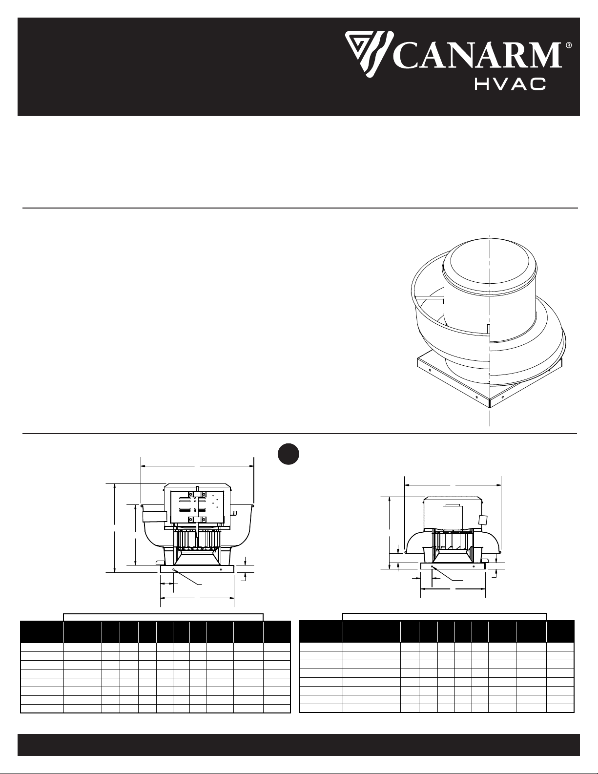
SÉRIES ALX
ÉVACUATEUR EN ALUMINIUM REPOUSSÉ
ALX-M-FR-06_27_22 Page 2 de 7
1. Tout le câblage doit être effectué par un électricien qualifié selon les Normes Électriques Nationaux et Locaux.
2. Assurez-vous quel le courant est fermé avant de procéder au câblage électrique.
3. Câbler le moteur selon le diagramme sur l’étiquette du moteur ou sur l’étiquette sur l’emballage du moteur. Tous les moteurs doivent
être câblés pour la même rotation qu’indiqué sur l’étiquette sur la plaque du haut.
4. Laissez une longueur suffisante de fil pour permettre un mouvement du moteur lorsque vous ajuster la tension de la courroie.
5. Cependant, le fil en trop doit être retenu pour prévenir qu’il entre dans la poulie, l’arbre ou la roue en mouvement.
6. Des interrupteurs d’arrêt sont recommandés et doivent être placés près du ventilateur afin de pouvoir les atteindre
rapidement en cas d’urgence et ainsi maintenir un contrôle électrique.
Vous pouvez varier le RPM sur certain moteur à une phase à entraînement direct à l’aide d’un contrôle à vitesse variable (communiquer
avec le manufacturier pour plus de détail). Le bouton du contrôle débute à la position fermé, puis peut être varier de grande à petite vitesse
par rotation du bouton. A la grande vitesse, le contrôle ferait fonctionner le moteur à son RPM maximum.
Tourner le bouton vers le bas régime réduira le RPM du moteur ainsi que le voltage.
Un ajustement de la vitesse minimum est requis pour limiter le minimum. Suivre ces procédures pour établir la vitesse minimum.
1. Le moteur doit être en état d’entretien pour permettre le réglage de la vitesse minimum. Le moteur ne se ralentirait pas à moins que
la charge appropriée y soit appliquée. Le RPM du moteur peut varier selon les différents systèmes (pression statique).
2. Tournez le bouton du contrôle à la position de vitesse la plus basse.
3. Déterminer et ajuster la vitesse minimum, il serait indiqué sur la boîte de contrôle elle-même
4. La plage de vitesse serait entre le RPM le plus grand et celui que vous venez d’établir.
Le voltage minimum le plus bas que vous pouvez appliqué sur les moteurs est 65VAC. Un voltage en deçà de ce niveau peut
causer un défaillance prématurée du moteur.
Pour un moteur 3 phases, un entraînement à fréquence varaible (VFD) est requis pour ajuster la vitesse du moteur.
CONTRÔLE DE VITESSE VARIABLE – UNE PHASE
ENTRAÎNEMENT À FRÉQUENCE VARIABLE – TROIS PHASES
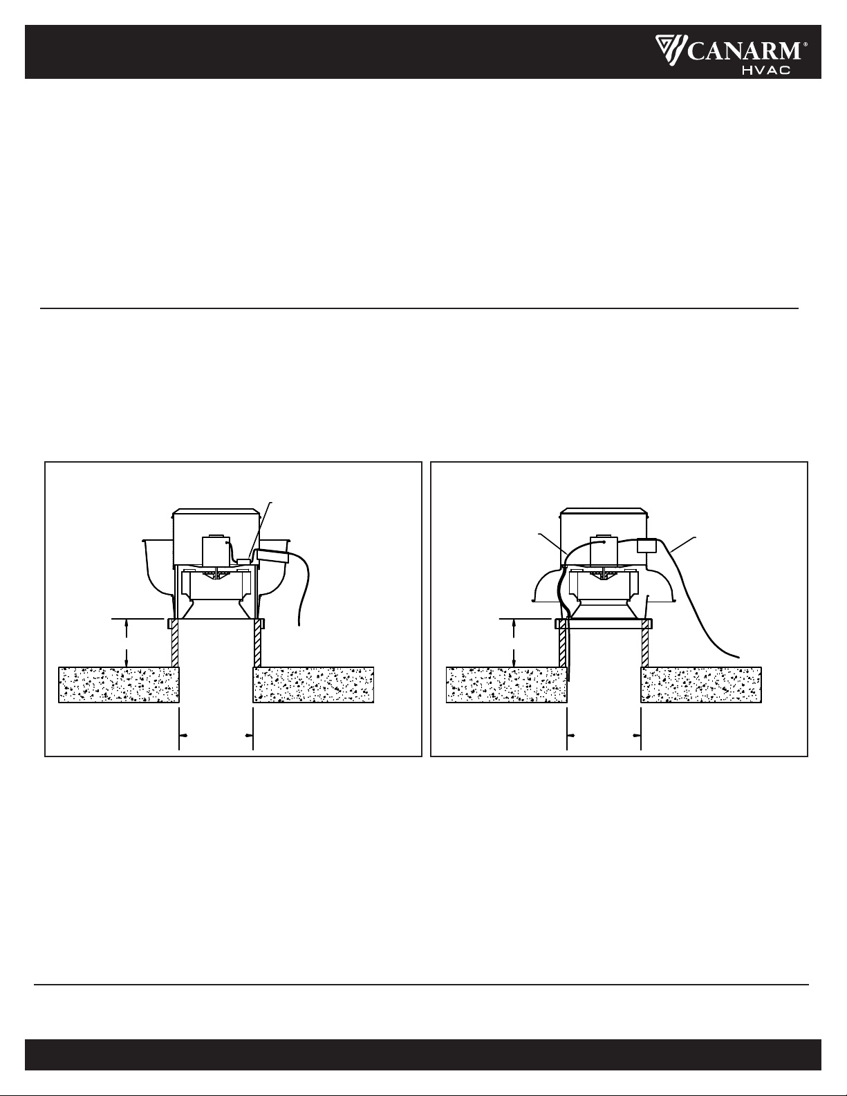
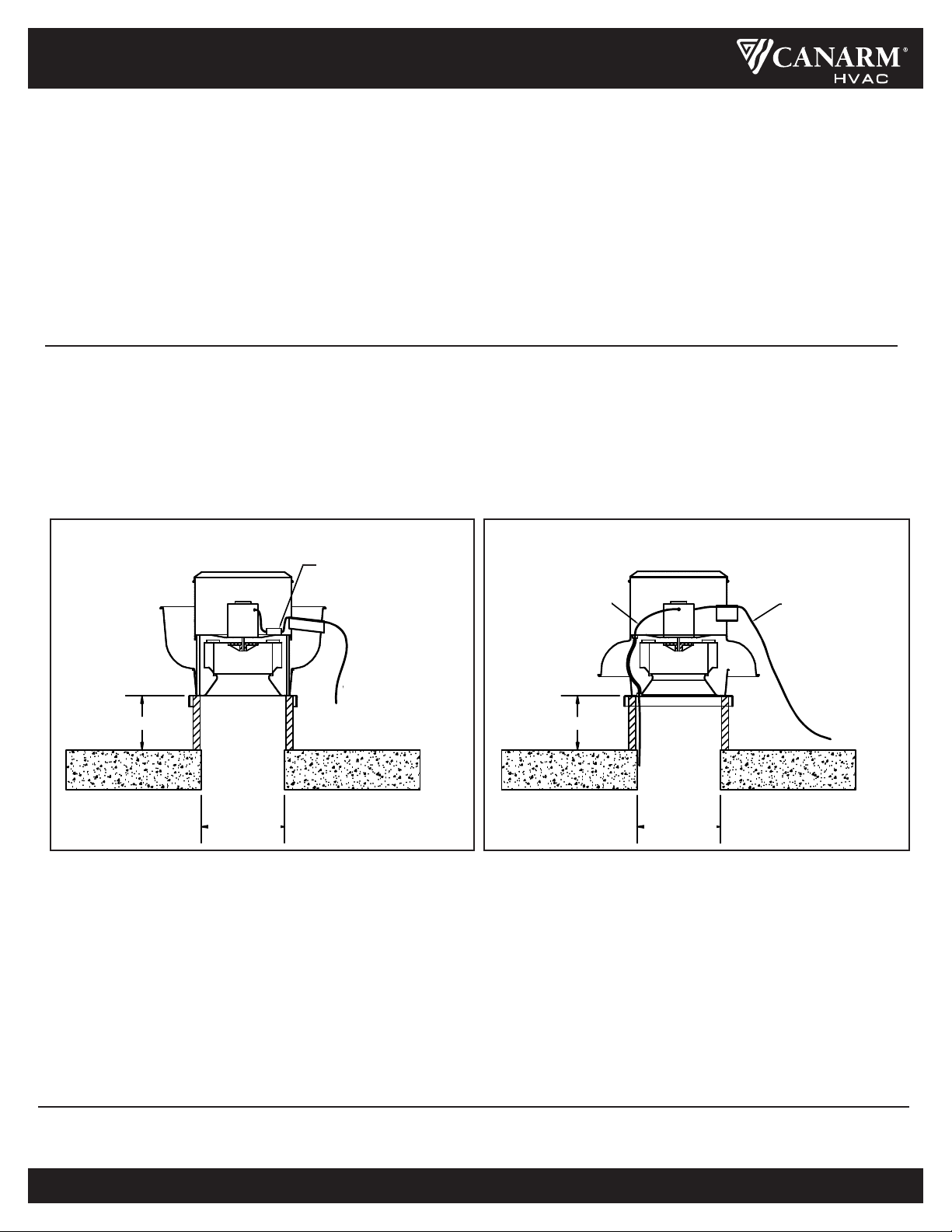
1. Posez le rebord, le scellant et la membrane pour assurer l’étanchéité.
2. Tournez la roue du souffleur à la main. La roue ne doit pas frotter contre le boîtier. Si il y a un frottement, dévissez la vis sur le
moyeu de la roue et déplacer la roue pour la dégager. Vissez les vis de nouveau.
3. Compléter toutes les connexions de conduits subséquents.
4. Poser le ventilateur au capot du rebord. Ne soulevez pas le ventilateur par le capot ou le moteur. Soulevez pasr les supports
horizontaux sur l’entraînement direct ou par la plaque de montage du moteur sur l’entraînement à courroie.
5. Utiliser au moins 8 attaches convenable pour posez le souffleur au rebord du toit.
6. Vérifier que le voltage utilisé est convenable pour l’appareil
7. Assurez-vous que la ligne n’est pas sous tension avant de procéder au câblage.
8. Retirer le capuchon du haut, posez le cable au moteur/interrupteur tel qu’indiqué.
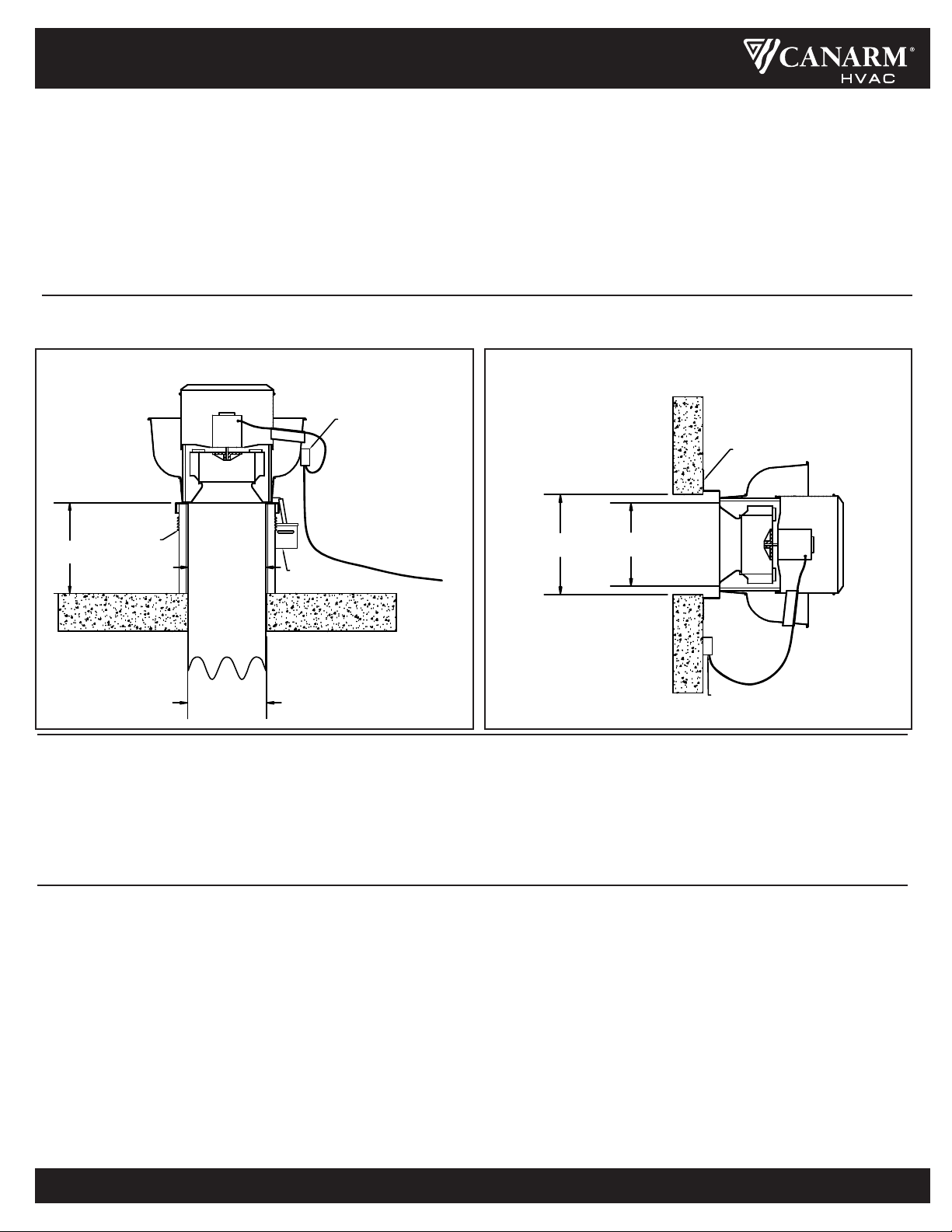
9. Pour les unités à débit vers le haut, le cable électrique entre au compartiment du moteur par le tube d’aération.
10. Assurez-vous que toutes les attaches et les vis sont serrées.
11. Remettre le capuchon du haut sur le capot.
12. Sceller correctement la base du ventilateur et du rebord afin d’assurer une bonne étanchéité.
INSTALLATION