CanaSafe TM 12 User manual

g
h
f
i
c
a
b
d
e
A = 110...165 cm
"F"=230 cm FULL BEAM RANGE
C = 139...221 cm
B = 325...368 cm
"G"=144cm LIMITED BEAM RANGE
A
B
T-lock
(3 pcs.)
locking trolley
work position
Beam
Detent pin U-bar
for quick beam-head lock.
Support Tripod
Trolley B
1 Person (EN795 class B)
Lifting loads: WLL=500kg
Trolley A
1 Person (EN795 class B)
Lifting Loads: WLL=1000kg
Spirit Level
Sliding Limiter Screw
Be sure to use when WLL
(Working Load Limit)
Exceed 500 kg.
Chain
Adjustable legs.
Seven positions.
(1) (2) (3)
Identity
Label
(5)
D = 139...191 cm
E =
150...
223 cm
Always use T-locks
to lock trolleys
working position
during lifting loads
(1)
Main Tripod
attachment
point
(EN795
class B)
(4)
Beam Attachment
Points
EN795 class B
personal protection only!
INSTRUCTION MANUAL - TM 12 SAFETY TRIPOD
DESCRIPTION READ CAREFULLY BEFORE USE THE EQUIPMENT
TM 12 safety tripod is a component of personal protective equipment against falls from height. TM 12 tripod is portable,
class B temporary anchor device and is used to protect employees (using Trolleys A or B, Main Tripod or Beam Attachment
Points) working in drainage wells, reservoirs, wells, silos, etc. during lifting loads (using Trolleys A or B or Main Tripod). For
personal protection tripod must be used in conjuction with fall arrest equipment. Tripod provides protection for two persons
simultaneously. The device complies with EN 795 class B.
Legs made of duraluminium profiles with rounded edges. They consist two sections. The telescopic construction of the legs
allows the user to adjust their length. To adjust the legs' length locking pins are used. The legs of the tripod are equipped
with self-aligning steel feet with rubber pads.
Total working load limit (WLL) is 1000kg
. Total weight of the tripod: 72kg. Tripod
working dimensions are shown below (legs fully extended...retracted) in cm.
Safety tripod TM12 consist of three separate elements:
Main tripod
(with three legs for lifting loads and personal protective
use),
Support Tripod
(with two legs) and
Beam
with trolleys (for lifting loads and personal protective use).
5 attachment points (EN 795 class B):
(1)
- Main Tripod Attachment Point,
(2)
- Trolley A,
(3)
- Trolley B,
(4)(5)
- Beam Attachment Points.
CONTENT OF THE IDENTITY LABEL
a) Device type.
b) Model symbol.
c) Reference number.
d) Number/year/class of the European standard.
e) CE marking and number of a notified body controlling
manufacturing of the equipment.
f) Month and year of manufacture.
g) Serial number of the tripod.
h) Caution: read the manual.
i) Marking of the manufacturer or distributor of the tripod.
Page 1 of 4
DETAIL A
LEVELING TRIPOD'S
BEAM
Always ensure that
the beam is true and
level used mounted
spirit level before use.
Improper leveling
may result in self
displacement the
load being lifted
along the beam
which can cause
injury to the operator!
DETAIL B
! PRECAUTIONS !
!
While working, pay attention to the chain, which fastens
the tripod legs, as it can cause accidental tripping of the worker.
!
The tripod must never be used without the leg chain in place.
!
Avoid working where the user may swing and hit an object or where
lines may cross or tangle with that of another worker in the area.
!
Fall arrest and rescue systems used with this tripod must meet applicable
EN standard requirements: (EN 795 - for anchor devices; EN 362 - for
connectors; EN361 - for full body harnesses; EN 360 - for retractable type
fall arresters; EN 1496 - for rescue lifting devices; EN1497 - for rescue
harnesses; EN 341 - for descender devices.
!
During installing Lifting Device RUP 503 Grip Locking Pin must be
embedded in locking hole. Only then Grip can be safely clamped on the
Outside Leg.
!
ALWAYS USE T-lock's to maintain Trolleys required position.
!
Total load can not exceed 1000 kg!
!
DO NOT use TM 12 safety tripod for more than two people
simultaneously!
! DO NOT connect 2 people to both Trolleys at the same time!
! DO NOT connect 2 people to both Beam Attachment Points at the
same time!
! ALWAYS USE Sliding Limiter Screw when Trolley A is used to lifting loads
(1000kg)!
! DO NOT use Beam Attachment Points for lifting loads!
(4) (5)
Producer:
edition: 4/29.05.2012
TM
CanaSafe
TM
CanaSafe www.canasafe.com
info@canasafe.com
TM
CanaSafe www.canasafe.com
info@canasafe.com

Main Tripod
Pulley
Figure 4
Figure 2
Grip
Grease with small amount of constant
lubricator Lever thread before install.
Locking
Pin
RUP 503
Lifting
Device
Reinforced
Leg
Locking
hole
Lifting device
PROPERLY
mounted on the
reinforced leg -
locking pin in the
socket.
Lifting device
IMPROPERLY
mounted on the
outside leg -
locking pin out of
the socket, based
on the leg.
INSTALLING A MAIN TRIPOD ONLY (Figure 1)
1.
Place the main tripod in an upright position on a flat, stable and hard
surface.
2.
Make sure the feet are on firm ground and can support the load.
3. Pull out the tripod legs to the desired length and lock with the locking
pin.
4.
Make sure the locking pins are properly secured. The end of the
locking pin must protrude above the surface of the tripod legs.
5.
Adjust the length of the legs so that the head is located in the
horizontal plane.
6.
The legs must always have the same length.
7.
The tripod should be positioned over opening so working line will be
located approximately in the center of the opening.
8.
Secure the tripod legs with the chain against the accidental sliding
open. The ends of the chain must be fastened with a snap hook. The
chain should be tight between the legs of the tripod. Remove excess
slack of the chain.
9.
To collapse main tripod pull leg down and swing the leg.
The tripod can be used with RUP 503 rescue lifting device conforming EN 1496. The grip of the
RUP 503 should be fastened on the locking hole situated on the top wall of the reinforced leg
profile. The cable should be guided on a main tripod pulley. For proper and safe installation
and use of the RUP 503 follow its instruction manual.
INSTALLING TRIPOD FULL SET
1.
Set the main tripod according to
above instructions without chain.
Legs should be pulled out and lock
with the locking pin in the lowest
possible position (Figure 2).
2.
Place the support tripod on a flat,
stable and hard surface. Legs should
be pulled out and lock with the
locking pin in the lowest possible
position. Place the end of the beam
in the support tripod's clamping and
lock with the locking pin (Figure 3).
Figure 1
Figure 3
3.
Raise chamfered end of the beam and place in the main tripod's
clamping and lock with the locking pin. (Figure 2 and Figure 3).
4.
Connect pulley to the main tripod attachment point. Be sure that
nut in AZ 090 connector is fully tightened (Figure 4).
5.
Connect pulley to the load trolley support anchor point. Be sure that
nut in AZ 090 connector is fully tightened (Figure 4).
6.
Make sure the feet are on firm ground and can support the load.
7.
Firstly pull out the main tripod legs to the desired length and lock
with the locking pin. Lastly pull out the support tripod legs to the same
length as main tripod legs. All the legs must always have the same
length. Make sure the locking pins are properly secured. The end of
the locking pin must protrude above the surface of the tripod legs.
8.
The tripod should be positioned over opening so working line will be
located approximately in the center of the opening.
9.
Secure the tripod legs with the chain against the accidental sliding
open. The ends of the chain must be fastened with a snap hook. The
chain should be tight between the legs of the tripod. Remove excess
slack of the chain.
10.
To collapse tripod pull legs down and swing leg in.
INSTALLING RUP 503 LIFTING DEVICE ON TM 12 REINFORCED LEG
Page 2 of 4
edition: 4/29.05.2012
TM
CanaSafe www.canasafe.com
info@canasafe.com

Main
Tripod
(1)
For personal protection
with RUP503 Lifting Device
Obligatory use
Energy Absorber
(SDW)
Main
Tripod
(1)
"F"=230 cm FULL BEAM RANGE
"G"=144cm LIMITED BEAM RANGE
(3)(2)
1 Person
OR
lifting loads
WLL=1000kg
1 Person
OR
lifting loads
WLL=500kg
1 Person
OR
lifting loads
WLL=1000kg
(1)
Gate
(4) (5)
1 Person only
! DO NOT connect 2 people to
these Points at the same time!
!DO NOT use for lifting loads!
(4) (5)
Gate.
Trolley A
cannot pass.
Sliding Limiter Screw.
Must be installed when
Trolley A is used for lifting
loads (1000kg).
POSSIBLE USAGE VARIANTS:
max
working load
Page 3 of 4
AVAILABLE ATTACHMENT POINTS:
(1)
Main Tripod Attachment Point (EN795 class B)
(2)
Trolley A (EN 795 class B)
(3)
Trolley B (EN 795 class B)
(4)(5)
Beam attachment Points
1. MAIN TRIPOD ONLY WITH RUP503 (WITHOUT BEAM AND SUPPORT TROLLEY)
Personal
protection
(140 kg)
Lifting
loads
(WLL=1000 kg).
For lifting loads
always use lifting
devices for loads
or chain hoists.
2. FULL TRIPOD SET
OR
GENERAL RULES:
1. Trolley A (for lifting loads up to 1000kg) can be use ONLY on the Limited Beam Range. Trolley A CANNOT pass through
Gate.
2. Trolley B (for lifting loads up to 500kg) can be use on the Full Beam Range. Trolley B can pass through Gate.
RULES FOR PERSONAL PROTECTION:
1. Attachment points for personal protection: (1), (2), (3), (4), (5).
2. One attachment point can be use ONLY for one person.
3. Max. 2 people can be attached to the available attachment points at the same time.
3. ONLY one Trolley can be used for personal protection at the same time.
5. ONLY one Beam attachment points can be used for personal protecion at the same time.
6. Beam attachment points USE ONLY for personal protective purposes.
RULES FOR LIFTING LOADS:
1. Attachment points for lifting loads: (1), (2), (3).
2. Trolley A can be use for lifting loads up to 1000kg.
3. ALWAYS USE Sliding Limiter Screw when Trolley A is used for lifting loads.
4. Trolley B can be use for lifting loads up to 500kg.
5. Main Tripod Attachment Point (1) can be use for lifting loads with lifting device intended for lifting loads (1000kg).
6. Attachment points (1), (2), (3) can be used simultaneously for lifting loads. Total load CANNOT exceed 1000kg.
Possible attachment points usage:
Max. 2 People Protection AND lifting loads (WLL up to 1000kg)
Max. 1 Person Protection (140kg) OR lifting loads (WLL up to 1000kg) when using additional lifting device for loads
edition: 4/29.05.2012
TM
CanaSafe www.canasafe.com
info@canasafe.com

THE ESSENTIAL PRINCIPLES FOR USERS OF PERSONAL PROTECTIVE EQUIPMENT AGAINST FALLS FROM A HEIGHT
- personal protective equipment shall only be used by a person trained and competent in its safe use.
- personal protective equipment must not be used by a person with medical condition that could affect the safety of the equipment user in normal and
emergency use.
- a rescue plan shall be in place to deal with any emergencies that could arise during the work.
- it is forbidden to make any alterations or additions to the equipment without the manufacturer's prior written consent.
- any repair shall only be carried out by equipment manufacturer or his certified representative.
- personal protective equipment shall not be used outside its limitations, or for any purpose other than that for which it is intended.
- personal protective equpiment should be a personal issue item.
- before use ensure about the compatibility of items equpiment assembled into fall arrest system. Periodically chceck connecting and adjusting of the
equipment components to avoid accidental loosening or disconnecting of the components.
- it is forbidden to use combinations of items of equipment in which the safe function of any one item is affected by or interferes with the safe function of
another.
- before each use of personal protective equipment it is obligatory to carry out a pre-use check of the equpiment, to ensure that it is in a serviceable
condition and operates correctly before it is used.
- during pre-use chech it is necessary to inspect all elements of the equipment in respect of any damages, excessive wear, corrosion, abrasion, cutting or
incorrect acting, aspecially take into consideration:
+ in full body charnesses and belts - buckles, adjusting elements, attaching points, webbings, seams, loops;
+ in energy absorbers - attaching loops, webbing, seams, casing, connectors;
+ in textile lanyards or lifelines or guidelines - rope, loops, thimbles, connectors, adjusting elements, splices;
+ in steel lanyards or lifelines or guidelines - cable, wires, clips, ferrules, loops, thimbles, connectors, adjusting elements;
+ in retractable fall arresters - cable or webbing, retractor and brake proper acting, casing, energy absorber, connector;
+ in guided type fall arresters - body of the fall arrester, sliding gunction, locking gear acting, rivets and screws, connector, energy absorber;
+ in connectors - main body, rivets, gate, locking gear acting;
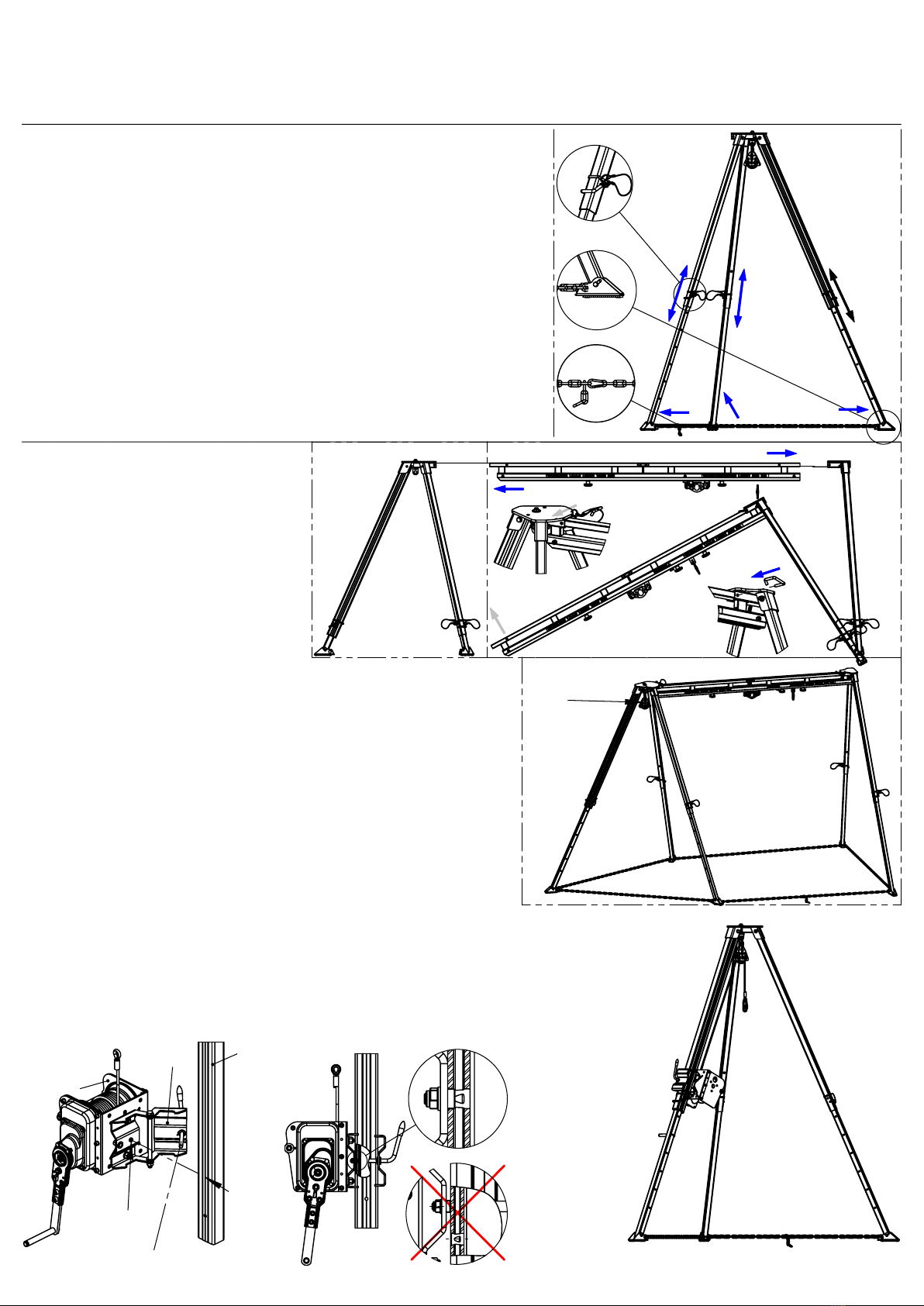
+ in tripods - legs, safety pins, eye bolts, feet, chain, connecting elements.
- after every 12 months of utilization, personal protective equipment must be withdrawn from use to carry out periodical detailed inspection. The periodic
inspection must be carried out bu a competent person for periodic inspection. The periodic inspection can be carried out also by the manufacturer or his
authorized representative. In case of some types of the complex equipment e.g. some types of retractable fall arresters the annual inspection can be
carried out only by the manufacturer or his authorized representative.
- regular periodic inspections ore the essential for equipment maintenance and the safety of the users which depends upon the continued efficiency and
durability of the equipment.
- during periodic inspection it is necessary to check the legibility of the equipment marking.
- it is essential fo the safety of the user that if the product is re-sold outside the original country of destination the reseller shall provide instruction for use, for
maintenance, for periodic examination and for repair in language of the country in which the product is to be sold.
- personal protective equipment must be withdrawn from use immediately when any doubt arise about its condition for safe use and not used again until
confirmed in writing by equipment manufacturer or his representative after carried out the detailed inspection.
- a full body harness (conforming EN 361) is the only acceptable body holding device that can be used in a fall arrest system.
- in full body harness use only attaching points marked with big letter "A" to attach a fall arrest system.
- the anchor device or anchor point fo the fall arrest system should always be positioned, and the work carried out in such a way, as to minimise both the
potential for falls and potential fall distance. The anchor device/point should be placed above the position of the user. The shape and construction of the
anchor device/point shall not allowed to self-acting disconnection of the equipment. Minimal static strength of the anchor device/point is 10 kN. It is
recommended to use certified and marked structural anchor point complied with EN795.
- it is obligatory to verify the free space required beneath the user at the workplace before each occasion of use the fall arrest system, so that, in the case
of a fall, there will be no collision with the ground or other obstacle in the fall path. The required value of the free space should be taken from instruction
manual of used equipment.
- there are many hazards that may affect the performance of the equipment and corresponding safety precautions that have to be observed during
equipment utilization, especially:
+ trailing or looping of lanyards or lifelines over sharp edges, + any defects like cutting, abrasion, corrosion, + climatic exposure, + pendulum falls, +
extremes of temperature, + chemical reagents, + electrical conductivity.
- personal protective equipment must be transported in the package (e.g.: bag made of moisture-proof textile or foil bag or cases made of steel or
plastic) to protect in against damage or moisture.
- the equipment can be cleaned without causing adverse effect on the materials in the manufacture of the equipment. For textile products use mild
detergents for delicate fabrics, wash by hand or in a machine and rinse in water. Plastic parts can be cleaned only with water. When the equipment
becomes wet, either from being in use or when due cleaning, it shall be allowed to dry naturally, and shall be kept away from direct heat. In metallic
products some mechanic parts (spring, pin, hinge, tec.) can be regularly slightly lubricated to ensure better operation. Other maintenance and cleaning
procedures should be adhered to detailed instructions staed in the manual of the equipment.
- personal protective equipment should be stored loosely packed, in a well-ventilated place, protected from direct light, ultraviolet degradation, damp
environment, sharp edges, extreme temperatures and corrosive or aggressive substances.
WITHDRAWAL FROM USE AFTER ARRESTING A FALL
- Safety tripod TM12 must be withdrawn from use immediately when it have benn used to arrest a fall. After that must be carried out detailed
manufacturer's inspection of the tripod. The manufacturer's inspection can be carried out by: manufacturer or person recommended by manufacturer or
company recommended by manufacturer. During this inspection will be established if the tripod can be longer used and will be defined the admissible
time of tripod use till next manufacturer's inspection.
ADMISSIBLE TIME OF USE
- The tripod can be used for 5 years counting from a date of putting the tripod into operation. After this period the tripod must be withdrawn from use to
carry out manufacturer's detailed inspection. The manufacturer inspection can be carried out by: manufacturer or person recommended by
manufacturer or company recommended by manufacturer. Dudring this inspection will be established admissible time of period use till next
manufacturer's inspection.
Page 4 of 4
IDENTITY CARD
Device
name
Reference
number
User
name
Date of
manufacture
Serial
number
Date of
installation
PERIODIC EXAMINATION AND REPAIR HISTORY
Date
of
insp.
Type of inspection
(periodical/special/...)
Result
Next
inspection
date
Signature of
the person
responsible
edition: 4/29.05.2012
TM
CanaSafe www.canasafe.com
info@canasafe.com
Table of contents
Popular Camera Accessories manuals by other brands

Ego Power+
Ego Power+ BA1400T Operator's manual

The PiHut
The PiHut ZeroView User guide and information

Axis
Axis T8133 Midspan 30W installation guide

Delta Membranes
Delta Membranes PowerMaxx2 Installation & operating manual

Slide Kamera
Slide Kamera HST-3 user manual

Nicopure Labs
Nicopure Labs Reactor user manual