3M DBI-SALA 8000140 User manual

© 3M 2023
USER INSTRUCTIONS
5908150 Rev. A
3M™ DBI-SALA®
TRIPOD
;For identication of product codes, refer to Table 1. See “Table 1 - Product Specications” for more product information.
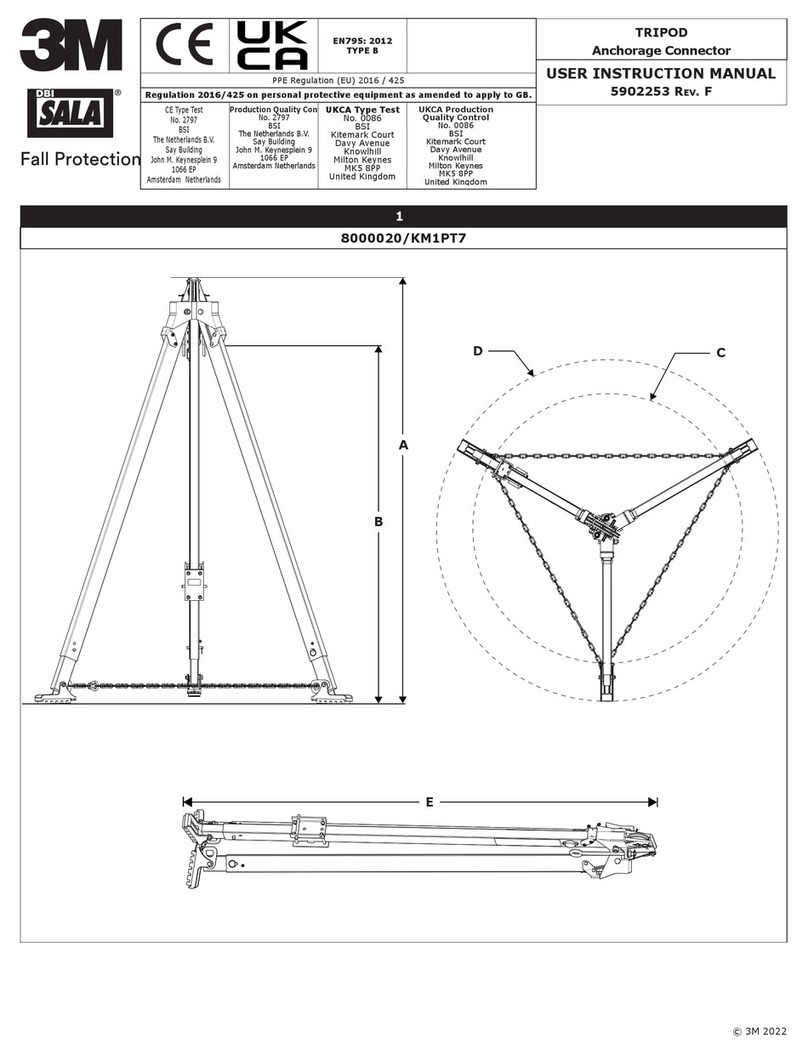
Figure 1 - Product Overview
Model D1 D2 D3 Weight
8000140 68 in. (172.7 cm) at lowest position;
93 in. (236.2 cm) at highest position 70 in. (177.8 cm) 58 in. - 77 in.
(147.3 cm - 195.6 cm) 47 lb. (21 kg)
8000141 96 in. (243.8 cm) at lowest position;
118 in. (299.7 cm) at highest position 102 in. (259 cm) 79 in. - 96 in.
(200.7 cm - 243.8 cm) 56 lb. (25 kg)
D1
D2
D3
OSHA 29 CFR 1910.140
OSHA 29 CFR 1926.502

FORM NO: 5908277 REV: B 2
SAFETY INFORMATION
Please read, understand, and follow all safety information contained in these instructions, prior to the use of this product. FAILURE TO DO SO
COULD RESULT IN SERIOUS INJURY OR DEATH.
These instructions must be provided to the user of the equipment. Retain these instructions for future reference.
Intended Use:
This product is used as part of a complete Fall Protection system.
Use in any other application including, but not limited to, non-approved material handling, recreational or sports-related activities, or other activities not
described in these instructions, is not approved by 3M and could result in serious injury or death.
This product is only to be used by trained users in workplace applications.
!WARNING
This product is used as part of a complete Fall Protection system. All users must be fully trained in the safe installation and operation of their complete Fall
Protection system. Misuse of this product could result in serious injury or death. For proper selection, operation, installation, maintenance, and service,
refer to all instruction manuals and manufacturer recommendations. For more information, see your supervisor or contact 3M Technical Services.
• To reduce the risks associated with using a Conned Space Entry-Rescue System which, if not avoided, could result in serious injury or
death:
- Inspect the product before each use and after any fall event, in accordance with the procedures specied in these instructions.
- If inspection reveals an unsafe or defective condition, remove the product from service immediately and clearly tag it “DO NOT USE”. Destroy or
repair the product as required by these instructions.
- Any product that has been subject to fall arrest or impact force must be immediately removed from service. Destroy or repair the product as
required by these instructions.
- Ensure that Fall Protection systems assembled from components made by dierent manufacturers are compatible and meet all applicable Fall
Protection regulations, standards, or requirements. Always consult a Competent or Qualied Person before using these systems.
- The product must only be installed as described in its instruction manuals. Installations and use outside the scope of these instruction manuals must
be approved in writing by 3M.
- Only connect Fall Protection subsystems to the designated anchorage connection points on the product.
- Before installing, ensure that the installation methods and the product will not interfere with electric lines, gas lines, or other critical materials or
systems.
- Ensure the product is congured and installed properly for safe operation as described in these instructions.
- Do not exceed the number of allowable users specied in these instructions.
- Do not twist, tie, knot, or allow slack in the lifeline.
- Do not connect to the system while it is being transported or installed.
- Use caution when installing, using, or moving the product as moving parts may create pinch points.
- Lockout/tagout procedures must be followed when applicable.
- Ensure the lifeline of your connecting subsystem does not extend outside the legs of the tripod.
- Never use the tripod without the leg chains secured.
• To reduce the risks associated with working at height which, if not avoided, could result in serious injury or death:
- Your health and physical condition must allow you to safely work at height and to withstand all forces associated with a fall arrest event. Consult
your doctor if you have questions regarding your ability to use this equipment.
- Never exceed allowable capacity of your Fall Protection equipment.
- Never exceed the maximum free fall distance specied for your Fall Protection equipment.
- Do not use any Fall Protection equipment that fails inspection, or if you have concerns about the use or suitability of the equipment. Contact 3M
Technical Services with any questions.
- Some subsystem and component combinations may interfere with the operation of this equipment. Only use compatible connections. Contact 3M
Technical Services before using this equipment in combination with components or subsystems other than those described in these instructions.
- Use extra precautions when working around moving machinery, electrical hazards, extreme temperatures, chemical hazards, explosive or toxic
gases, sharp edges, abrasive surfaces, or below overhead materials that could fall onto you or your Fall Protection equipment.
- Ensure use of your product is rated for the hazards present in your work environment.
- Ensure there is sucient fall clearance when working at height.
- Never modify or alter your Fall Protection equipment. Only 3M, or persons authorized in writing by 3M, may make repairs to 3M equipment.
- Before using Fall Protection equipment, ensure a written rescue plan is in place to provide prompt rescue if a fall incident occurs.
- If a fall incident occurs, immediately seek medical attention for the fallen worker.
- Only use a full body harness for Fall Arrest applications. Do not use a body belt.
- Minimize swing falls by working as directly below the anchorage point as possible.
- A secondary Fall Protection system must be used when training with this product. Trainees must not be exposed to an unintended fall hazard.
- Always wear appropriate Personal Protective Equipment when installing, using, or inspecting the product.
- Never work below a suspended load or worker.
- Always maintain 100% tie-o.
ENEN

3
;Always ensure you are using the latest revision of your 3M instruction manual. Visit www.3m.com/userinstructions or
contact 3M Technical Services for updated instruction manuals.
PRODUCT OVERVIEW:
Figure 1 identies available product models. Tripods are adjustable systems that may secure connecting subsystems in various
congurations for use in conned space applications. This product may be used in Fall Arrest, Rescue, and Work Positioning
applications.
Figure 2 identies key components of the available product models. The Head Mount Pulley (A) routes the lifeline of the user’s
primary subsystem, which is secured by a pin atop the pulley. Below the tripod head, the Eye Bolt (B) may also be used to
secure a connecting subsystem. The Leg Lock (C) secures the Tripod Leg (D) in place during use. The length may be adjusted
and secured with use of each leg’s Adjustment Pin (E). The Tripod Foot (F) levels the tripod and routes the Tripod Chain (G),
which secures the tripod legs. The Mounting Bracket (H) receives a connecting subsystem for routing through the tripod pulleys.
There are a number of accessories that may be used with this product. Additional Mounting Brackets (8005048) may be
purchased for securing connecting subsystems to the tripod. The Leg Mount Pulley (8003238) attaches to a tripod leg and may
be used to route an additional lifeline. The Snatch Block Pulley (8003205) is secured to the eye bolt and is an additional means
of routing a lifeline. All accessories are sold separately.
See Table 1 for more information on Component Specications.
Figure 2 - Components
A
B
C
F
G
H
E
D
8003205 8003238 8005048

4
;Before using this equipment, record the product identication information from the ID label in the ‘Inspection and
Maintenance Log’ at the back of this manual.
Table 1 – Product Specications
System Specications:
User Capacity: The user capacity of this system is determined by its maximum static strength. See Section 4 for
more information.
Material Handling: This product may be used for material handling as described in these instructions. See Section 4 for
more information.
Standards: Each product model is certied to, or conforms with, the applicable standards and regulations listed
within Figure 1. If none are specied, then all standards and regulations listed on the cover apply.
Component Specications:
Figure 2
Reference Component Materials
A Head Mount Pulley Zinc-plated steel
B Eye Bolt Zinc-plated steel
C Leg Lock Zinc-plated steel
D Tripod Leg Aluminum
E Adjustment Pin Zinc-plated steel
FTripod Foot Aluminum, rubber
G Tripod Chain Zinc-plated steel
HMounting Bracket Zinc-plated steel
Accessories:
Model
Number Component Materials
8003205 Snatch Block Pulley Zinc-plated steel
8003238 Leg Mount Pulley Zinc-plated steel, nylon plastic
8005048 Mounting Bracket Zinc-plated steel

5
1.0 PRODUCT APPLICATION
1.1 PURPOSE: Conned space systems are products designed for use in work areas with limited room or maneuverability.
System applications vary with the product. For more information on system applications, refer to the “Product Overview”
and Table 1.
1.2 SUPERVISION: Use of this equipment must be supervised by a Competent Person. Installation must be supervised by a
Qualied Person.
1.3 STANDARDS: Your product conforms to the national or regional standards identied on the front cover of these
instructions. If this product is resold outside the original country of destination, the re-seller must provide these
instructions in the language of the country in which the product will be used.
;For more information on certication or conformance requirements, refer to the applicable standards and
regulations listed for your product (e.g. the ANSI/ASSP Z359 Fall Protection codes).
1.4 TRAINING: This equipment must be installed and used by persons trained in its correct application. These instructions are to be used
as part of an employee training program as required by national, regional, or local standards. It is the responsibility of the users and
installers of this equipment to ensure they are familiar with these instructions, trained in the correct care and use of this equipment,
and are aware of the operating characteristics, application limitations, and consequences of improper use of this equipment.
1.5 RESCUE PLAN: When using this equipment and connecting subsystems, the employer must have a written rescue plan and
the means to implement and communicate that plan to users, authorized persons, and rescuers. A trained, on-site rescue team
is recommended. Team members should be provided with the equipment and techniques necessary to perform a successful
rescue. Training should be provided on a periodic basis to ensure rescuer prociency. Rescuers should be provided with these
instructions. There should be visual contact or means of communication with the person being rescued at all times during the
rescue process.
2.0 SYSTEM REQUIREMENTS
2.1 ANCHORAGE: The anchorage structure securing this product must be able to withstand any required loads as permitted by its
Fall Protection system. See Section 4 for more information.
2.2 CAPACITY: The user capacity of a complete Fall Protection system is limited by its lowest rated maximum capacity component.
For example, if your connecting subsystem has a capacity that is less than your harness, you must comply with the capacity
requirements of your connecting subsystem. See the manufacturer instructions for each component of your system for capacity
requirements.
2.3 ENVIRONMENTAL HAZARDS: Use of this equipment in areas with environmental hazards may require additional
precautions to prevent injury to the user or damage to the equipment. Hazards may include, but are not limited to: high
heat, chemicals, corrosive environments, high voltage power lines, explosive or toxic gases, moving machinery, sharp
edges, or overhead materials that may fall and contact the user or equipment. Contact 3M Technical Services for further
clarication.
2.4 LIFELINE HAZARDS: Ensure the lifeline is kept free from all hazards including, but not limited to: entanglement with
users, other workers, moving machinery, other surrounding objects, or impact from overhead objects that could fall onto
the lifeline or users.
2.5 COMPONENT COMPATIBILITY: 3M equipment is designed for use with 3M equipment. Use with non-3M equipment
must be approved by a Competent Person. Substitutions made with non-approved equipment may jeopardize equipment
compatibility and may aect the safety and reliability of your Fall Protection system. Read and follow all instructions and
warnings for all equipment prior to use.
2.6 CONNECTOR COMPATIBILITY: Connectors are compatible with connecting elements when the size and shape of either
component does not cause the connector to inadvertently open, regardless of orientation. Connectors must comply with
applicable standards. Connectors must be fully closed and locked during use.
3M Connectors (snap hooks and carabiners) are designed to be used only as specied in each instruction manual. Ensure
connectors are compatible with the system components to which they are connected. Do not use equipment that is non-
compatible. Use of non-compatible components may cause the connector to unintentionally disengage (see Figure 3). If
the connecting element to which a connector attaches is undersized or irregular in shape, a situation could occur where
the connecting element applies a force to the gate of the connector (A). This force could then cause the gate to open (B),
disengaging the connector from the connecting element (C).

6
2.7 MAKING CONNECTIONS: All connections must be compatible in size, shape, and strength. See Figure 4 for examples of
inappropriate connections. Do not attach snap hooks and carabiners:
A. To a D-Ring to which another connector is attached.
B. In a manner that would result in a load on the gate. Large-throat snap hooks should not be connected to D-Rings or
other connecting elements, unless the snap hook has a gate strength of 16 kN (3,600 lbf) or greater.
C. In a false engagement, where size or shape of the connector or connecting element is not compatible and, without
visual conrmation, would seem to be fully engaged.
D. To each other.
E. Directly to harness webbing, lanyard leg material, or tie-back material unless such a connection is explicitly allowed
for by the manufacturer instructions.
F. To any object whose size or shape does not allow the connector to fully close and lock, or that could cause connector
roll-out.
G. In a manner that does not allow the connector to align properly while under load.
Figure 3 - Connector Compatibility Figure 4 - Making Connections
A. B. C. D.
E. F. G.
A B C

7
3.0 INSTALLATION
3.1 OVERVIEW: Conned space systems must be installed as described in their manufacturer instructions. All system
requirements must be met as described. Eective planning and awareness of your worksite and your equipment are of
great help in making this process move as smoothly as possible.
3.2 PLANNING: Plan your Fall Protection system before starting your work. Account for all factors that may aect your safety
before, during, and after a fall. Consider all requirements and limitations specied in these instructions.
A. SHARP EDGES: Avoid working where system components may be in contact with, or scrape against, unprotected
sharp edges and abrasive surfaces. All sharp edges and abrasive surfaces should be covered with protective material.
B. NUMBER OF USERS: The number of users that may secure to this product is limited by the weight of those users
and the maximum static load that can be expected with their use of the product. The maximum static load expected
through use of this product must always be equal to or less than its maximum static strength. See Section 4 for more
information about user capacity.
;The number of users may also be limited by product design.
C. COMPATIBILITY: When installing your system, it is important that you use compatible components. Each product
model is compatible for use with a specic set of product models or designs.
Self-Retracting Devices
(SRDs) The maximum arresting force for connecting subsystems must meet the requirements
listed in Section 4.
Winches Use must not exceed the lifting capacity of the winch.
D. SECONDARY SYSTEMS: When using this product for Work Positioning applications, a secondary or backup Fall
Arrest system is recommended and may be required by some standards.
E. DIMENSIONS AND WORKING AREA: Before installing the tripod, the user should conrm that their working area
will t the tripod. The tripod feet must be planted rmly on the working surface, outside the hole or opening where
users will be raised or lowered.
Model Number Opening Diameter (A)
8000140 23 in. - 32 in. (58.4 cm - 81.3 cm)
8000141 33 in. - 44 in. (83.8 cm - 111.7 cm)
Figure 5 - Working Area
A
A
3.3 INSTALLING THE TRIPOD: See Figure 6 for reference. To install the tripod:
1. Prepare the tripod. Lay the tripod at on the ground and adjust each leg to the proper height. Use the adjustment
pins to set each leg at its selected position.
2. Spread the tripod legs. Position the tripod upright and spread each tripod leg. Pull the leg out to release its spring,
then set the leg at its full width. Once set, release the leg to re-engage the spring and secure the leg lock.
3. Position the tripod. Place the tripod over the opening so that the lifeline of any secured connecting subsystem will
be routed through the center of the opening. Level the tripod by adjusting the height of the tripod legs.
4. Secure the tripod chain. Route the tripod chain through the rings at the bottom of each tripod leg. Adjust the
length of the tripod chain to match the spread of the tripod legs, then secure the chain with its connector.
5. Complete nal system setup. Before using the tripod, secure any additional equipment and connecting subsystems
as necessary for your conguration.
A. Connect any additional equipment. This includes any additional pulleys or brackets that may be needed for
your connecting subsystem. See “Connecting Additional Equipment” for more information.
B. Secure any connecting subsystems. Connecting subsystems may be secured to the Eye Bolt (A) or to a
Mounting Bracket (B) installed on a tripod leg. Route the subsystem lifeline through one of the tripod pulleys.
See “Securing Connecting Subsystems” for more information.

8
Figure 6 - Installing the Tripod
12345
A
B
3.4 CONNECTING ADDITIONAL EQUIPMENT: Additional equipment may be necessary depending on your system’s
conguration.
A. MOUNTING BRACKETS: Mounting brackets are used to secure a winch or Self-Retracting Device (SRD) to the
tripod. To install a mounting bracket, position the bracket at the desired location on a tripod leg, then secure with the
provided fasteners. Tighten fasteners to 15 ft-lb. (20.3 N-m). See Figure 7 for reference.
;Never install mounting brackets onto the telescoping portion of the tripod legs.
Figure 7 - Connecting Mounting Brackets
B. PULLEYS: The user’s primary subsystem should route through the built-in head mount pulleys. Additional pulleys
may be installed when additional connecting subsystems are used. See Figure 8 for reference.
;All tripod pulleys can accommodate lifelines with diameters up to 1/4 in. (6 mm).
1. Leg Mount Pulley: The leg mount pulley is secured to one of the tripod legs. Position the leg mount pulley
within 12 in. (30.5 cm) of the leg lock. Secure the pulley to the tripod leg using the provided fasteners. Tighten
fasteners to 15 ft-lb. (20.3 N-m).
;It may be necessary to remove one of the tripod’s eye bolts to gain clearance for the lifeline.
2. Snatch Block Pulley: The snatch block pulley is secured to one of the eye bolts. Secure the pulley to the eye
bolt using the provided pin.
;Never route winch lifelines through the snatch block pulley.
Figure 8 - Connecting Additional Pulleys
8.1 8.2
<12 in.
(30.5 cm)

9
3.5 SECURING CONNECTING SUBSYSTEMS: Connecting subsystems may be secured to one of the tripod’s eye bolts or
onto a mounting bracket. See Figure 9 for reference. To secure a connecting subsystem:
;This product may have a total of four connecting subsystems secured at any given time. This includes two primary
subsystems and two secondary subsystems.
;See “Planning” for more information on connecting subsystem compatibility.
A. EYE BOLTS: Secure the connecting subsystem to the eye bolt using the connector atop the connecting subsystem.
Alternatively, a clevis pin may be used.
B. MOUNTING BRACKETS: Place the connecting subsystem’s bracket onto the mounting bracket, aligning the holes
in the two brackets. Secure the brackets by threading the locking pin on the subsystem bracket through the aligned
bracket holes. Thread the lifeline of the connecting subsystem through one of the tripod pulleys.
;It is recommended that you thread your primary subsystem’s lifeline through the head mount pulleys.
;Never secure two connecting subsystems to the same tripod leg.
Figure 9 - Securing Connecting Subsystems
4.0 USE
4.1 BEFORE EACH USE: Verify that your work area and Fall Protection system meet all criteria dened in these instructions.
Verify that a formal Rescue Plan is in place. Inspect the product per the ‘User’ inspection points dened in the “Inspection
and Maintenance Log”. If inspection reveals an unsafe or defective condition, or if there is any doubt about its condition
for safe use, remove the product from service immediately. Clearly tag the product “DO NOT USE”. See Section 5 for more
information.
4.2 ANCHORAGE: In addition to product capacity, any fall protection system must take into account the strengths of any
supporting structures or components.
A. ANCHORAGE STRUCTURE: The anchorage structure securing this product must be able to withstand the required
loads, as permitted by this product’s fall protection system.
Static Load 5,000 lbf (22.2 kN)
B. ANCHORAGE CONNECTION POINTS: Anchorage connection points used with the product must be able to
withstand any loads applied by the product.

10
4.3 USER CAPACITY: The user capacity of this product is determined by its maximum static strength. Maximum static
strength is dened by the applicable standard or regulation and states the maximum static load that the product can
withstand. The maximum static load for your system must always be equal to or less than the product’s maximum static
strength.
;When using this product, you may use one of the example congurations provided, or you may design your own
conguration using the described methods.
;Maximum arresting force is limited by the user’s connecting subsystem.
A. USER CAPACITY - OSHA
To calculate your maximum static load, double the maximum arresting force of your connecting subsystem and add
twice the weight of any additional users beyond the rst.
;OSHA static load and static strength values as tested include a 2:1 safety factor.
Maximum Static Strength 5,000 lbf (22.2 kN)
Primary Subsystem Location Maximum Arresting Force
Eye Bolt (A) 1,800 lbf (8 kN)
Mounting Bracket (B) 1,500 lbf (6.7 kN)
See Figure 10 for reference. Each user’s primary subsystem must have a maximum arresting force less than or equal
to the limit for its mounting point, whether it is an eye bolt or mounting bracket.
The following example congurations may be used in compliance with these regulations.
Maximum Arresting Force: 1,350 lbf (6 kN)
Number of
Users Maximum
User Weight Maximum
Static Load
Primary Subsystem Location
User 1 User 2
1 user Not applicable 2,700 lbf (12 kN) A or B ---
2 users 420 lb. (191 kg) 3,540 lbf (15.8 kN) A or B A or B
Maximum Arresting Force: 1,500 lbf (7 kN)
Number of
Users Maximum User Weight Maximum Static Load Primary Subsystem Location
User 1 User 2
1 user Not applicable 3,000 lbf (13.3 kN) A or B ---
2 users 420 lb. (191 kg) 3,540 lbf (15.7 kN) A or B A or B
Maximum Arresting Force: 1,800 lbf (8 kN)
Number of
Users Maximum User Weight Maximum Static Load Primary Subsystem Location
User 1 User 2
1 user Not applicable 3,600 lbf (16.0 kN) A ---
2 users 420 lb. (191 kg) 4,440 lbf (18.7 kN) A B (≤1,500 Maximum
Arresting Force)
Figure 10 - Tripod Mounting Locations
A
B

11
4.4 TWO-PERSON USE: The tripod may be used by two persons as long as one person remains grounded while the other is
raised or lowered. Each person must be secured to their own connecting subsystem.
;In a conguration with four subsystems, each user might have a winch secured to their sternal D-ring for
positioning, with a connecting subsystem secured to their dorsal D-ring for fall arrest.
4.5 MATERIAL HANDLING: This product may be used for material handling. To use in material handling:
;Before securing your material load, verify that it has been prepared for transport.
;Never secure this product to materials and users simultaneously.
;Product used for material handling must be inspected by a Competent Person before its next use.
1. Secure a connecting subsystem. The connecting subsystem may be secured to the eye bolt or to a mounting
bracket. Material capacity is listed for each location.
2. Route the subsystem lifeline through the tripod head. Secure the lifeline within the head mount pulley using
the head mount pin.
3. Secure the lifeline to your material load. Lower or raise the material load as necessary.
;Material capacity values include a 5:1 safety factor.
Mounting Location Material Capacity
Eye Bolt 1,000 lb. (454 kg)
Mounting Bracket 620 lb. (281 kg)
4.6 AFTER A FALL: If this equipment is subjected to fall arrest or impact force, remove it from service immediately. Clearly
tag it “DO NOT USE”. See Section 5 for more information.
5.0 INSPECTION
;After equipment has been removed from service, it may not be returned to service until a Competent Person conrms in
writing that it is acceptable to do so.
5.1 INSPECTION FREQUENCY: The product shall be inspected before each use by a user and, additionally, by a Competent
Person other than the user at intervals of no longer than one year. A higher frequency of equipment use and harsher
conditions may require increasing the frequency of Competent Person inspections. The frequency of these inspections
should be determined by the Competent Person per the specic conditions of the worksite.
5.2 INSPECTION PROCEDURES: Inspect this product per the procedures listed in the “Inspection and Maintenance Log”.
Documentation of each inspection should be maintained by the owner of this equipment. An inspection and maintenance
log should be placed near the product or be otherwise easily accessible to users. It is recommended that the product is
marked with the date of next or last inspection.
5.3 DEFECTS: If the product cannot be returned to service because of an existing defect or unsafe condition, then the
product must be either destroyed or sent to 3M or a 3M-authorized service center for repair.
5.4 PRODUCT LIFE: The functional life of the product is determined by work conditions and maintenance. As long as the
product passes inspection criteria, it may remain in service.
6.0 MAINTENANCE, STORAGE, AND REPAIR
;Equipment that is in need of maintenance or scheduled for maintenance should be tagged “DO NOT USE”. These
equipment tags should not be removed until maintenance is performed.
6.1 CLEANING: Periodically clean the metal components of the product using warm water and a mild soap solution. Rinse
the product with clean water, then allow it to air dry. For more information, please refer to the technical bulletin on our
website: https://www.3M.com/FallProtection/Mechanical-Device-Cleaning
6.2 REPAIR: Only 3M or parties authorized in writing by 3M may make repairs to this equipment.
6.3 STORAGE AND TRANSPORT: Store and transport the product in a cool, dry, clean environment out of direct sunlight.
Avoid areas where chemical vapors may exist. Thoroughly inspect components after extended storage.

12
7.0 LABELS and MARKINGS
7.1 SUMMARY: The “Product Labels” gure illustrates labels and markings present on the product. See below for a summary
of information provided with each label and marking.
;Label images are intended to be representative. Please refer to your product labels for specic information.
;Missing or damaged labels must be replaced. All labels must be fully legible.
AConnected Safety ID Label
BTighten all fasteners to value shown.
C1) User capacity - See user instructions.
2) Applicable standards
D1) Manufactured (Year/month) 2) Model number 3) Serial number
EHazard Label
8.0 RFID Tag
8.1 LOCATION: 3M product covered in these user instructions is equipped with a Radio Frequency Identication (RFID) Tag.
RFID Tags may be used in coordination with an RFID Tag Scanner for recording product inspection results. See “RFID Tag
Location” for where your RFID Tag is located.
8.2 DISPOSAL: Prior to disposing of this product, remove the RFID Tag and dispose/recycle in accordance with local
regulations. For more information, please visit our website: http://www.3M.com/FallProtection/RFID
9.0 GLOSSARY OF TERMS
9.1 DEFINITIONS: The following terms and denitions are used in these instructions.
;For a comprehensive list of terms and denitions, please visit our website: www.3m.com/FallProtection/ifu-glossary
• AUTHORIZED PERSON: A person assigned by the employer to perform duties at a location where the person will be exposed to a fall
hazard.
• COMPETENT PERSON: One who is capable of identifying existing and predictable hazards in the surroundings or working conditions
which are unsanitary, hazardous, or dangerous to employees, and who has authorization to take prompt corrective measures to
eliminate them.
• FALL ARREST SYSTEM: A collection of Fall Protection equipment congured to protect the user in the event of a fall.
• QUALIFIED PERSON: A person with a recognized degree, certicate, or professional standing, or who by extensive knowledge,
training, and experience has successfully demonstrated their ability to solve or resolve problems relating to Fall Protection and Rescue
systems to the extent required by applicable national, regional, and local regulations.
• RESCUE SYSTEM: A collection of Fall Protection equipment congured to remove a person from hazards to a safe location. No free fall is
permitted.
• RESCUER: A person using the Rescue system to perform an assisted rescue.
• RESTRAINT SYSTEM: A collection of Fall Protection equipment congured to prevent the user from reaching a fall hazard. No free fall is
permitted.
• USER: A person who performs activities while protected by a Fall Protection system.
• WORK POSITIONING SYSTEM: A collection of Fall Protection equipment congured to support a user at a work position.

13
Figure 11 - RFID Tag Location
A
A
Figure 12 - Product Labels
9502313 Rev. D
≤ 15 ft-lbs.
(20.3 N*m)
9503052 REV. G
OSHA 29 CFR 1910.140
OSHA 29 CFR 1926.502
9516334 Rev. A
X 2
MAX
A
B
C
D
E
E
E
A B C
D
E
12
3
1
2
B
B

Table 2 – Inspection and Maintenance Log
Model Number (Serial Number):
Date Purchased: Date of First Use:
···
;This product must be inspected by the user before each use. Additionally, a Competent Person other than the user must
inspect this equipment at least once each year.
···
Component Inspection Procedure Inspection Result
Pass Fail
Product or System
(Figure 2)
Inspect the entire system for damage, deformation, corrosion, and rust.
Look for cracks, bends, dents, or wear that could aect strength and
operation of the system.
Verify that each tripod leg can be smoothly extended and retracted.
Conrm that the legs are straight and that each locks into place when the
tripod is standing.
Verify that each tripod foot can pivot when adjusted and that each rests in
place when the tripod is standing.
Inspect the tripod chain. Ensure that the chain is free of defects and can be
properly secured and adjusted.
Inspect the tripod head and pulleys. Ensure the pulleys are clean and able
to rotate freely.
Verify that all adjustment points (pins, bolts, tri-screws, adjusting screws,
etc.) are in full functional condition and are properly adjusted.
Labels (Figure 12) All labels are present and fully legible.
Fall Protection Equipment Additional Fall Protection equipment that is used with the product is
installed and inspected per the manufacturer instructions.
···
;If the product fails an inspection procedure, then the product fails overall inspection. If the product fails inspection, remove
it from service immediately. Clearly tag the product “DO NOT USE”. See Section 5 for more information.
···
Inspection Type:
User
Competent Person Overall Inspection Result:
Pass
Fail
Inspected By: Date of Inspection:
Signature: Next Inspection Due:
···
Additional Notes:

© 3M 2023
INSTRUCTIONS D’UTILISATION
5908150 Rév. A
TRÉPIED
3M™DBI-SALA®
;Pour trouver les codes de produit, consultez le tableau 1. Consultez le « Tableau 1 – Spécications du produit » pour obtenir
plus d’informations sur le produit.
Figure 1 – Présentation du produit
Modèle D1 D2 D3 Poids
8000140 68 po (172,7 cm) à la position
la plus basse; 93 po (236,2 cm)
à la position la plus élevée 70 po (177,8 cm) 58 po - 77 po
(147,3 cm - 195,6 cm) 47 lb (21 kg)
8000141 96 po (243,8 cm) à la position
la plus basse; 118 po (299,7 cm)
à la position la plus élevée 102 po (259 cm) 79 po - 96 po
(200,7 cm - 243,8 cm) 56 lb. (25 kg)
D1
D2
D3
OSHA 29 CFR 1910.140
OSHA 29 CFR 1926.502

NUMÉRO DU FORMULAIRE : 5908277
RÉV. : B 16
CONSIGNES DE SÉCURITÉ
Veuillez lire, comprendre et suivre toutes les informations de sécurité contenues dans ces instructions avant d’utiliser ce produit.
NE PAS LE FAIRE POURRAIT ENTRAÎNER DES BLESSURES GRAVES OU LA MORT.
Ces instructions doivent être fournies à l’utilisateur de l’équipement. Conservez ces instructions pour toute référence ultérieure.
Utilisation prévue :
Ce produit est utilisé dans le cadre d’un système complet de protection contre les chutes.
L’utilisation dans toute autre application, y compris, mais sans s’y limiter, la manutention de matériaux non approuvés, les activités récréatives ou sportives,
ou d’autres activités non décrites dans ces instructions, n’est pas approuvée par 3M et peut entraîner des blessures graves ou la mort.
Ce produit ne doit être utilisé que par des utilisateurs formés dans des applications sur le lieu de travail.
!AVERTISSEMENT
Ce produit est utilisé dans le cadre d’un système complet de protection contre les chutes. Tous les utilisateurs doivent être entièrement formés sur
l’installation et l’utilisation en toute sécurité de leur système de protection contre les chutes complet. Une mauvaise utilisation de ce produit peut
entraîner des blessures graves ou la mort. Pour une sélection, un fonctionnement, une installation, une maintenance et un entretien appropriés,
consultez tous les manuels d’instructions et les recommandations du fabricant. Pour obtenir plus d’informations, consultez votre superviseur ou
communiquez avec les services techniques de 3M.
• Pour réduire les risques associés à l’utilisation d’un système d’entrée et de sauvetage dans un espace clos qui, s’ils ne sont pas évités,
pourraient entraîner des blessures graves ou la mort :
- Inspectez le produit avant chaque utilisation et après toute chute, conformément aux procédures décrites dans ces instructions.
- Si l’inspection révèle une condition dangereuse ou défectueuse, mettez immédiatement le produit hors service et étiquetez-le clairement avec
la mention « NE PAS UTILISER ». Détruisez ou réparez le produit conformément à ces instructions.
- Tout produit qui a subi un arrêt de chute ou une force d’impact doit être immédiatement mis hors service. Détruisez ou réparez le produit
conformément à ces instructions.
- Assurez-vous que les systèmes de protection contre les chutes assemblés à partir de composants fabriqués par diérents fabricants sont compatibles
et respectent tous les règlements, normes ou exigences applicables en matière de protection contre les chutes. Consultez toujours une personne
compétente ou qualiée avant d’utiliser ces systèmes.
- Le produit doit être installé uniquement comme décrit dans ses manuels d’instructions. Les installations et l’utilisation en dehors du cadre de ces
manuels d’instructions doivent être approuvées par écrit par 3M.
- Connectez seulement les sous-systèmes de protection contre les chutes aux points de connexion d’ancrage désignés sur le produit.
- Avant l’installation, assurez-vous que les méthodes d’installation et le produit n’interféreront pas avec des lignes électriques, des conduites de gaz
ou d’autres matériaux ou systèmes critiques.
- Assurez-vous que le produit est conguré et installé correctement pour un fonctionnement en toute sécurité, comme décrit dans ces instructions.
- Ne dépassez pas le nombre d’utilisateurs permis indiqué dans ces instructions.
- Ne tordez pas, n’attachez pas, ne nouez pas et ne laissez aucun jeu dans le câble de sûreté.
- Ne vous raccordez pas au système pendant son transport ou son installation.
- Faites preuve de prudence lors de l’installation, de l’utilisation ou du déplacement du produit, car les pièces mobiles peuvent présenter des risques
de pincement.
- Les procédures de verrouillage/d’étiquetage doivent être respectées, le cas échéant.
- Vériez que la ligne de vie de votre sous-système de raccordement ne dépasse pas les branches du trépied.
- N’utilisez jamais le trépied sans avoir au préalable attaché les chaînes des pieds.
• Pour réduire les risques associés au travail en hauteur qui, s’ils ne sont pas évités, peuvent entraîner des blessures graves ou la mort :
- Votre santé et votre condition physique doivent vous permettre de travailler en hauteur en toute sécurité et de résister à toutes les forces
associées à un arrêt de chute. Consultez votre médecin si vous avez des questions concernant votre capacité à utiliser cet équipement.
- Ne dépassez jamais la capacité autorisée de votre équipement de protection contre les chutes.
- Ne dépassez jamais la distance de chute libre maximale déterminée pour votre équipement de protection contre les chutes.
- N’utilisez pas d’équipement de protection contre les chutes si son inspection échoue, ou si vous avez des inquiétudes quant à l’utilisation ou
à l’adéquation de l’équipement. Communiquez avec les services techniques de 3M si vous avez des questions.
- Certaines combinaisons de sous-systèmes et de composants peuvent nuire au fonctionnement de cet équipement. Utilisez uniquement des
raccords compatibles. Communiquez avec les services techniques de 3M avant d’utiliser cet équipement en combinaison avec des composants
ou des sous-systèmes autres que ceux mentionnés dans ces instructions.
- Prenez des précautions supplémentaires lorsque vous travaillez à proximité de machines en mouvement, de risques électriques, de températures
extrêmes, de risques chimiques, de gaz explosifs ou toxiques, d’arêtes vives, de surfaces abrasives ou sous des matériaux suspendus qui pourraient
tomber sur vous ou sur votre équipement de protection contre les chutes.
- Assurez-vous que l’utilisation de votre produit est adaptée aux dangers présents dans votre environnement de travail.
- Assurez-vous que la distance de chute requise est susante lorsque vous travaillez en hauteur.
- Ne modiez jamais votre équipement de protection contre les chutes. Seules 3M ou les personnes autorisées par écrit par 3M peuvent eectuer
des réparations pour l’équipement de 3M.
- Avant d’utiliser l’équipement de protection contre les chutes, assurez-vous qu’un plan de sauvetage écrit est en place pour être en mesure de
procéder à un sauvetage rapide en cas de chute.
- Si une chute se produit, consultez immédiatement un médecin pour le travailleur qui a chuté.
- Utilisez uniquement un harnais complet pour les applications antichute. N’utilisez pas de ceinture de travail.
- Réduisez au minimum les chutes avec balancement en travaillant aussi près que possible de l’axe vertical directement sous le point d’ancrage.
- Un système secondaire de protection contre les chutes doit être utilisé lors des formations eectuées avec ce produit. Les personnes en formation
ne doivent pas être exposées à un risque de chute involontaire.
- Portez toujours un équipement de protection individuelle approprié lors de l’installation, de l’utilisation ou de l’inspection du produit.
- Ne travaillez jamais sous une charge ou un travailleur en suspension.
- Soyez toujours complètement attaché.
EN
FR-CA

17
;Assurez-vous de toujours utiliser la version la plus récente de votre manuel d’instructions de 3M. Visitez
www.3m.com/userinstructions ou contactez les services techniques de 3M pour obtenir des manuels d’instructions à jour.
PRÉSENTATION DU PRODUIT :
La Figure 1 présente les modèles de produits oerts. Les trépieds sont des systèmes réglables qui peuvent xer des sous-
systèmes de raccordement dans diverses congurations pour une utilisation dans des espaces connés. Ce produit peut
être utilisé dans des applications d’arrêt de chute, de sauvetage et de positionnement de travail.
La Figure 2 illustre les principaux composants des modèles de produits oerts. La poulie de tête (A) achemine la ligne
de vie du sous-système principal de l’utilisateur, qui est xée par une goupille au sommet de la poulie. Sous la tête du
trépied, le boulon à œil (B) peut également être utilisé pour xer un sous-système de raccordement. Le verrou de branche
(C) maintient la branche du trépied (D) en place pendant l’utilisation. La longueur peut être ajustée et bloquée à l’aide de
la goupille de réglage (E) de chaque pied. Le pied du trépied (F) met à niveau le trépied et achemine la chaîne du trépied
(G), qui xe les branches du trépied. Le support de montage (H) reçoit un sous-système de raccordement pour le passage
à travers les poulies du trépied.
De nombreux accessoires peuvent être utilisés avec ce produit. Vous pouvez acquérir des supports de montage supplémentaires
(8005048) pour xer les sous-systèmes de raccordement au trépied. La poulie de branche (8003238) se xe à une branche de
trépied et peut être utilisée pour acheminer une ligne de vie supplémentaire. La poulie coupée (8003205) est xée au boulon
à œil et ore un moyen supplémentaire d’acheminer une ligne de vie. Tous les accessoires sont vendus séparément.
Consultez le Tableau 1 pour obtenir plus d’informations sur les spécications des composants.
Figure 2 – Composants
A
B
C
F
G
H
E
D
8003205 8003238 8005048

18
;Avant d’utiliser cet équipement, inscrivez les informations d’identication du produit qui se trouvent sur l’étiquette
d’identication dans le « Journal d’inspection et d’entretien » à la n de ce manuel.
Table 1 – Spécications du produit
Spécications du système :
Nombre
d’utilisateurs :
Le nombre d’utilisateurs de ce système est déterminé par sa résistance statique maximale.
Consultez la section 4 pour obtenir plus d’informations.
Manipulation
de matériaux :
Ce produit peut être utilisé pour la manutention de matériaux comme décrit dans ces instructions.
Consultez la section 4 pour obtenir plus d’informations.
Normes : Chaque modèle de produit est certié ou conforme aux normes et règlements applicables
mentionnés à la Figure 1. Si aucun n’est mentionné, tous les règlements et normes indiquées
sur la couverture s’appliquent.
Spécications des composants :
Figure 2
Référence Composant Matériaux
APoulie de tête Acier zingué
BBoulon à œil Acier zingué
C Verrou de pied Acier zingué
D Branche de trépied Aluminium
E Goupille de réglage Acier zingué
F Pied de trépied Aluminium, caoutchouc
G Chaîne de trépied Acier zingué
H Support de montage Acier zingué
Accessoires :
Numéro de
modèle Composant Matériaux
8003205 Poulie coupée Acier zingué
8003238 Poulie de montage de branche Acier zingué, plastique nylon
8005048 Support de montage Acier zingué

19
1.0 APPLICATION DU PRODUIT
1.1 OBJECTIF : Les systèmes pour espaces connés sont conçus pour être utilisés dans des zones de travail où l’espace ou
la manœuvrabilité sont limités. Les applications du système varient selon le produit. Pour obtenir plus d’informations sur
les applications du système, consultez la section « Présentation du produit » et le Tableau 1.
1.2 SUPERVISION : L’utilisation de cet équipement doit être supervisée par une personne qualiée. L’installation doit
être supervisée par une personne qualiée.
1.3 NORMES : Votre produit est conforme aux normes nationales ou régionales mentionnées sur la couverture de
ces instructions. Si ce produit est revendu en dehors du pays de destination d’origine, le revendeur doit fournir
ces instructions dans la langue du pays dans lequel le produit sera utilisé.
;Pour obtenir plus d’informations sur les exigences en matière de certication ou de conformité, consultez les
normes et règlements applicables répertoriés pour votre produit (par exemple, les codes de protection contre les
chutes ANSI/ASSP Z359).
1.4 FORMATION : Cet équipement doit être installé et utilisé par des personnes formées à son application correcte.
Ces instructions doivent être utilisées dans le cadre d’un programme de formation des employés, tel que requis par
les normes nationales, régionales ou locales. Il relève de la responsabilité des utilisateurs et des installateurs de
cet équipement de s’assurer de connaître ces instructions, d’être formés à l’entretien et à l’utilisation corrects de
cet équipement et d’être conscients des caractéristiques de fonctionnement, des limites d’application et des
conséquences d’une mauvaise utilisation de cet équipement.
1.5 PLAN DE SAUVETAGE : Lors de l’utilisation de cet équipement et des sous-systèmes de raccordement, l’employeur
doit disposer d’un plan de sauvetage écrit et des moyens de mettre ce plan en œuvre ainsi que de le communiquer
aux utilisateurs, aux personnes autorisées et aux sauveteurs. Il est recommandé d’avoir une équipe de sauvetage
formée sur place. Les membres de l’équipe doivent disposer de l’équipement et des techniques nécessaires pour
eectuer un sauvetage réussi. Une formation doit être dispensée périodiquement pour assurer la compétence des
sauveteurs. Ces instructions doivent être fournies aux sauveteurs. En tout temps pendant le processus de sauvetage,
un contact visuel ou des moyens de communication doivent être établis avec la personne étant secourue.
2.0 CONFIGURATION REQUISE
2.1 ANCRAGE : La structure d’ancrage de ce produit doit être capable de supporter toutes les charges requises par
le système de protection contre les chutes. Consultez la section 4 pour obtenir plus d’informations.
2.2 CAPACITÉ : La capacité d’utilisation d’un système complet de protection contre les chutes est limitée par le composant
ayant la capacité maximale nominale la moins élevée. Par exemple, si votre sous-système de raccordement a une
capacité inférieure à celle de votre harnais, vous devez vous conformer aux exigences de capacité de votre sous-système
de raccordement. Consultez les instructions du fabricant de chaque composant de votre système pour connaître les
exigences en matière de capacité.
2.3 RISQUES LIÉS À L’ENVIRONNEMENT : L’utilisation de cet équipement dans des zones présentant des risques liés
à l’environnement peut nécessiter des précautions supplémentaires pour éviter de blesser l’utilisateur ou d’endommager
l’équipement. Les dangers peuvent inclure, mais sans s’y limiter : la chaleur élevée, les produits chimiques, les
environnements corrosifs, les lignes électriques à haute tension, les gaz explosifs ou toxiques, les machines en
mouvement, les bords tranchants ou les matériaux suspendus qui peuvent tomber et heurter l’utilisateur ou
l’équipement. Communiquez avec les services techniques de 3M pour obtenir plus de précisions.
2.4 RISQUES LIÉS À LA LIGNE DE VIE : Assurez-vous que le cordon d’assujettissement est exempt de tout danger,
y compris, mais sans s’y limiter : l’enchevêtrement avec des utilisateurs, d’autres travailleurs, des machines en
mouvement ou d’autres objets environnants, ou les objets situés au-dessus qui pourraient heurter le cordon
d’assujettissement ou les utilisateurs en tombant.
2.5 COMPATIBILITÉ DES COMPOSANTS : L’équipement de 3M est conçu pour être utilisé avec l’équipement de 3M.
L’utilisation avec l’équipement d’un autre fabricant que 3M doit être approuvée par une personne qualiée. Utiliser
un équipement non approuvé peut entraîner une incompatibilité entre les équipements et compromettre la sécurité
et la abilité de votre système de protection contre les chutes. Lisez et suivez toutes les instructions et tous les
avertissements pour tous les équipements avant de les utiliser.
2.6 COMPATIBILITÉ DES RACCORDS : Les connecteurs sont compatibles avec les éléments de connexion lorsque
la taille et la forme de l’un ou l’autre des composants ne provoque pas l’ouverture accidentelle du connecteur, quelle
que soit l’orientation. Les raccords doivent être conformes aux normes applicables. Ils doivent être complètement
fermés et verrouillés pendant l’utilisation.
Les raccords de 3M (mousquetons) sont conçus pour être utilisés uniquement conformément à ce qui est décrit
dans chaque manuel d’instructions. Assurez-vous que les raccords sont compatibles avec les composants du système
auxquels ils sont raccordés. N’utilisez pas d’équipement non compatible. L’utilisation de composants non compatibles
peut provoquer le décrochage accidentel du raccord (consulter la gure 3). Si l’élément de raccordement auquel un
raccord est xé est sous-dimensionné ou de forme irrégulière, cela pourrait faire en sorte que l’élément de raccordement
applique une pression sur l’ouverture du raccord (A). Cette pression pourrait ouvrir le raccord (B), qui se décrocherait
alors de l’élément de raccordement (C).

20
2.7 EFFECTUER LES RACCORDEMENTS : Toutes les connexions doivent être compatibles en termes de taille,
de forme et de résistance. Consultez la Figure 4 pour voir des exemples de raccordements inappropriés.
Ne xez pas de mousquetons :
A. À un anneau en D auquel un autre connecteur est déjà xé.
B. D’une manière telle à entraîner une pression sur l’ouverture. Les crochets mousquetons à gorge large ne doivent pas
être raccordés à des anneaux en D ou à d’autres éléments de raccordement, à moins que la force de déclenchement
de l’ouverture du mousqueton ne soit de 16 kN (3 600 lbf) ou plus.
C. Dans un mauvais raccordement, où la taille ou la forme du raccord ou de l’élément de raccordement n’est pas
compatible, mais qui, sans conrmation visuelle, semble être entièrement raccordé.
D. L’un à l’autre.
E. Directement sur la sangle du harnais, le matériau de la branche de la longe ou le matériau de l’attache, à moins
qu’un tel raccordement ne soit explicitement autorisée par les instructions du fabricant.
F. À tout objet dont la taille ou la forme ne permet pas au raccord de se fermer et de se verrouiller complètement,
ou qui pourrait provoquer le décrochage du raccord.
G. D’une manière qui ne permet pas au raccord de s’aligner correctement lorsqu’il supporte une charge.
Figure 3 – Compatibilité des raccords Figure4–Eectuerlesraccordements
A. B. C. D.
E. F. G.
ABC
This manual suits for next models
1
Table of contents
Languages:
Other 3M Camera Accessories manuals
Popular Camera Accessories manuals by other brands

Sneaker Dolly
Sneaker Dolly Deluxe Kit owner's manual

Silent Sentinel
Silent Sentinel Osiris Installer's guide

Nauticam
Nauticam NA-EM1X instruction manual

Sanyo
Sanyo CP-3600CR Cadnica Specification sheet

Milwaukee
Milwaukee MXF C Operator's manual

Insignia
Insignia Dual Layer Convertible Umbrella quick start guide