C&M Britony II T User guide

BRITONY II T
Room Sealed Balanced Flue
MULTI POINT WATER HEATER
GGAASSSSAAFFEETTYY((IINNSSTTAALLLLAATTIIOONNAANNDDUUSSEE))RREEGGUULLAATTIIOONNSS..
It is the law that all gas appliances are installed by a competant person
in accordance with the above regulations.
BRITONY II.T NAT G.C. N° 52 980 04
BRITONY II.T LPG G.C. N° 52 980 09
from serial number 999508276-04
C
*
+-
IInnssttaallllaattiioonn
aannddSSeerrvviicciinnggIInnssttrruuccttiioonnss
(leave these instructions with the user)
The model number and serial number of this heater are on the data badge which is found inside the
rear case on the lower left hand side.
These numbers should be used when ordering replacement parts.
CCOONNFFOORRMMSSWWIITTHHEEUURROOPPEEAANNSSTTAANNDDAARRDDEENN..2266
c

2
CCoonntteennttss
PPaaggee33::TTEECCHHNNIICCAALLDDAATTAA
PPaaggeess44,,55aanndd66::IINNSSTTAALLLLAATTIIOONN
PPaaggeess77,,88aanndd99::SSEERRVVIICCIINNGGIINNSSTTRRUUCCTTIIOONNSS
PPaaggeess1100aanndd1111::FFAAUULLTTFFIINNDDIINNGGCCHHAARRTTFFOORRBBRRIITTOONNYYIIIITT
PPaaggee1122::SSHHOORRTTLLIISSTT
15 mm15 mm 15 mm
outlet inlet
gas
395
300
365
300
15
115
450
95
131 253
655
200
750
90
50
610
GGEENNEERRAALL
The BRITONY II T is a cat. II2H3+ appliance
809124535.02 BRITONY II T NAT GC N° 52 980 04
809124525.02 BRITONY II T LPG GC N°52 980 09
The BRITONY II T is a balanced flue instantaneous gas fired multipoint water heater. For direct connection to the mains cold
water supply.
The BRITONY II T does not require any purpose provides ventilation unless installed in a compartment. A compartment enclos-
ing the heater requires high and low level openings communicating with outside air or the room in which the compartment is locat-
ed. The free area of these openings must be :
H
Hi
ig
gh
hL
Le
ev
ve
el
lL
Lo
ow
wL
Le
ev
ve
el
l
Air from room 252 cm2 (40 in2) 252 cm2 (40 in2)
Air from outside 126 cm2 (20 in2) 126 cm2 (20 in2)
The installation of the heater must be in accordance with the relevant requirements of the Gas Safety Regulations, Buildings
Regulations and the Bye-laws of the local Water Undertaking. It should also be in accordance with any relevant requirements of
BRITISH GAS and local authority and the relevant recommendations of the following British Standard Codes of Practice.
BS 5440 Flues and air supply for gas appliances of rated imput not exceeding 60 kW (1st and 2nd family gases)
Part 1 - Flues
Part 2 - Air Supply
BS 5546 Code of practise for installation of gas hot water supplies for domestic purposes (2nd family gases)
BS 6891 Specification for installation of low pressure gas pipework of up to 28 mm
(R1) in domestic premises (2nd family gas)

3
Technical Data
TABLE 1
Heat imput Nominal ...................................................................................... 23 kW - 78,480 Btu/h
Heat output Nominal ..................................................................................... 21 kW - 71,650 Btu/h
Gas rate (maximum) :
• Natural gas (G 20) ................................................................................ 2.43 m3/h - 88.1 ft3/h
• Butan (G 30)......................................................................................... 1.81 kg/h
• Propan (G 31)....................................................................................... 1.79 kg/h
Burner pressure (G 20) .................................................................................. 11.6 mbar - 4.5 in w.g
Main burner injectors marking :
• Natural gas (restrictor ø 5.2) ................................................................. 1.18
• Butan - propan ..................................................................................... 0.70
Pilot injector marking :
• Natural gas ........................................................................................... 0.23
• Butan - propan ..................................................................................... 0.15
Water flow rate - raised 50° C (90° F) ............................................................ 6 l/m - 1.32 g.p.m.
Water flow rate - raised 30° C (54° F) ............................................................ 10.05 l/m - 2.21 g.p.m.
Minimum water pressure............................................................................... 1 Bar - 15 P.S.I.
Maximum water pressure .............................................................................. 10 Bar - 150 P.S.I.
Water inlet - right hand connection................................................................. 15 mm copper
Water outlet - left hand connection................................................................. 15 mm copper
Gas - centre connection ................................................................................. 15 mm copper
Height............................................................................................................ 655 mm
Width ............................................................................................................. 395 mm
Depth............................................................................................................. 253 mm
Weight............................................................................................................ 19 kg
Space for fixing - Top ..................................................................................... 65 mm
Space for fixing - Bottom ............................................................................... 178 mm
Space for fixing - Sides .................................................................................. 25 mm
Space for fixing - Front .................................................................................. 152 mm
HOLE FOR WALL LINER
Width ............................................................................................................. 305 mm
Height............................................................................................................ 205 mm
WALL THICKNESS
Standard flue set............................................................................................ 75 - 355 mm
Optional flue set............................................................................................. 75 - 500 mm
The minimum water pressure is for the correct operation of the heater only. An additional allowance must be made for the resisance
of the pipework and fittings particularly where showers and washing machines are used. This should be the equivalent of 2 m (6.5
ft.) head.

4
IInnssttaallllaattiioonn
The BRITONY II T is supplied in two cartons, on containing
the heater, the other containing the balanced flue set.
I
IN
NS
ST
TA
AL
LL
LI
IN
NG
GT
TH
HE
EB
BA
AL
LA
AN
NC
CE
ED
DF
FL
LU
UE
E
The standard flue set is suitable for walls having a thickness of
75 mm (3 in) to 355 mm (14 in). An optional flue set for wall
thicknesses up to 500 mm (20 in) is available to special order.
Detailed recommandations for flueing are given in BS 5440 :
1. The following notes are for general guidance only.
The heater must be installed so that the flue terminal is exposed
to the external air. The heater must not be installed so that the
terminal discharges into another room or space such as an out-
house or lean-to.
Termination should be on a clear expanse of wall, the terminal
preferably being not less than 300 mm (1 ft.) away from a cor-
nern recess or projection.
D
DO
ON
NO
OT
Tinstall the terminal :
a) within 300 mm (1 ft.) measured vertically from the bottom of
an openable window, air vent or any other ventilation open-
ing.
b) within 300 mm (1ft.) above adjacent ground level.
c) within 600 mm (1 ft.) of any surface facing the terminal.
d) immediately beneath eaves or a balcony.
Where the lowest part of the terminal is less than 2 m ( 6,5 ft.)
above the level of any ground, balcony, flat roof or place to
which any person has access, and which adjoints the wall in
which the terminal is situated, the terminal must be protected by
a guard of durable material. (A terminal guard is available from
QUINNELL BARRETT & QUINNELL, 071 639 1357.
The air inlet, product outlets duct or terminal of the heater must
not be closer than 50 mm (2 in) to any combustible material.
Detailed recommandations on the protection of combustible
material are given in BS 5440 : 1
P
PR
RE
EP
PA
AR
RI
IN
NG
GT
TH
HE
EW
WA
AL
LL
L
The heater should be installed on a wall of flat non- combustible
material that will not reverberate. Whatever the thickness of the
wall, make a hole 305 mm (12 in) wide by 205 mm
(8 in) high. If the hole is cut accurately there is no need to line it
as the wall liner will seal off the cavity.
A minimum clearance of 80 mm (3,2 in) should be left above
the top edge of the wall opening. For dimensions and clearance
see page 2 and Technical Data, page 3.
Slide the wall liner through the wall ensuring that is horizontal
and that the flanged end is flush with the face of the inside wall.
Trim to length if necessary, so that the outer end of the duct is
flush with the face of the outside wall. Make good around the
wall liner if necessary (fig. 1).
N.B. : For walls of between 75-100 mm (3-4 in), turn the wall
liner hooks down through 90°.
F
FI
IT
TT
TI
IN
NG
GT
TH
HE
EF
FL
LU
UE
ET
TE
ER
RM
MI
IN
NA
AL
L
W
Wa
al
ll
lL
Li
in
ne
er
r
- For walls of 14 ins. (355 mm) or less, use only the flanged wall
liner section, measure and cut to length so that the liner extend
1/4 in. from external wall face. Cut “U” cover section to length.
- Assemble by inserting the tabs on the “U” shaped section into
the slots on the cover.
-Turn the tabs over in the direction of the lip on the cover, fit
hooks with nuts and bolts provided.
- Refit liner into hole and cement into position for a weather
proof finish.
- Ensure that the wall liner is horizontal.
- For walls of over 14 in. assemble the telescopic extension
piece in the same manner as the flanged section.
- Insert inside the flanged section and extend until it extends 1/4
in. from external wall face, mark around inside of flanged sec-
tion.
- Remove liner and extension, cut off surplus from extension
leaving a minimum 2 in. overlap making sure extension does
not obscure hooks.
- Re-assemble liner and extension, seal around outside of joint
with tape supplied.
- Re-fit liner into hole.
- Cement in position for a weather-proof finish.
- Ensure that the liner is horizontal.
N
N.
.B
B.
.:
:For walls 3 in. - 4 in. (75 mm - 100 mm) do not use the
hooks but fit the chains into the slots in the bend fixing brack-
ets.
F
Fl
lu
ue
eD
Du
uc
ct
t
For the standard flue set the duct is telescopic and should be
ajusted to length to ensure that is fully engages with the termi-
nal and the flue bend. The joint should be sealed with the tape
supplied.
For walls over 14 in. fit additional telescopic extension piece
(total 3 pieces) ensuring a 2 in. overlap. Seal the joint with the
Fig. 1 Fig. 2 Fig. 3

5
IInnssttaallllaattiioonn
I
IN
NS
ST
TA
AL
LL
LA
AT
TI
IN
NG
GT
TH
HE
EH
HE
EA
AT
TE
ER
R
The heater is attached to the wall by 2 studs at the top and two
screws at the bottom. A further optional top fixing is provided
for installations where the wall adjacent to the top fixing holes is
of less than sound construction. The fixing studs, screws and
optional top bracket are packed with the gas service tap and a
foam gasket and placed in a box which is found inside the car-
ton.
Remove the front case of heater by pulling off gas control/tem-
perature control knobs, slide facia plate upwards to expose case
fixing screw, and unscrewing the three fixing screws at the top
case taking care not to lose the rubber spacer behind the centre
fixing screw.
Remove the flue bend from the top of the heat exchanger by
releasing the fixing clip and removing the two screws.
N
N.
.B
B.
.:
:If the optional top fixing bracket is to be spigot of the
appliance in the wall liner, check that the appliance is vertical
and mark the four or five fixing holes. Drill and plug the wall and
fasten the top studs in position. These studs can be screwed into
the wall by locking two nuts together on the parallel thread and
using a spanner.
Attach the self adhesive foam gasket to the flat surface of the
heater around the air inlet spigot of the rear case. Remove the
protective paper while sticking down the gasket. Lift the heater
into positon on the wall, locating on the studs and the wall liner.
Secure the heater to the wall using the nuts and screws provid-
ed. The hooks fit under the nuts of the top fixing studs (fig. 4).
Transfer the terminal fixing chains from the wall liner to these
hoods. The terminal chains should not be left fixed to the wall
liner hooks.
Slide the flue duct through the rectangular hole in the rear case
and engage into the central spigot of the terminal so that it
touches the two end stops. Refit the flue bend so that the flue
duct engages by at least 25 mm (1 in), it may be necessary to
cut the flue duct to the correct length, and ensure that the flue
bend is seated correctly on the heat exchanger with the gasket
in place. Replace the two screws and clip securing the flue bend.
Do not refit the front cover until the appliance has been com-
missioned.
G
GA
AS
SC
CO
ON
NN
NE
EC
CT
TI
IO
ON
N
Fit the gas service tap provided using the fine filter washer to
seal the connection. Fit the 15 mm dia. copper tail nut and
washer provided to the inlet of the gas service tap and connect
this to the gas supply.
The size of the gas supply pipe from the meter to the heater only
should be as follows.
D
Di
is
st
ta
an
nc
ce
ef
fr
ro
om
mM
Me
et
te
er
rG
Ga
as
sS
Su
up
pp
pl
ly
y
o
ou
ut
tl
le
et
tt
to
oh
he
ea
at
te
er
r
0-3 m (0-10ft.) 15 mm
3-20 m (10-65 ft.) 22 mm
The sizes are for the heater only and do not take account of any
other gas appliances that may be connected to the same gas
service pipework.
W
WA
AT
TE
ER
RC
CO
ON
NN
NE
EC
CT
TI
IO
ON
NS
S
Remove the plastic covers protecting the water inlet and outlet
connections.
Fit the water service tap provided to the right hand connection
at the bottom of heater using the coarse filter washer to seal the
connection.
Fit the washers provided to the inlet of the water service tap and
to the outlet ot the heater (left hand connection).
The water service tap supplied with the heater incorporates a
drain plug.
A
AP
PP
PL
LI
IC
CA
AT
TI
IO
ON
NS
SO
OF
FT
TH
HE
EB
BR
RI
IT
TO
ON
NY
YI
II
IT
T
The heater is designed to serve a variety of hot water draw-off
points including washing machines and showers. The heater
can be connected to all the hot water draw-off points in the
installation. If more than one outlet is open simultaneously the
total flow of water cannot exceed that quoted in the Technical
data.
The heater is compatible with most current automatic washing
machines, but care should be taken to ensure that the machine
is capable of accepting water at the design flow rate of the
heater. Hot and cold fil machines normally require a hot water
temperature of 60° C (140° F), the heater producing approxi-
mately 6,5 l/m (1,44 g.p.m.) at this temperature. The advice of
the washing machine manufacturers should be sought, but gen-
erally it is only necessary to remove the water inlet connection
of the machine to obtain a satisfactory heater operation.
Chaffoteaux do not recommend the use of a bath/shower type
mixing valve with the Britony range of water heaters. It has been
found that the characteristics of these type of fittings are such
that a coarse and unsatisfactory shower results.
TO COLD TAPS
HOT WATER
COLD WATER
Mixing Valve
TO HOT TAPS
Fig. 4

6
IInnssttaallllaattiioonn
Contact Chaffoteaux Limited for details of those machines know
to be compatible with the BRITONY II T.
The heater can be used to supply hot water to a separate show-
er draw-off. The heater should not be used to supply more than
one shower mixing valve, but can supply two shower heads off
a single shower head is shown in fig. 5. Only those fittings
detailed should be used with the heater. Chaffoteaux Limited do
not supply the water governor or any shower fittings. For local
supplies of these please contact :
W
Wa
at
te
er
rg
go
ov
ve
er
rn
no
or
r:
:
Dereve (Flow Controls) Limited
Park Lane
HANDSWORTH
Birmingham B 21 8LE 0121 5537 021
S
Sh
ho
ow
we
er
rA
Ac
cc
ce
es
ss
so
or
ri
ie
es
s:
:
Caradon Mira Ltd B
Ba
ar
rk
ki
in
ng
gG
Gr
ro
oh
he
e:
:
Cromwell Road 1 River Road
Cheltenham Barking
Gloucester GL52 5EP Essex IG11 OHD
Tel : 01242 27953 Tel : 0181-594-8898
M
Me
ey
yn
ne
el
ll
lV
Va
al
lv
ve
es
sL
Lt
td
d:
:
Shaw Road,
Bushbury,
Wolverhampton,
West Midlands WV109LB
Tel : 01902 28621
A
Aq
qu
ua
al
li
is
sa
aP
Pr
ro
od
du
uc
ct
ts
sL
Lt
td
d:
:N
Ne
ew
wT
Te
ea
am
mL
Lt
td
d:
:
Horton’s Way Brunell Road
London Road Earlstree Ind. Estate
Westerham Corby
Kent TN 16 1BT Northants NN17 2 LF
Tel : 01959 63240 Tel : 01536 62822
Do not use the heater with push-on hand showers that fit over
existing hot and cold water taps.
P
PI
IP
PE
EW
WW
WO
OR
RK
K
The following notes are for general guidance only.
(I) The heaters performance may be affected if the installation has old
pipework forming dead-legs or air reservoirs.
Always ensure that any old pipework is either removed or
capped off immediately adjacent to the pipework that wille
be in use.
(II) The size of pipework between the heater and the various
draw-off points should be sized to ensure an adequate flow
at all draw-offs when used individually.
(III) A check should be made of all stop cocks in the incoming
supply and it should be ensured that they are of the fixed
jumper pattern. Loose jumpers can be pinned or soldered
into position.
(IV) If the appliance is installed on a supply or distribution pipe
containing a non-return valve, combinations of check valve,
or any equipment containing such devices, then provision
must be hade to accomodate an expansion of at least 4 %
of the volume of wate contained within the installation.
(V) Expansion vessels must be fitted on the supply pipe
between the non-return valve, combinations of check valve,
or any equipment containing such divices, and the appli-
ance.
P
PU
UT
TT
TI
IN
NG
GI
IN
NT
TO
OS
SE
ER
RV
VI
IC
CE
E
R
Re
em
mo
ov
ve
ep
pr
ro
ot
te
ec
ct
ti
iv
ve
ef
fi
il
lm
mb
be
ef
fo
or
re
eu
us
se
e
Open the gas and water service taps beneath the appliance.
Purge the gas and water supplies. Check for gas and water
soundness at all heater and external pipework connections. Fit
the gas control knob and light the pilot by turning the knob 90°
anti-clockwise. It may be necessary to purge the pilot gas sup-
ply, if so, wait a few moments, return the gas control knob to
the off position and repeat (the pilot supply will only purge when
the gas control knob has been turned 90° anti-clock-wise).
Turn the gas control knob fully anti-clockwise to the main gas
position. If the pilot is now extinguished for any reason, return
the gas control knob to the safety interlock to reset itself. Turn
on an adjacent water draw-off point, the heater will now light.
Check the burner pressure by fitting a suitable gauge to the pres-
sure test point on the end of the burner manifold. The correct
pressure is given in Table 1 page 3. If the burner pressure is not
correct, check that the pressure at the gas tap test point is 20
mbar (8 ins w.g.) with the appliance operating. If the inlet pres-
sure is not correct, check for any possible blockage or restriction
in the corrected contact your local gas region. The heat input to
the heater is preset and non-adjustable.
R
Re
em
mo
ov
ve
et
th
he
eg
ga
as
sc
co
on
nt
tr
ro
ol
lk
kn
no
ob
b
Replace the front cover ensuring that the rubber spacer is in
place behind the centre fixing screwn, slide facia plate down,
replace the gas control knob and temperature control knob
ensuring that the knob indidates «hot» when turned fully clock-
wise.
Hand the User’s Instructions to the consumer and instruct in the
correct and safe operation of the heater.
D
DR
RA
AI
IN
NI
IN
NG
GT
TH
HE
EH
HE
EA
AT
TE
ER
R
If the heater is not to be used for long periods it is recommend-
ed that it be drained. See the Servicing Instructions for how to
drain the heater.

7
SSeerrvviicciinnggIInnssttrruuccttiioonnss
Before commencing any servicing work, turn off the gas and
water at the gas and water inlet taps on the appliance.
Slide the bottom plastic trim forward to improve access
R
RO
OU
UT
TI
IN
NE
ES
SE
ER
RV
VI
IC
CI
IN
NG
G
To ensure continued efficient and safe operation of the appliance
it is recommended that it is checked and serviced as necessary
at regular intervals. The frequency of servicing will depend upon
the particular installation condition and usage, but in general
once a year should be adequate. It is the law that any service
work must be carried out by a competant person such as
Bristish Gas, other C.O.R.G.I. registered personnel or your local
Chaffoteaux Service Centre, in accordance with the Gas Safety
(Installation and Use) Regulations. This routine service will nor-
mally be confined to :
1) Cleaning the burner, and pilot tube.
2) Cleaning the heat exchanger, and thermocouple.
3) Checking the gas controls.
4) Cleaning water filter, and water governor.
5) Chek diaphragm and replace every 3 years.
The following schedules are recommended :
a) Check the function of appliance, burner pressure, gas flow
rate and soundness.
b) Observe flame picture and undertake combustion test.
c) Check, clean or replace components as necessary.
1
1)
)F
FR
RO
ON
NT
TC
CA
AS
SI
IN
NG
G
To remove, pull off the gas control and temperature control
knob.
Slide facia plate upward to allow access to centre fixing screws.
Unscrew the top, centre and bottom fixing screws.
Pul off the case taking care not to lose the rubber spacer behind
the centre fixing point.
2
2)
)B
BU
UR
RN
NE
ER
R
Unscrew the pilot tube clamping screw (A - fig. 7) and remove
the clamp and tube.
Remove the burner manifold by unscrewing the two screws
(B - fig. 7).
Pull burner head assembly forward to remove, taking care not
to trap the thermocouple or ignitor wires.
The burner head should be turned upside down and cleaned by
brushing.
Replace in reverse order making sure that the gasket between
the burner manifold and gas section is in place and that the
burner head assembly is correctly located on the two spigots at
the rear.
3
3)
)H
HE
EA
AT
TI
IN
NG
GB
BO
OD
DY
Y
Remove the flue bend from the top of the heat exchanger by
removing the clip and the two fixing screws. Lift the flue bend
off the heat exchanger taking care not to damage the sealing
gasket. The heating body can be examined in position and if
external cleaning is sufficient, remove the burner and clean the
heat exchanger with a soft brush, detergent and the hot water.
To remove the heating body for further cleaning, the heater
must first be drained.
Turn off the water inlet tap to the appliance as before and open
an adjacent hot water draw-off point. Remove the drain plug
from the side of the water inlet tap (C - fig. 8) and drain the
water from the heater. Alternatively remove the water governor
plug (D - fig. 8) from the base of the water section and drain the
water governor plug before proceeding.
Remove the burner (see section 2).
Remove the screw holding the bottom of the heating bodyskirt
to the rear case.
Release the two union nuts on the heating body legs.
Remove the heating body.
In hard water areas it may be necessary to descale the heating
body. Use a solution consisting of 5 parts water to 1 part
hydrochloric acid. The water should preferably be hot - ADD
ACID TO WATER, NOT WATER TO ACID.
Fill the heating body solution and leave until the solution stops
bubbling. Flush out the heating body thoroughly before refitting
to the heater.
W
WA
AR
RN
NI
IN
NG
G-
-A
AC
CI
ID
D/
/W
WA
AT
TE
ER
RS
SO
OL
LU
UT
TI
IO
ON
NS
SM
MU
US
ST
TB
BE
EU
US
SE
ED
D
W
WI
IT
TH
HE
EX
XT
TR
RE
EM
ME
EC
CA
AU
UT
TI
IO
ON
N.
.T
TA
AK
KE
EC
CA
AR
RE
EN
NO
OT
TT
TO
OS
SP
PL
LA
AS
SH
H
T
TH
HE
ES
SO
OL
LU
UT
TI
IO
ON
NO
ON
NT
TO
OS
SK
KI
IN
NO
OR
RI
IN
NT
TO
OT
TH
HE
EE
EY
YE
ES
S.
.W
WA
AS
SH
H
A
AN
NY
YA
AR
RE
EA
AS
SA
AF
FF
FE
EC
CT
TE
ED
DW
WI
IT
TH
HL
LA
AR
RG
GE
EA
AM
MO
OU
UN
NT
TS
SO
OF
FC
CO
OL
LD
D
W
WA
AT
TE
ER
RA
AN
ND
DS
SE
EE
EK
KM
ME
ED
DI
IC
CA
AL
LA
AD
DV
VI
IC
CE
E.
.
Fig. 7 Fig. 8 Fig. 9
B
A
C
D
E
F

8
SSeerrvviicciinnggiinnssttrruuccttiioonnss
Re-assemble in reverse order ensuring that the skirt fixing screw
and reinforcing strip are in place.
4
4)
)P
PI
IL
LO
OT
T`
`
Unscrew the pilot tube clamping screw (A - fig.7) and remove
the clamp and tube.
Blow through the tube to remove any dust.`
Remove the burner (see section 2)
Unscrew the knurled pilot burner outer ring (E - fig. 9).
Lift off flame retention gauze.
Unscrew the pilot body (F - fig. 9), with a 15 mm spanner.
Clean by blowing or washing in water. Do not clean the holes
with a wire.
Blow any dust out of the gas section.
Re-assemble in reverse order.
5
5)
)T
TH
HE
ER
RM
MO
OC
CO
OU
UP
PL
LE
E
Remove the burner (see section 2).
Remove the pilot (see section 4).
Unscrew the thermocouple nut (G - fig. 10) from the thermo-
electric valve and remove it from the wire.
With a 7 mm box panner, unscrew the nut (H - fig. 11) hold-
ing the termocouple into the gas section.
Thread the thermocouple and wire up through the gas sec-
tion.
Replace in reverse order.
6
6)
)S
SP
PA
AR
RK
KE
EL
LE
EC
CT
TR
RO
OD
DE
E
Remove the burner (see section 2).
Remove the electrode fixing screw (J - fig. 11) with a screw-
driver placed inside the heating body skirt.
Pull off the electrode cable from the piezo cartridge.
Lift the electrode out of the gas section.
Re-assemble in reverse order, and note that the slot in the
connector on the end electrode cable is vertical when pushed
onto the cartridge.
7
7)
)T
TH
HE
ER
RM
MO
O-
-E
EL
LE
EC
CT
TR
RI
IC
CV
VA
AL
LV
VE
E
To replace, remove the thermocouple nut (G - fig. 10).
Unscrew cap from the side of the gas section and widthdraw
the thermo-electric valve.
N
NO
OT
TE
E:
:This heater is fitted with a safety interlock. When the
pilot is turned off, the heater can not be relit until the ther-
mocouple cools down and the lighting sequence is repeated.
8
8)
)M
MA
AI
IN
NG
GA
AS
SV
VA
AL
LV
VE
E
To inspect and clean, remove the burner (see section 2).
Disconnect the thermocouple and ignitor lead (see section 5
and 6).
Remove the four screws fastening the top of the gas section
to the base (K - fig. 12) and the two screws at the back
(L - fig. 12), holding it to the rear case.
Lift the gas section top off the base.
Remove the complete gas valve assembly by unscrewing the
brass cylinder that two flats.
Dismantle the gas valve assembly by unscrewing the hexag-
onal spring retainer from the top of the assembly. Remove
the spring and gas valve and clean the valve seating.
Replace the gas valve facing rubber and gas valve assembly
“O” ring if necessary.
Replace in reverse order, ensuring that the hexagonal spring
retaining nut is screwed fully down and the whole assembly
is screwed fully down into the gas section.
9
9)
)D
DI
IA
AP
PH
HR
RA
AG
GM
M
To replace, turn off the cold water supply and gas.
Drain the heater by removing the water governer plug situat-
ed in the base of the water section.
Unscrew the four water unions (M - fig. 13) on the water sec-
tion.
Unscrew the six screws (N - fig. 13) holding the water section
to the gas section.
Remove the water section complete with the diaphragm.
Replace in reverse order - NOTE - fit the water governor last.
It is easier if the cold water inlet connection is partially
engaged before fitting the screws and reconnecting the union
nuts.
1
10
0)
)W
WA
AT
TE
ER
RG
GO
OV
VE
ER
RN
NO
OR
R
To clean, turn off the cold water supply to the heater.
Remove the governor situated in the base of the water sec-
tion (O - fig. 14).
Clean the components with water.
Check that the spring loaded piston moves freely.
Replace in reverse order.
Fig. 10 Fig. 11 Fig. 12
G
J
H
K
L

9
Fig. 13
Fig. 15
Fig. 16 Fig. 17
Fig. 18
Fig. 14
SSeerrvviicciinnggiinnssttrruuccttiioonnss
1
11
1)
)G
GA
AS
SA
AN
ND
DW
WA
AT
TE
ER
RF
FI
IL
LT
TE
ER
RS
S
Gas and water inlet are fitted
between the inlet taps and the
heater.
To clean, turn off the taps, unscrew
the union nuts attaching the taps to
the heater, and remove the filters.
Clean the filters by blowing or wash-
ing in water. DO NOT use any sol-
vents.
Replace ensuring that the coarse fil-
ter is fitted in the water inlet and the
fine filter in the gas inlet.
1
12
2)
)P
PI
IE
EZ
ZO
OC
CA
AR
RT
TR
RI
ID
DG
GE
E
Pull off the electrode from the piezo
cartridge.
Remove the screw holding the gas
control cam and remove the cam (P
- fig. 15).
Remove the two screws (Q - fig. 15)
holding the retaining plate.
Remove the piezo cartridge and
replace if necessary.
1
13
3)
)H
HE
EA
AT
TI
IN
NP
PU
UT
T
The heat input is pre-set and non-
adjustable. The heat input and burn-
er pressure should be checked
against Table 1.
If the heat input/burner pressure is
not correct, check the working pres-
sure at the pressure test point on
the gas service tap. This should be
20 mbar (8 ins w.g.).
The gas installation should be
examined for any possible blockage
if the pressure is incorrect.
1
14
4)
)W
WA
AT
TE
ER
RS
SE
EC
CT
TI
IO
ON
NV
VE
EN
NT
TU
UR
RI
I
Drain the heater as in Section 3.
Disconnect the right hand heating
body leg at the water section and
remove the venturi.
Clean or replace as necessary and
re-assemble in reverse order.
1
15
5)
)S
SL
LO
OW
WI
IG
GN
NI
IT
TI
IO
ON
ND
DE
EV
VI
IC
CE
E
Burner ignition should be smooth
and quiet. Incorrect adjustment of
the slow ignition screw can cause
explosive ignition or ignition at all.
To adjust the slow ignition device
firstly tighten screw (S - fig. 14) fully
then unscrew 1/4 turn at a time until
the appliance ignites smoothly.
Note : Turning the screw (S) clock-
wise delays ignition.
1
16
6)
)G
GA
AS
SC
CO
ON
NV
VE
ER
RS
SI
IO
ON
N
F
Fr
ro
om
mn
na
at
tu
ur
ra
al
lg
ga
as
st
to
ob
bu
ut
ta
an
n-
-p
pr
ro
op
pa
an
na
an
nd
d
v
vi
ic
ce
e-
-v
ve
er
rs
sa
a(fig. 16, 17, 18).
- Turn off gas at the gas service cock and
remove the front casing (see section 1,
front casing, p. 7).
-Unscrew the pilot tube clamping screw
(52) and remove pilot tube (8).
- Remove the burner manifold (7) by
unscrewing the four screws (53).
-Disconnect at thermo-electric valve by
undoing nut (54) and pull off the elec-
trode cable (55).
-Unscrew the two screws (56) and pull
burner forward to remove.
- Unscrew the four screws (57) and lift
the gas section top off the base.
- Unscrew the complete valve box (58).
- Replace the new complete valve box
fitted inside with a spring and the gas
valve (factory assembled).
- Replace the gas section top on the
base and screw the four screws (57).
- Replace the burner and screw the 2
screws (56).
- Re-assemble the thermo-couple nut
(54) and electrode cable (55).
- Change the pilot gasket (61) change
the pilot injector.
- Replace the new burner manifold with
the appropriate injectors and the man-
ifold restrictor (if planned).
Fasten the four screws (53).
- Replace the pilot tube (8) conform with
the new used gas and gently tighten
the screw (52).
56
57
54
55
M
S
O
P
Q
61 53
7
52
58

10
P
PR
RO
OB
BL
LE
EM
MC
CA
AU
US
SE
ER
RE
EM
ME
ED
DY
Y
L
LO
OW
WW
WA
AT
TE
ER
RI
I)
)Insufficient gas flow Check rate and user’s tap is open
T
TE
EM
MP
PE
ER
RA
AT
TU
UR
RE
E
I
II
I)
)Water governenor sticking Remove and clean or replace
I
II
II
I)
)Incorrect venturi Replace (3.65 mm)
I
IV
V)
)No venturi fitted Fit
B
BU
UR
RN
NE
ER
RS
ST
TA
AY
YS
SO
ON
NI
I)
)Air in pipework Check for “dead-legs”
I
II
I)
)Gas valve stays open Clean and grease gas spindle
I
II
II
I)
)Venturi blocked Remove and clean
I
IV
V)
)Dirt on gas valve facing Strip and clean gas valve
V
V)
)Loose jumper on house stop cock tap Replace water stop tap or pin down jumper
V
VI
I)
)Dirt foreign matter is water section Clean water section
V
VI
II
I)
)Slow ignition device stuck Clean and adjust (see page 4)
Y
YE
EL
LL
LO
OW
WF
FL
LA
AM
ME
ES
SI
I)
)Heating body fins blocked Remove heating body and clean
S
SO
OO
OT
TF
FO
OR
RM
ME
ED
D
I
II
I)
)Primary air supply restricted Check burner manifold and clean
I
II
II
I)
)Wrong injectors Replace manifold
U
UN
NS
ST
TA
AB
BL
LE
EF
FL
LA
AM
ME
ES
SI
I)
)Water in gas line Purge
I
II
I)
)Faulty flue Check terminal position and flue ducts
H
HE
EA
AT
TI
IN
NG
GB
BO
OD
DY
YI
I)
)Scale Descale heating body
N
NO
OI
IS
SE
E
I
II
I)
)Excessive gas Check gas pressure (see page 3)
I
II
II
I)
)Insufficient water flow See below
I
IN
NS
SU
UF
FF
FI
IC
CI
IE
EN
NT
TI
I)
)Water service tap partly closed Check it is fully opened
W
WA
AT
TE
ER
RF
FL
LO
OW
WI
II
I)
)Blocked venturi Remove and clean venturi
I
II
II
I)
)Low water pressure Check water pressure
I
IV
V)
)Water governor faulty Change governor
V
V)
)Water governor sticking Remove and clean or replace
V
VI
I)
)Foreign matter in water section Remove and clean
FAULT FINDING CHART FOR BRITONY II T

11
P
PR
RO
OB
BL
LE
EM
MC
CA
AU
US
SE
ER
RE
EM
ME
ED
DY
Y
P
PI
IL
LO
OT
TF
FL
LA
AM
ME
EI
I)
)Gas service tap closed Open service tap
D
DO
OE
ES
SN
NO
OT
TL
LI
IG
GH
HT
T
I
II
I)
)Air in pipe Purge line
I
II
II
I)
)Pilot injector blocked Clean or change
I
IV
V)
)No ignition spark Check electrode, lead and ignitor
P
PO
OO
OR
RP
PI
IL
LO
OT
TF
FL
LA
AM
ME
EI
I)
)Pilot injector dirty/damaged Clean or change
I
II
I)
)Wrong injector change for correct diameter (seeTable 1)
I
II
II
I)
)Pilot head blocked Clean
I
IV
V)
)Faulty pilot tube Clean or replace
P
PI
IL
LO
OT
TW
WI
IL
LL
LN
NO
OT
TI
I)
)Thermocouple not working Change thermocouple
S
ST
TA
AY
YA
AL
LI
IG
GH
HT
T
I
II
I)
)Thermo-electric valve faulty Change valve
I
II
II
I)
)Gas pressure low/variable Check at inlet to heater (see page 3)
I
IV
V)
)Terminal wrongly positioned Re-position heater (see page 4)
V
V)
)Badly assembled flue Refit-check sealing
V
VI
I)
)Gas pressure too hight Check with British Gas
M
MA
AI
IN
NB
BU
UR
RN
NE
ER
RI
I)
)Gas service tap not open fully Open fully
D
DO
OE
ES
SN
NO
OT
TL
LI
IG
GH
HT
T
I
II
I)
)Gas pressure low Check at manifold and at inlet with heater
I
II
II
I)
)Water rate low Check if water rate is sufficient (see page 3)
I
IV
V)
)Gas valve not opening Check (V) and (VI)
V
V)
)Diaphragm punctured Change diaphragm
V
VI
I)
)Venturi blocked or loose Check venturi
V
VI
II
I)
)Gas control tap faulty Check operation of User’s gas control tap
V
VI
II
II
I)
)Wrong injector Check for correct diameter (see Table 1)
I
IX
X)
)Slow ignition device stuck or wrongly adjusted Clean or adjust (see page 9)
E
EX
XP
PL
LO
OS
SI
IV
VE
EI
I)
)Pilot Check pilot tube and injector
I
IG
GN
NI
IT
TI
IO
ON
N
I
II
I)
)Slow ignition device stuck or wrongly adjusted Clean or adjust (see page 9)
G
GA
AS
SC
CO
ON
NT
TR
RO
OL
LT
TA
AP
PI
I)
)Grease dried Clean and regrease
S
ST
TI
IF
FF
F(
(U
US
SE
ER
R’
’S
S)
)
I
II
I)
)Operating mechanism replaced incorrectly Refit
FAULT FINDING CHART FOR BRITONY II T
Réf 91220174 f- 02/2003
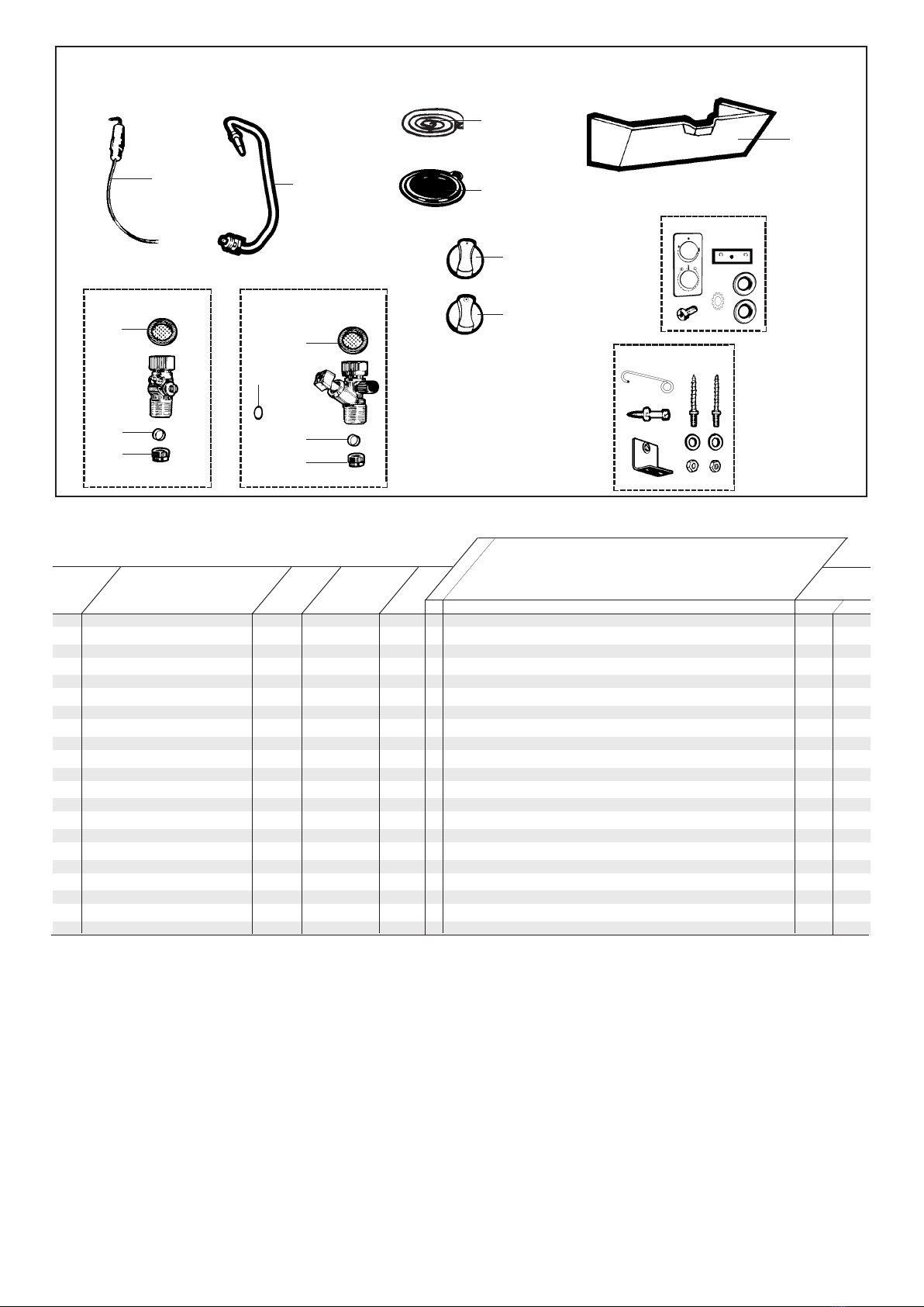
SHORT LIST
503
1038
1036
1019
165
634
930
931
907
1031
920
1006
1036
1043
1006
502
1001 1018
165 FOAM SEAL 25x12 L: 1.030M 366032 26773 .
502 THERMOCOUPLE 387251 35087 .
503 ELECTRODE & LEAD ASSY 387252 60703 .
634 DIAPHRAGM 263432 25809.30 .
907 FACIA KIT 264888 81172 HP .... 09/99
FACIA KIT 61400140 .02/03 ...
920 BOTTOM TRIM 1018809 .... 01/03
BOTTOM TRIM 61312266 .02/03 ...
930 GAS CONTROL KNOB 264487 74469 .... 01/03
GAS CONTROL KNOB 61312271 .02/03 ...
931 TEMPERATURE SELECTOR KNOB 264488 74470 .... 01/03
TEMPERATURE SELECTOR KNOB 61312270 .02/03 ...
1001 GAS SERVICE TAP KIT 265158 81288 NAT .
1006 COMPRESSION OLIVE 263800 56489 .
1018 WATER SERVICE TAP KIT 263794 81289 .
1019 WATER FILTER 277854 1007727 .
1031 FIXING ASSY 265160 81404 .
1036 NUT 1/2" 366642 56490 .
1038 GAS FILTER 263545 37309 .
1043 "O" RING D: 7.2-1.9 262806 24164.12 .
DescriptionKey N°
Manf. Pt. N°
Type
G.C N°
BF
Manf. date
BRITONY II T
from to
Chaffoteaux & Maury are continuously improving their products and therefore reserve the right to change specifications without prior
notice and accepts no liability for any errors or omission in the information contained in this document.
Manufacturer: Chaffoteaux & Maury - France
Commercial subsidiary: MTS (GB) Limited
MTS Building
Hughenden Avenue
High Wycombe
Bucks HP13 5FT
Telephone: (01494) 755600
Fax: (01494) 459775
Internet: www.chaffoteaux.co.uk
E-mail: [email protected]
Technical Support Help Line: 0870 241 8180
Customer Service Help Desk: 0870 600 9888
Table of contents
Other C&M Water Heater manuals


Popular Water Heater manuals by other brands
 user manual")


Rinnai
Rinnai Continuous Flow Water Heaters Operation manual

Giant
Giant RESIDENTIAL ELECTRIC WATER HEATER owner's manual

VEAB
VEAB WHS FITTING INSTRUCTION

Kenmore
Kenmore THE ECONOMIZER 153.333315 HA owner's manual

Solahart
Solahart Atmos Eco 180HAV Owner's guide and installation instructions

Grohe
Grohe Red Duo 30 058 Technical guide

iHeat
iHeat AHS11D Instruction and operation manual

Kenmore
Kenmore POWER MISER 153.336151 owner's manual

Kenmore
Kenmore 153.338003 owner's manual

Watts
Watts Aerco SmartPlate EV Installation, operation & maintenance manual

A.O. Smith
A.O. Smith BTN 120 THRU 400/A Series Installation and operaion manual

Sony
Sony VPL-CX75 Operation instructions