2| Cannon Balanced Flue Cannon Balanced Flue | 3
Installation Notes
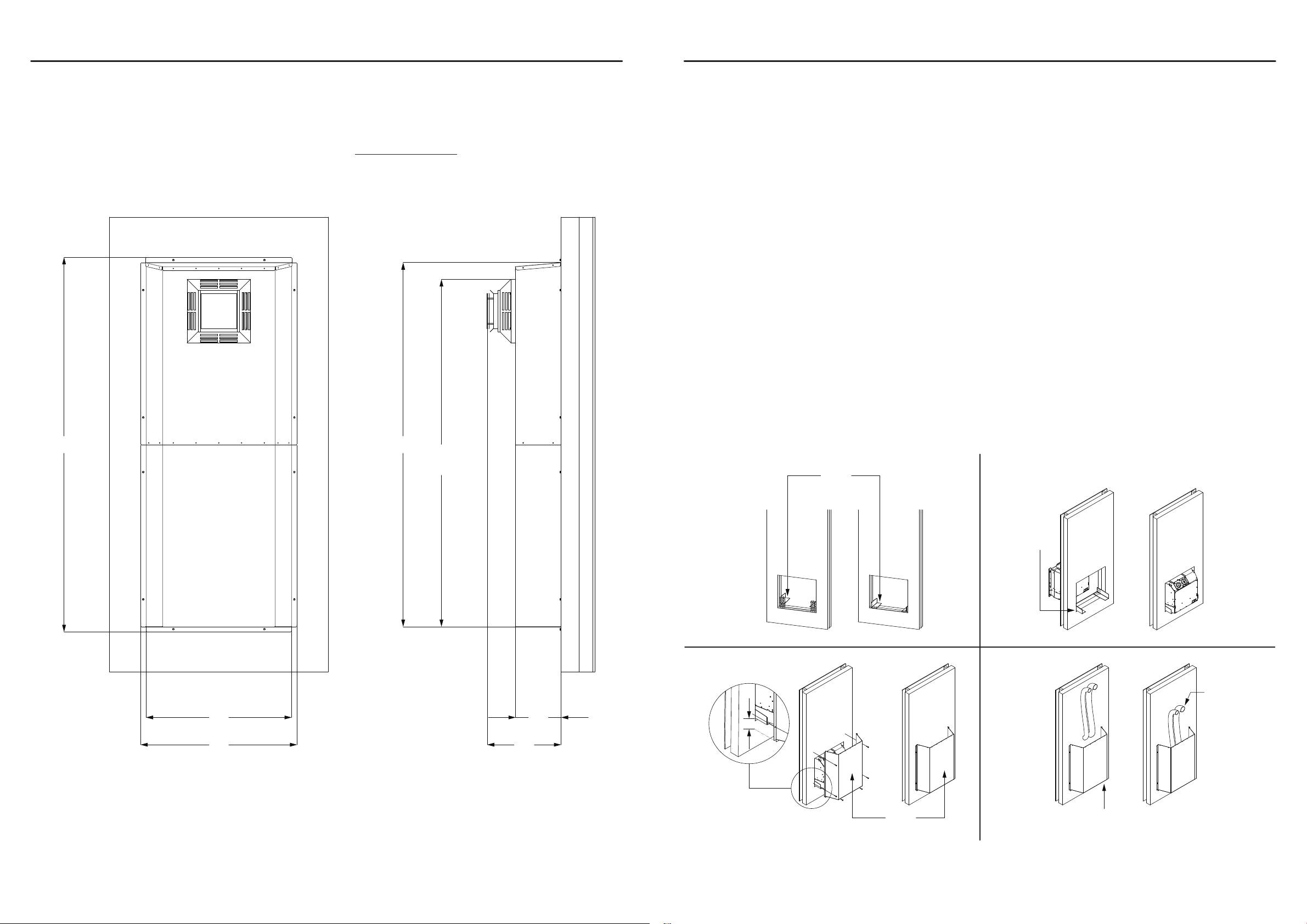
Dimensions (Flue Terminal Fitted)
Assembly Steps
Please follow the main installation instruction for wall cutout and following installation carefully.
Additional 12 fasteners to secure the weatherproof box to the outside wall have not been supplied. Pre-punched hole size is Ø9mm.
Step 1:
Secure support bracket into wall cavity against timber framing using wood screw (Ensure bracket is square and the distance between
brackets are slightly wider than the heater unit referred to in the installation instruction), as per Fig 1.
Step 2:
Insert heater through wall cavity. Heater should be rmly supported on the support brackets, as per Fig 2.
Step 3:
If wall socket is concealed inside cavity, connect the power cable at this point. If power supply cable is to be connected externally then
an appropriate weatherproof wall socket MUST be installed.
Step 4:
Fix and secure the lower section of the weatherproof box to the external wall, using suitable xtures to allow easy removal. The gap
between the heater and weatherproof box is 50mm, as per Fig 3.
Step 5:
Feed gas supply pipe through the weatherproof box and into the rear of heater, as per Fig 4.
Step 6:
Fit and secure the exible pipes onto the spigots on the heater, as per Fig 4.
Step 7:
Feed the exible pipes through the opening of the upper section of weatherproof box.
Step 8:
Align upper section of weatherproof box with lower section. Make sure the xing holes between the lower and upper tier are aligned for
the pop rivets to attach.
Support
Bracket
Support
Bracket
Lower
Section
Flexible
Pipe
Feed the
Gas Pipe
50mm
Gap
Fig 3
Fig 1
Fig 4
Fig 2
Installation Guide Installation Guide
1909
2000
406
249800
2060
860


