Canoga Perkins EdgeAccess UCS 1000 User manual

Universal Chassis System
UCS 1000
U
ser Manual


EdgeAccess Universal Chassis System
UCS 1000 i
CAUTION!
This product may contain a laser diode operating at a wavelength of 1300nm - 1600nm. Use of
optical instruments (e.g., collimating optics) with this product may increase eye hazard. Use of
controls or adjustments, or performing procedures other than those specified herein may result in
hazardous radiation exposure.
Under normal conditions, the radiation levels emitted by this product are under Class 1 limits in 21
CFR Chapter 1, Subchapter J.
ATTENCION!
Cet équipement peut avoir une diode laser émettant à des longueurs d'onde allant de 1300nm à
1600nm. L'utilisation d'instruments optiques (par exemple : un collimateur optique) avec cet
équipement peut s'avèrer dangereuse pour les yeux. Procéder à des contrôles, des ajustements ou toute
procédure autre que celles décrites ci-après peut provoquer une exposition dangereuse à des
radiations.
Sous des conditions normales, le niveau des radiations émises par cet équipement est en dessous des
limites prescrites dans CFR21, chapitre 1, sous chapitre J.
NOTICE!
This device contains static sensitive components. It should be handled only with proper ElectroStatic
Discharge (ESD) grounding procedures.
NOTE!
Cet équipement contient des composants sensibles aux décharges électro-statiques. Il doit absolument
être manipulé en respectant les règles de mise à la terre afin de prévenir de telles décharges.

EdgeAccess Universal Chassis System
UCS 1000
ii
NOTICE
Canoga Perkins has prepared this users manual for use by customers and Canoga Perkins personnel as
a guide for the proper installation, operation and/or maintenance of Canoga Perkins equipment. The
drawings, specifications and information contained in this document are the property of Canoga
Perkins and any unauthorized use or disclosure of such drawings, specifications and information is
prohibited.
Canoga Perkins reserves the right to change or update the contents of this manual and to change the
specifications of its products at any time without prior notification. Every effort has been made to
keep the information in this document current and accurate as of the date of publication or revision.
However, no guarantee is given or implied that the document is error free or that is accurate with
regard to any specification.
Canoga Perkins Corporation
20600 Prairie Street
Chatsworth, California 91311-6008
Business Phone: (818) 718-6300
(Monday - Friday 7 a.m. - 5 p.m. Pacific Time)
FAX: (818) 718-6312 (24hrs.)
Web Site: www.canoga.com
Email: [email protected]
Copyright©2000 - 2005 Canoga Perkins Corporation
All Rights Reserved
EdgeAccess®
Universal Chassis System
Model UCS 1000
User Manual
Product Number 6912200
Rev. F 09/2005
To reference Technical Advisories and Product Release Notes, go to Canoga Perkins'
website: http://www.canoga.com

EdgeAccess Universal Chassis System
UCS 1000 iii
Table of Contents
Chapter 1 Introduction........................................................................................... 1-1
Chapter 2 Installing and Setting Up the Chassis.................................................. 2-1
Chapter 3 Specifications ......................................................................................... 3-1
Physical Specifications ....................................................................................................................... 3-1
Regulatory Compliance ...................................................................................................................... 3-2
Appendix A Limited Warranty............................................................................. A-1
List of Figures
Figure 1. Populated UCS 1000 .......................................................................................................... 1-1
Figure 2. Chassis and Signal Ground Options................................................................................... 2-1
Figure 3. Mounting Bracket on Chassis............................................................................................. 2-2
Figure 4. Chassis Backplane and SW1, ID Switch............................................................................ 2-3
Figure 4. DC Power Supply Detail .................................................................................................... 2-4
List of Tables
Table 1. Power Supply(s) and Maximum Number of Modules......................................................... 1-2
Table 2. SW1, Chassis ID Switch...................................................................................................... 2-3
Table 3. Power Supply LEDs ............................................................................................................ 2-5

EdgeAccess Universal Chassis System
UCS 1000
iv

EdgeAccess Universal Chassis System
UCS 1000 1-1
Chapter 1
Introduction
The Model 1000 Universal Chassis System (UCS) Chassis houses and supplies power to Canoga
Perkins application modules. It accommodates modules that are 5U high and the Bus Access
Modules (BAMs) or Management Access Modules (MAMs) that house and supply power to
application modules that are 2U high.
Figure 1 shows some of the main Chassis components:
•The optional Domain Management Module (DMM) provides domain management
•The optional Chassis Management Module (CIM) provides alarm relays and management for
multiple chassis in the domain
•Individual application modules provide various network and transmission functions
•AC and DC power supply options provide power to the backplane and application modules
•An ESD grounding strap connector on the front of each power supply connects through the
chassis to Earth Ground.
Figure 1. Populated UCS 1000
The power supply options will determine how modules can be installed in each chassis. An AC
power supply requires two slots; up to two DC power supplies require one slot. Table 1 shows
maximum number of modules for each combination of power supplies.

EdgeAccess Universal Chassis System
UCS 1000
1-2
Table 1. Power Supply(s) and Maximum Number of Modules
AC Power
Supplies
DC Power
Supplies
Allows This
Many Modules
None 1 or 2 15
1 None 14
1113
2 None 12
By itself, the chassis cannot generate a power failure alarm. If you install a CIM, which includes
alarm circuitry and connectors, you can connect an external device to the CIM in order to provide
alarm information to a person or an environment away from the chassis. For details, see the Model
1200 Chassis Interconnect Module User Manual.

EdgeAccess Universal Chassis System
UCS 1000 2-1
Chapter 2
Installing and Setting Up the Chassis
This section describes how to set up the chassis, including power supply options, mounting, cabling,
and powering up the chassis.
Caution: Equipment intended only for installation in a RESTRICTED ACCESS LOCATION
accessible only to electrically skilled persons and electrically instructed persons with
the proper authorization.
1. Plan the installation, considering these characteristics:
•Place the chassis within 7 ft. (2.134 m) of the power source.
•Plan to use one or more of these locations for the connection to Earth Ground:
•The bonding lug on the rear of the chassis, near the bottom
•The grounding prong on the AC power cord
•The ground side of the -48 VDC terminal strip
•The mounting hardware for the rack, if the rack is tied to Earth Ground
•Place the chassis adjacent to other Canoga Perkins or related equipment.
•Allow room for the cable management bracket(s) that channel the cables, allowing slack in the
cables and providing a surface for securing with a tie-wrap.
•Leave at least a 1U space between the chassis any other equipment for adequate ventilation; a
positive airflow cabinet is recommended. If the environment has little air flow or the chassis and
other equipment are closely spaced or heavily loaded, use the optional fan tray to ensure adequate
cooling. For details, contact Canoga Perkins Technical Support.
2. Unpack the chassis and inspect all components. Save the shipping carton and packing materials
in case you need to return the equipment to the manufacturer. Appendix A provides information
for Return Material Authorization (RMA).
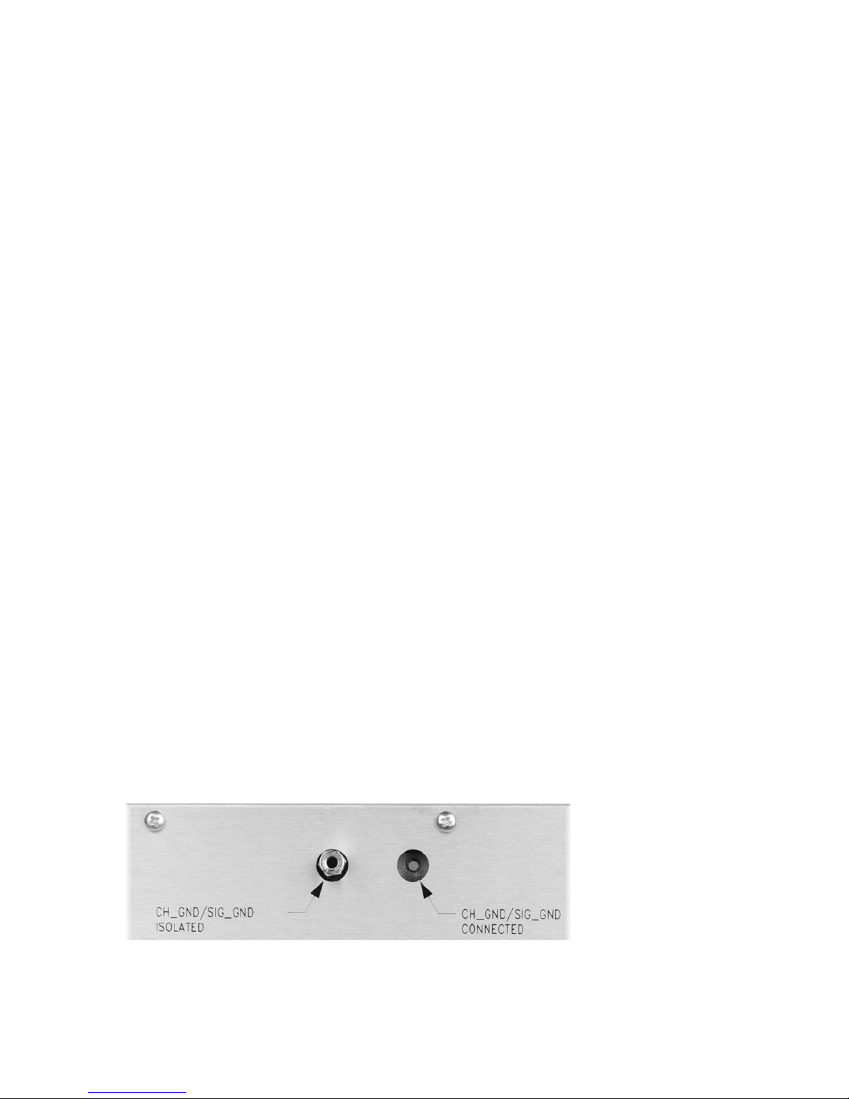
3. Set the chassis and signal ground option located on the rear of the chassis, near the top. See
Figure 2.
•To isolate the grounds for the chassis and the signal, screw the shorting plug into
CS_GND/SIG_GND ISOLATED.
•To connect the grounds for the chassis and the signal, screw the shorting plug into
CS_GND/SIG_GND CONNECTED.
Figure 2. Chassis and Signal Ground Options

EdgeAccess Universal Chassis System
UCS 1000
2-2
4. To connect Earth Ground to the bonding lug on the rear of the chassis, near the bottom, move the
chassis adjacent to the installation area, then plug the Earth Ground wire into the bonding lug.
5. You can mount the chassis in a standard 19-inch relay rack, in a 23-inch rack using optional
brackets, or place it on a flat, secure surface.
•To mount the chassis in a 19-inch rack, position the chassis in the rack, then attach the
bracket to the rack with four screws.
•To mount the chassis in a 23-inch rack, replace the standard bracket with the optional
mounting bracket, then attach that bracket to the rack with four screws; see Figure 3.
•To place the chassis on a flat, secure surface, turn the chassis upside down, mount the self-
adhesive feet at the four corners of the bottom for the chassis, then turn the chassis right-side
up. Keep a space around the chassis to allow airflow.
Three screws mount the
bracket on the chassis
Figure 3. Mounting Bracket on Chassis
If the system includes two or more chassis that are connected through a CIM in each chassis, each
chassis must be set to a unique ID number.
6. Locate SW1 inside the chassis at the upper left of the backplane; see Figure 4.
Caution: Make sure that the chassis power is off or disconnected. Use a non-conductive device
to set SW1.
7. Set SW1 to the ID number for this chassis according to the information in Table 2.

EdgeAccess Universal Chassis System
UCS 1000 2-3
Figure 4. Chassis Backplane and SW1, ID Switch
Table 2. SW1, Chassis ID Switch
Chassis ID CID0 CID1 CID2
1 Closed Closed Closed
2 Open Closed Closed
3 Closed Open Closed
4 Open Open Closed
5 Closed Closed Open
6 Open Closed Open
7 Closed Open Open
8 Open Open Open
8. Set SW1, CH-DCPS, to match the primary power supply in the chassis. See Figure 4.
•For DC Power, set SW1, CH-DCPS to Open.
•For AC Power, set SW1, CH-DCPS to Closed.

EdgeAccess Universal Chassis System
UCS 1000
2-4
If the chassis uses DC power, it requires a bracket in the end slot at the right side of the chassis.
Install the primary DC supply in the top slot in the bracket and a redundant DC supply in the lower
slot in the bracket. If the chassis includes a redundant AC power supply, install it in the next slot to
the left. See Figure 1; it shows a DC power supply with a secondary AC supply.
If the chassis uses only AC power, install the primary AC supply in the end slot at the right side of the
chassis. If the chassis includes a redundant AC power supply, install it in the next slot to the left...
9. To install a power supply, turn the power switch off and unplug any power cords or cables.
10. Slide the power supply firmly into the slot and tighten the captive Philips screws. to secure it.
Caution: In a redundant DC configuration, both DC sources must have the same ground
potential.
11. Make sure the external power source is off, then connect the power for your power supply.
•For an AC supply, plug in the power cord.
•For a DC supply, attach the GND and -VDC power cables to the screw terminal and re-install
the protective cover. See Figure 4.
Figure 4. DC Power Supply Detail
For details about installing the optional CIM and DMM, see the user manuals for the CIM and DMM.
12. Install the optional CIM in the bottom position in slot 0. See Figure 1.
13. Install the optional DMM the top position in slot 0. See Figure 1.
14. If the chassis does not include a CIM or DMM, install cover(s) on the unused slots.
15. Turn on the chassis power supply(s).
Note: The DC power-up delay may be up to eight seconds.
16. Check the LEDs on the power supply(s). Table 3 lists the LEDs and their meanings.

EdgeAccess Universal Chassis System
UCS 1000 2-5
Table 3. Power Supply LEDs
LED Color Description
DC Power Off No power
Amber Soft start delay
Green Normal operation
AC Power Off No power
Green Normal operation
The chassis is ready for installing the system modules. All modules are hot-swappable and can be
inserted or removed at any time without affecting other modules in the chassis.

EdgeAccess Universal Chassis System
UCS 1000
2-6

EdgeAccess Universal Chassis System
UCS 1000 3-1
Chapter 3
Specifications
Physical Specifications
Dimensions
Chassis 8.75" H x 19" W x 11.75" D (222 mm x 482 mm x 264 mm)
AC Power Supply 8.5" H x 1.7" W x 11.5" D (216 mm x 43 mm x 292 mm)
Weight
Chassis, unpopulated 12 lb. (5.45 kg)
AC Power Supply 5 lb. (2.27 kg)
DC Power Supply 1 lb. (0.45 kg)
Mounting 19-inch rack
23-inch rack (with optional brackets)
Operating Temperature 0-40°C with convection cooling, 0-50°C with fan tray
Humidity Up to 95% (non-condensing)
Power
AC 150 W, 90 to 264 VAC @ 2 A max 50/60 Hz input
Front panel switch rated at 4 A continuous and 5 A up to 25 sec
DC 150 W, -36 to -58 VDC @ 3 A max input
Front panel switch rated at 5A
Total power consumption 150 W, max
Backplane -36 to -58 VDC input, 180 mA, max, per slot
Redundancy Optional, AC/AC, DC/DC or AC/DC
Fan -48 VDC, cooling fan power connector located on the CIM
Caution: Equipment intended only for installation in a RESTRICTED ACCESS LOCATION
accessible only to electrically skilled persons and electrically instructed persons with
the proper authorization.

EdgeAccess Universal Chassis System
UCS 1000
3-2
Regulatory Compliance
•ETL, cETL (UL 60950/CAN/CSA-C22.2 No.60950, EN/IEC 60950) IEC 60825-1
•FCC Part 15B/IC-003/VCCI Class A
•C-Tick (AS/NZS 3548)
•EN 55022 Class A
•EN 61000-3-2, EN 61000-3-3
•EN 50024
•FCC Part 68/IC CS-03/TS-016
•CTR 12, CTR 13, NTR 4
•R&TTE Directive (EN 300 386)
•NEBS Level 3
•CE Mark

EdgeAccess Universal Chassis System
UCS 1000 A-1
Appendix A
Limited Warranty
Limited Lifetime Warranty
Effective July 1, 2005 and After,Canoga Perkins warrants that, at the time of sale, and, for its lifetime,
with certain exceptions noted below, every Canoga Perkins' labeled product purchased will be free from
defects in material and workmanship for its lifetime, if properly installed and used in conformity to Canoga
Perkins' published specifications. This warranty covers the original user only and is not transferable. For
the purposes of this Warranty, "lifetime" is defined as the serviceable life of the product (a minimum of 5
years) or any longer period during which replacement spare parts are available. Subject to the conditions
and limitations set forth below, Canoga Perkins will, at its option, either repair or replace any part of its
product(s) that prove defective by reason of improper workmanship or materials. The warranty period for
power supplies, fans and optics is five (5) years. Consumables such as filters are covered for one year.
Software is warranted for 90 days. Hardened Media Converter (HS) products are covered for three (3)
years.
This warranty does not cover any damage to products that have been subjected to lightning or other Acts of
Nature, misuse, neglect, accident, damage, improper installation, or maintenance, including over-voltage
failures caused by use outside of the product's specified rating, normal wear and tear of mechanical
components, or alteration or repair by anyone other than Canoga Perkins or its authorized representative. If
the user is unsure about the proper means of installing or using the equipment, contact Canoga Perkins' free
technical support services. Customer must notify Canoga Perkins promptly in writing of any claim based
on warranty. Canoga Perkins is not liable for, and does not cover under warranty, any costs associated with
servicing and/or the installation of its products or for any inspection, packing or labor costs in connection
with return of goods. In the event Canoga Perkins breaches its obligation of warranty, customer's sole and
exclusive remedy is limited to replacement, repair, or credit of the purchase price, at Canoga Perkins'
option. Under no circumstance will Canoga Perkins be liable for consequential or incidental damages or
loss of profits.
Warranty Registration
To establish original ownership and to record purchase date, please complete the warranty on-line form on
our product registration page. URL: www.canoga.com/warranty
Optional Service Programs
Canoga Perkins offers several optional Service Programs. Please call Canoga Perkins Sales Department
(818-718-6300) or see our web site (www.canoga.com) for details.
CUSTOMER SERVICE DEPARTMENT REPAIR WARRANTY
Repairs performed by the Canoga Perkins Customer Service Department will be free from defects in
material and workmanship for a period of ninety (90) DAYS from the date the repaired product is shipped,
or until the expiration of the original factory warranty, whichever is longer.

EdgeAccess Universal Chassis System
UCS 1000
A-2
Limitations
Canoga Perkins may at its sole discretion modify its Limited Warranty at any time and from time to time.
Other than those expressly stated herein, THERE ARE NO OTHER WARRANTIES OF ANY KIND,
EXPRESSED OR IMPLIED, AND SPECIFICALLY EXCLUDED BUT NOT BY WAY OF
LIMITATION, ARE THE IMPLIED WARRANTIES FOR FITNESS FOR A PARTICULAR PURPOSE
AND MERCHANTABILITY. IT IS UNDERSTOOD AND AGREED CANOGA PERKINS' LIABILITY
WHETHER IN CONTRACT, IN TORT, UNDER ANY WARRANTY, IN NEGLIGENCE OR
OTHERWISE SHALL NOT EXCEED THE AMOUNT OF THE PURCHASE PRICE PAID BY THE
CUSTOMER AND UNDER NO CIRCUMSTANCES SHALL CANOGA PERKINS BE LIABLE FOR
SPECIAL, INDIRECT, INCIDENTAL OR CONSEQUENTIAL DAMAGES. THE PRICE STATED FOR
THE EQUIPMENT IS A CONSIDERATION IN LIMITING CANOGA PERKINS' LIABILITY. NO
ACTION, REGARDLESS OF FORM, ARISING OUT OF THE TRANSACTIONS OF THIS
AGREEMENT MAY BE BROUGHT BY CUSTOMER MORE THAN ONE YEAR AFTER THE
CAUSE OF THE ACTION HAS ACCRUED. CANOGA PERKINS' MAXIMUM LIABILITY SHALL
NOT EXCEED AND CUSTOMER'S REMEDY IS LIMITED TO EITHER (i) REPAIR OR
REPLACEMENT OF THE DEFECTIVE PART OF PRODUCT, OR AT CANOGA PERKINS' OPTION
(ii) RETURN OF THE PRODUCT AND REFUND OF THE PURCHASE PRICE, AND SUCH REMEDY
SHALL BE CUSTOMER'S ENTIRE AND EXCLUSIVE REMEDY. AUTHORIZED RESELLERS ARE
NOT AUTHORIZED TO EXTEND ANY DIFFERENT WARRANTY ON CANOGA PERKINS'
BEHALF.
Return Policy
Customer must obtain an RMA (Return Material Authorization) number from the Canoga Perkins
Customer Service Department before returning a product for service or repair.
Canoga Perkins' technical support department can be reached through any of the following means:
Telephone: 818-718-6300
Fax: 818-718-6312
E-Mail: fiber@canoga.com
If the warranty for a power supply, fan, optics, consumable or software has expired, customer must provide
the Canoga Perkins Customer Service Representative with a Purchase Order to authorize the repair.
Send the defective product postage and insurance prepaid to the address provided to you by Canoga
Perkins' technical support representative. Failure to properly protect the product during shipping may void
this warranty. The return authorization number must be written on the outside of the carton to ensure its
acceptance.
The customer must pay for the non-compliant product(s) return transportation costs to Canoga Perkins for
evaluation of said product(s) for repair or replacement. Canoga Perkins will pay for the shipping of the
repaired or replaced in-warranty product(s) back to the customer (any and all customs charges, tariffs,
or/and taxes are the customer's responsibility).
Canoga Perkins reserves the right to charge for all testing and shipping incurred, if after testing, a return is
classified as "No Problem Found."


CANOGA PERKINS CORPORATION
20600 Prairie Street
Chatsworth, California 91311-6008 USA
Phone: (818) 718-6300 FAX: (818) 718-6312
Web Site: www.canoga.com
Email: [email protected]
Table of contents