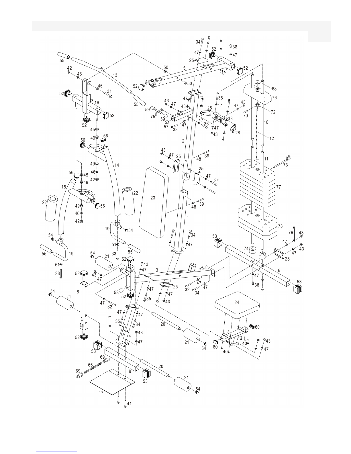
Cap Strength FM-H1007A125 User manual

1
OWNER’S MANUAL
300 LB
HOME GYM
With 125 lb weight stack
Maximum Wei
g
ht Ca
p
acit
y,
includin
g
User:
Model Numbe
r
FM-H1007A125
UPDATED: 09/26/2012
QUESTIONS?
Call: 1-877-227-0955
Email: customerservi[email protected]
Website: www.capbarbell.com
CAP Barbell
10820 Westpark Dr.
Houston, TX 77042
WARNING: SERIOUS INJURY OR
DEATH AN OCCUR IF CAUTION IS NOT USED.
To reduce the risk of serious injury, read all
important precautions and instructions in this
manual and all warnings on your product before
using it. Keep this manual for future reference.
FOR CONSUMER USE ONLY
Serial No: _____________________
Write the serial Number in the space above for
future reference

2
TABLE OF CONTENTS
SECTION
1 ................................................................................................................................WARNING DECAL PLACEMENT
2 ............................................................................................................................................IMPORTANT WARNINGS
3..........................................................................................................MAIN PARTS AND ASSEMBLED DIMENSIONS
4.................................................................................................................................PART IDENTIFICATION CHART
5 ..................................................................................................................................................................PARTS LIST
6................................................................................................................................................ EXPLODED DRAWING
7 ...................................................................................................................................................................ASSEMBLY
8 ..............................................................................................................................................EXERCISE GUIDELINES
9 .............................................................................................................................................................MAINTENANCE
10............................................................................................................................... OPERATIONAL INSTRUCTIONS
11……………..…................…………….....…………………………………………………………....LIMITED WARRANTY
1. WARNING DECAL PLACEMENT
This drawing shows the location of the
warning decal(s). If a decal is missing or
illegible, see the front cover of this
manual and request a replacement
decal. Apply the decal in the location
shown. Note: The decal(s) may not be
shown at actual size.

3
2. IMPORTANT WARNINGS
WARNING: SERIOUS INJURY OR DEATH CAN OCCUR IF CAUTION IS NOT USED. To reduce the risk of serious
injury, read all important precautions and instructions in this manual and all warnings on your product before using it.
Before beginning any exercise program, consult your physician. This is especially important for persons over age 35
or persons with pre-existing health problems.
1. Read all instructions in this manual and all warnings on the product before using it. Use this product only as
described in this manual and keep this manual handy for future reference.
2. It is the responsibility of the owner to ensure that all users of this product are adequately informed of all
precautions.
3. Keep children away from this product at all times. Parents or others supervising children must provide close
supervision of children if the equipment is used in the presence of children.
4. The weight stack or top plate should never be pinned in an elevated position. The machine must not be used if
found in this condition
5. Be certain that the weight pin is completely inserted.
6. Inspect the machine for worn or loose components prior to use. Tighten/replace any loose or worn components
prior to using.
7. Pay close attention to ropes, belts, or chains and their connections.
8. Never use dumbbells or other means to incrementally increase the weight resistance. Use only those means
provided by the manufacturer.
9. Set up and operate the home gym on a solid level surface with at least 3 feet of clearance around it.
10. Do not wear loose or dangling clothing or jewelry while using the home gym. Stay clear of all moving
components.
11. Consult your physician prior to commencing an exercise program.
12. Over exercising may result in serious injury or death. If you feel faint, dizzy, or experience pain while exercising,
stop immediately, cool down and/or consult your physician.
13. This product is intended for consumer-use only and in an indoors environment. Do not use it in a commercial,
rental, or institutional setting.
14. Do not exceed the maximum specified user weight.
15. This machine meets industry standards for stability when used for its recommended purpose in accordance with
the instructions provided by the manufacturer.
16. Using the machine for support during stretching or allowing resistance straps, ropes, or other means to be
attached to it may result in serious injury.
17. The weight stack has a lock out mechanism which must be secured after each use of the machine to prevent the
inadvertent use by children.
MAXIMUM WEIGHT CAPACITIES
These are the maximum weight capacities recommended by the manufacturer. Use Caution when exercising and
always workout with safety in mind. Serious injury or death can occur if these warnings are not followed. Never
exercise alone.
Maximum Weight Capacity for Bench Including User = 300 lbs (136 kg)

4
3. MAIN PARTS AND ASSEMBLED DIMENSIONS
If you have any questions after reading this manual, please see the front cover of this manual or call 1-877-227-0955
for assistance. To help us assist you, note the product model number before contacting us. Before reading further,
please familiarize yourself with the parts that are labeled in the drawing below.
*Set up and operate the home gym on a solid level surface with at least 3 feet of clearance around it. This product is
for consumer-use only. Do not use it in a commercial setting.
ASSEMBLED DIMENSIONS AND WEIGHT
Width Depth Height Weight
IN 46.06 33.27 83.46 198.36 Lb
CM 117 84.50 212 90.00 Kg

5
4. PART IDENTIFICATION CHART
Assembly requires two persons. Place all parts in a cleared area and remove the packing materials. Do not dispose
of the packing materials until assembly is completed. See below a list of tools that are included with your product. In
addition to the included tools, assembly may require a Phillips screwdriver, an adjustable wrench, and a
rubber mallet (not included). See the drawings below to identify the small parts needed for assembly. Note: If a
part is not in the hardware kit, check to see if it has been preassembled. To avoid damaging parts, do not
use power tools for assembly.
Not included

6
1. PARTS LIST
No. Part No. Description Qty. No. Part No. Description Qty.
1 PFMH1007A-01 Bottom Main Frame Support 1 41 PFMH1007A-28 M10 x 65mm Carriage Bolt 2
2 PFMH1007A-02 Top Main Frame Support 1 42 PRK3E-04 M12 Nylon Locknut 3
3 PFMH1007A-03 Base Frame 1 43 PRK1-05 M10 Nylon Locknut 33
4 PFMH1007A-04 Front Stabilizer Bar 1 44 PFMH1001-37 M10 Nut 2
5 PFMH1007A-05 Top Frame 1 45 PFMH1005-36 M16 Washer 2
6 PFMH1007A-06 Horizontal Beam 1 46 PRK3E-05 M12 Washer 4
7 PFMH1007A-07 Seat Support 1 47 PRK1-06 M10 Washer 68
8 PFMH1007A-08 Leg Extension 1 48 PFM2006-27 M8 Washer 2
9 PFMH1007A-09 Front Stabilizer 1 49 PFMH1005-37 Inner Washer #16.5 4
10 PFMH1007A-10 Top Guide Rod 2 50 PFMH1001-46 Inner Washer #12.5 2
11 PFMH1007A-11 Bottom Guide Rod 2 51 PFM2006-28 M10 Curved Washer 2
12 PFMH1007A-12 Selector Shaft 1 52 PRK3-05 50mm Square Inner Cap 10
13 PFMH1007A-13 Lat Bar 1 53 PRK13-04 50mm Square End Cap 4
14 PFMH1007A-14 Left Arm 1 54 PRK1-03 25mm Round Inner Cap 6
15 PFMH1007A-15 Right Arm 1 55 PFM2007-08 25*130mm Handle 4
16 PFMH1007A-16 Press Arm Junction 1 56 PFM2004-09 50mm Round Inner Cap 4
17 PFMH1007A-17 Front Treadle 1 57 PFMH1005-40 Cushion 1
18 PFMH1007A-18 Pulley Immobility Tube 1 58 PFM2240-19 25mm Round Angled Cap 1
19 PFMH1007A-19 Press/Fly Handle 2 59 PFMH1007A-29 Rubber Cap 2
20 PFMH1007A-20 Foam Roller Tube 2 60 PFMH1005-39 25*50 Square Plastic Cap 2
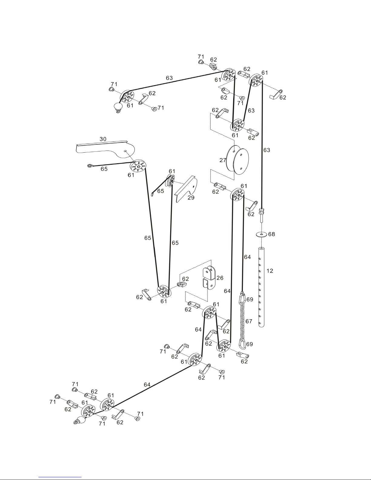
21 PFMH1005-20 Foam Roll 4 61 PFMG3008-13 Pulley Wheel 13
22 PFMH1005-21 Foam Arm Rest 2 62 PFMH1007A-30 Pulley Guide Sleeve 20
23 PFMH1007A-21 Back Cushion 1 63 PFMH1007A-31 Top Cable 1
24 PFMH1007A-22 Seat Rest 1 64 PFMH1007A-32 Bottom Cable 1
25 PFMH1007A-23 Enforcements 5 65 PFMH1007A-33 Peck Dec Cable 1
26 PFMH1001-16 Pulley Bracket B 1 66 PFM3008-19 Long Chain 1
27 PFMH1007A-24 Pulley Panel 2 67 PFM3008-19 Short Chain 1
28 PFMH1001-14 Pulley Bracket C 2 68 PFMH1001-43 Washer 1
29 PFMH1007A-25 Left Safeguard Cover 1 69 PFM2241-12 Snap Hook 4
30 PFMH1007A-26 Right Safeguard Cover 1 70 PFMH1001-44 Top Plate Pin 1
31 PFMH1007A-27 M12 x 80mm Bolt 1 71 PFMS80-13 Top Hat Bush 10
32 PFM2101-23 M10 x 75mm Bolt 2 72 PFMH1001-45 Plastic Cap 1
33 PFMH1005-31 M10 x 90mm Bolt 3 73 PFMH1001-25 P Pull Pin 1
34 PRK1B-06 M10 x 70mm Bolt 13 74 PFMH1007A-34 Rubber Bumper 2
35 PFM2240-22 M10 x 65mm Bolt 4 75 PFMH1007A-35 L Type Screw 1
36 PFM2005-29 M10 x 45mm Bolt 9 76 PFMH1007A-36 5lb Top Plate 1
37 PFMH1001-41 M10 x 35mm Bolt 2 77 PFMH1007A-37 10lb Weight Stack 7
38 PFM404-18 M10 x 20mm Bolt 4 78 PFMH1001-28 15lb Weight Stack 3
39 PFMH1005-32 M8 x 65mm Bolt 2 79 PFMH1007A-38 Safety Wire 1
40 PFM2240-23 M6 x 15mm Screw 4
Note: Specifications are subject to change without notice. For information about ordering replacement parts, see
the front cover of this manual.

7
6. EXPLODED VIEW

8
EXPLODED VIEW OF CABLE SYSTEM

9
7. ASSEMBLY
Step 1:
Connect the base frame (3) to the horizontal beam (6)
by using bolts (32&34), washers (47), enforcement (25)
and locknuts (43)
Step 2:
Connect the front stabilizer bar (4) to front stabilizer (9)
and front treadle (17) by using bolts (41), washers (47),
and locknuts (43)
Step 3:
Connect base frame assembly(3) to front stabilizer bar
assembly (4) and seat support (7) by using bolts (34&35),
washers (47), and locknuts (43)
Step 4:
Slide bottom guide rods (11) into the rubber bumpers (74)
and through the horizontal beam (6) fasten by using bolts (38)
and washers (47). Insert top guide rods (10) into bottom guide
rods (11). (Note: It is optional to postpone inserting the top
guide rods into the bottom guide rods until after step 5 to make
installation of the weight stacks easier).

10
Step 5:
Starting with the 15lb weight stack (78) then the 10lb weight
stack (77), place the weight stacks onto the guide rods (11&12).
Once done, connect the selector shaft (12) to the top plate (76)
with the plastic cap (72) top plate pin (70) and washer (68).
Then slide the entire piece onto the guide rods (11&12).
Finally, use the P pull pin (73) to secure the shaft into the
weight stack.
Step 6:
Insert the leg extension (8) into the arms coming off of
the base frame assembly (3). Fasten using bolt (32),
washers (47), and locknuts (43).
Step 7:
Vertically place the bottom main frame support (1)
onto the base frame (3). Secure it using bolts (34),
washers (47), enforcement (25) and locknuts (43).
Insert the top main frame support (2) into the bottom
main frame support (1) and secure using bolts (34),
washers (47), enforcements (25) and locknuts (43).
Step 8:
Attach the pulley immobility tube (18) to the upper main
frame support (2) with bolt (33), washers (47) and locknut
(43). Attach pulley brackets C (28) to either side of pulley
immobility tube (18) with bolts (35), washers (47) and
locknuts (43). (Note: Do not over tighten, allow pulley
brackets to move freely)

11
Step 9:
Attach the top frame (5) making sure that it is aligned
correctly to the guide rods (10) and to top frame main
support (2). Then secure using bolts (34&38), washers (47),
enforcement (25) and locknuts (43).
Step 10:
Install the L type screw (75) into the bracket on the arm
of the top main frame support (2) using bolt (36), washers (47)
and locknut (43). Next, install the inner washers #12.5 (50)
into the holes on the top frame (5). Connect the press arm
junction (16) to the top frame (5) using bolt (31), washers (46)
and locknut (42).
Step 11:
Slide the foam arm rests (22) onto both arms (14&15) then
attach press/fly handles (19) to arms using bolt (33) and
curved washers (51). Connect both assembled arms (14&15)
to the press arm junction (16) using inner washers #16.5 (49),
washers (45&46), and locknut (42).
Step 12:
Attach the back cushion (23) by using bolts (39) and washers (48).

12
Step 13:
Attach the seat rest (24) to the seat support (7) by using
screws (40).
Step 14:
Insert foam roller tubes (20) into the base frame (3) and leg
extension (8). hen slide foam rolls (21) onto the foam roller
tubes (20).
Step 15:
Stick bolt (37) through the curved/bent part of the left
arm (14) then place washers (47), nut (44), pec deck
cable (65) around the bolt (37) and tighten with locknut (43).
(Note: pec deck cable has a metal ring on each end)
Step 16:
Place the pec deck cable (65) within the grooves of the pulley
wheel (61). Then align the pulley wheel (61) between the
teeth of the pulley bracket C (28). Align left safeguard cover (29)
with the pulley wheel (61) and pulley bracket C (28) and secure
by using bolt (36), washers (47) and locknut (43).

13
Step 17:
Using another pulley wheel (61) place the pec deck cable (65)
within the grooves and then attach pulley bracket B (26) and
pulley guide sleeves (x2) to the wheel and secure by using
bolt (36), washers (47) and locknut (43).
Step 18:
Using the same pec deck cable (65), bring it back and fit it
around another pulley wheel (61). Align the pulley wheel (61)
between the teeth of the pulley bracket C (28). Align right
safeguard cover (30) with the pulley wheel (61) and pulley
bracket C (28) and secure by using bolt (36), washers (47)
and locknut (43).
Step 19:
Align the top cable (63) with another pulley wheel (61). Then
attach the pulley to the top frame (5) with bolt (34), washers
(47), top hat bushings (71), pulley guide sleeve (62) and locknut
(43). Attach snap hooks (69) to either end of the long chain (66).
Then open snap hooks and attach the lat bar (13) to chain.
Attach assembly to the ball end of the top cable (63).
(Note: top cable has a screw connected at one end and a ball
on the other end.)
Step 20:
Pull the top cable (63) and align it with the top of the pulley
wheel (61). Insert the pulley into the space at the top frame (5)
and then attach the pulley to the top frame (5) with bolt (34),
washers (47), top hat bushings (71), pulley guide sleeve (62)
and locknut (43).

14
Step 21:
Using the excess cable from the last step, place the cable
underneath another pulley wheel (61). Secure the pulley
wheel (61) and pulley guide sleeves (62) between the
pulley panels (27) with bolt (36), washers (47), and
locknut (43).
Step 22:
Continue assembly with the same cable and place it above
another pulley wheel (61), then secure it and pulley guide
sleeves (62) between the hanging teeth on the top frame (5)
with bolt (36), washers (47), and locknut (43). Next, pull the
end of the cable (63) and screw it into the selector shaft (12)
using the washer (68).
Step 23:
Align the bottom cable (64) underneath a pulley wheel (61).
Insert both the pulley and a pulley guide sleeve (62) through
the hole in the leg extension (8). Secure into place with bolt (34),
washer (47), top hat bushings (71), and locknut (43). Pull the
bottom cable (64) through the front stabilizer bar (4) and align it
underneath another pulley wheel (61) and secure it and the pulley
guide sleeves (62) into place as shown.
Step 24:
Align the bottom cable (64) underneath another pulley wheel (61)
and insert both the pulley and a pulley guide sleeves (62) into the
hole in base frame (3). Secure into place with bolt (34), washer
(47), top hat bushings (71), and locknut (43). Continue to pull the
bottom cable (64) up through the hole in the base frame (3). Then
route the cable above another pulley wheel (61) and secure it and
the pulley guide sleeves (62) to the partially assembled pulley
bracket B (26) as shown.

15
Step 25:
Align the same cable underneath another pulley wheel (61) and
attach it and pulley guide sleeves to the teeth extending upwards
from the base frame (3). Secure into place with bolt (36), washer
(47), and locknut (43).
Step 26:
Align the same cable above another pulley wheel (61). Secure the
pulley wheel (61) and pulley guide sleeves (62) between the pulley
panels (27) with bolt (36), washers (47), and locknut (43). Attach
snap hooks (69) to either end of the short chain (67). Attach the
chain to the bottom cable (64) Then open snap hooks and attach
the assembly to the tab welded to the base frame.
Step 27:
To lock the home gym in “safe position” insert the P pull pin (73) through the loop in the safety wire (79) and push
into the lowest hole of the selector shaft (12). This will keep the stack from moving, and will need to be removed
before the next exercise period.
WARNING:
Make sure the lock out mechanism for the weight stack is secured after each use of the machine to prevent the
inadvertent use by children.

16
8. EXERCISE GUIDELINES
Each workout should include 6 to 10 different exercises. Select exercises for every major muscle group, emphasizing
areas that you want to develop most. To give balance and variety to your workouts, vary the exercises from session
to session. Schedule your workouts for the time of day when your energy level is the highest. Each workout should
be followed by at least one day of rest. Once you find the schedule that is right for you, stick with it.
EXERCISE FORM
Maintaining proper form is an essential part of an effective exercise program. This requires moving through the full
range of motion for each exercise, and moving only the appropriate parts of the body. Exercising in an uncontrolled
manner will leave you feeling exhausted. The repetitions in each set should be performed smoothly and without
pausing. The exertion stage of each repetition should last about half as long as the return stage. Proper breathing is
important. Exhale during the exertion stage of each repetition and inhale during the return stroke. Never hold your
breath.
Rest for a short period of time after each set. The ideal resting periods are:
Rest for three minutes after each set for a muscle-building workout.
Rest for one minute after each set for a toning workout.
Rest for 30 seconds after each set for a weight loss workout.
Plan to spend the first couple of weeks getting familiar with the equipment and learning the proper form for each
exercise.
COOLING DOWN
End each workout with 5 to 10 minutes of stretching. Include stretches for both your arms and legs. Move slowly as
you stretch and do not bounce. Ease into each stretch gradually and go only as far as you can without strain.
Stretching at the end of each workout is an effective way to increase flexibility.
STAYING MOTIVATED
For motivation, keep a record of each workout. List the date, the exercises performed, the resistance used, and the
numbers of sets and repetitions completed. Record your weight and key body measurements at the end of every
month. Remember, the key to achieving the greatest results is to make exercise a regular and enjoyable part of your
everyday life.

17
9. MAINTENANCE
The safety and integrity designed into the machine can only be maintained when the equipment is regularly examined for damage
and repaired. It is the sole responsibility of the user/owner to ensure that regular maintenance is performed. Worn or damaged
components shall be replaced immediately and stop using the equipment until the repair is made. Only manufacturer supplied
components shall be used to maintain/repair the equipment.
1. Wipe the home gym regularly to prevent accumulation of dust.
2. Use a damp cloth on plastic parts only, use dry cloth on metal frames.
3. Upholstery: Wipe down all upholstery with a damp cloth as needed.
4. Avoid acid chlorine based cleaners and also cleaners containing abrasives as these could scratch or damage the equipment
5. Pay close attention to wear and tear of ropes, belts, or chains and their connections.
6. Keep this product indoors, away from moisture and dust. Do not put it in a garage or covered patio, or near water.
7. Check regularly to ensure all parts are tight and in working condition. If a part is damaged do not use until the part is
replaced or repaired.
8. Place the home gym on a level surface with a mat beneath it to protect your floor or carpet
9. Do not install any fitness product near a pool, hot tub or other damp locations. Corrosion caused by installation in these
locations can lead to premature failure of components.
10. Inspect all nuts and bolts for looseness. Tighten as required.
11. Verify that all adjustments can be made into each position.
12. Verify that any adjustment pins insert freely into each position and is fully engaged.
13. Make sure that all locking mechanisms work and lock securely before using the unit.
14. Inspect all labeling for readability. This includes warning and caution decals. Replace them as needed.
15. Always wear athletic shoes for foot protection.
16. Keep hands and feet away from moving parts.
17. Never exercise alone, always have someone present to ensure your safety when using this product
10. OPERATIONAL INSTRUCTIONS
To adjust the tension of the cables, first make sure the weight stack is not in an elevated position; pull the cable to the desired
tension and then adjust the chain link.
Make sure the weight stack lock out mechanism is in place after each use of the machine to prevent the inadvertent use by
children.
Make sure to remove the lock out mechanism before commencing your exercise routine
Make sure to engage and disengage the locking pin on top of the main frame when switching from using the bench press to
using the butterfly arms
11. MANUFACTURER’S LIMITED WARRANTY
This warranty applies to products purchased in the CONTIGUOUS UNITED STATES and covers your product against defects in
Materials, and workmanship when used for the intended purpose under normal use and conditions, provided that the product
receives normal maintenance and care. The warranty is for the original owner only. This warranty covers defects in material or
craftsmanship for 30 days from date of purchase. Sales receipt required. This warranty does not cover pads, rollers, rubber
pieces, bolts or nuts unless missing or damaged in original box. It does not cover any damages due to misuse or exceeding the
recommended weight capacity. This warranty is void in cases where the product is used in a commercial, rental, or other non-
home use setting. Manufacturer will provide a replacement part at no charge for any part found defective in materials or
workmanship during the specified warranty period. Under no circumstances will the manufacturer be responsible for damages or
failures that occur as a result of improper assembly or failure to operate the product correctly. This warranty does not cover
misuse, neglect, accident, alterations, or repairs made by an unauthorized service representative. Warranty voided outside of
the United States. Proof of purchase is required for all warranty claims. Use of this product creates an agreement between the
manufacturer and the user of this product to resolve all disputes, claims, or controversies whatsoever arising from or relating to
this product, including the validity of this arbitration clause, by binding arbitration pursuant to Section 2 of the Federal Arbitration
Act. Maximum judgment for all causes of action shall be limited to $10,000. The parties agree and understand that by using this
product they choose arbitration instead of litigation to resolve disputes. If buyer(s) choose not to enter into this agreement, they
may return unused product to the place or purchase. IMPORTANT: To help us assist you, be prepared to provide the model no.,
name of the product and key number for replacement parts found on this manual.
CAP Barbell, Inc.
10820 Westpark Dr.
Houston, TX 77042
Customer Service:
M-F 9am-5pm CST
1-877-227-0955 Printed in China
STOP!
Need a part or need assembly
assistance?
Do not return it to store!
Call our service line:
1-877-227-0955
Table of contents
Other Cap Strength Home Gym manuals

Cap Strength
Cap Strength FM-CSH1006 User manual

Cap Strength
Cap Strength FM-504 User manual

Cap Strength
Cap Strength FM-CS6230 User manual

Cap Strength
Cap Strength FM-6101 User manual

Cap Strength
Cap Strength FM-7230 User manual

Cap Strength
Cap Strength FM-704 User manual

Cap Strength
Cap Strength FM-CB8000F User manual

Cap Strength
Cap Strength FMS-CS100B User manual

Cap Strength
Cap Strength FM-7006 User manual

Cap Strength
Cap Strength FM-7105 User manual