Caple Sense CR1204 User manual


2
Thank you for buying your new %! cooker.
To ensure that you get the best results from your new %! cooker, we strong-
ly suggest that you read this instruction manual thoroughly before use.
This manual contains installation advice, cleaning tips and a cooking guide, as well
as other important facts about your %! cooker.
If treated with care, your %! appliance should give you years of trouble-free
cooking.
For Product Service or Spare Parts
please check contact details at:
www.caple.co.uk

3
209.?.A6<; <3 0<;3<?:6AF
✓
This cooker has been designed, constructed and marketed in compliance with:
- Safety requirements of EU Directive "Gas" 90/396/EEC;
- Safety requirements of EU Directive "Low Voltage" 2006/95/EC;
- Protection requirements of EU Directive "EMC" 2004/108/EC;
- Requirements of EU Directive 93/68/EEC.
:=<?A.;A
This appliance is designed and manufactured solely for the cooking of domestic
(household) food and is not suitable for any non domestic application and there-
fore should not be used in a commercial environment.
This appliance guarantee will be void if the appliance is used within a non domes-
tic environment i.e. a semi commercial, commercial or communal environment.
:=<?A.;A 6;3<?:.A6<; 3<? 0<??20A 16@=<@.9 <3 A52 =?<1B0A 6; .00<?
1.;02 D6A5 16?20A6C2
At the end of its working life, the product must not be disposed of
as urban waste. It must be taken to a special local authority differ-
entiated waste collection centre or to a dealer providing this service.
Disposing of a household appliance separately avoids possible neg-
ative consequences for the environment and health deriving from inap-
propriate disposal and enables the constituent materials to be recov-
ered to obtain significant savings in energy and resources. As a
reminder of the need to dispose of household appliances separately,
the product is marked with a crossed-out wheeled dustbin.

4
After having unpacked the appliance, check to ensure that it is not damaged and that the
oven doors close correctly. In case of doubt, do not use it and consult your supplier or a
professionally qualified technician.
Packing elements (i.e. plastic bags, polystyrene foam, nails, packing straps, etc.) should not
be left around within easy reach of children, as these may cause serious injuries.
I
((#($#%92.@2=229=9.@A600<C2?<33/<A5@612@.;13?<;A<3A520<<82?/23<?2
B@2
I
Do not attempt to modify the technical characteristics of the appliance as this may cause
danger to users.
I
Do not carry out cleaning or maintenance operations on the appliance without having
previously disconnected it from the electric power supply.
I
If you should decide not to use this appliance any longer (or decide to substitute an older
model), before disposing of it, it is recommended that it be made inoperative in an appro-
priate manner in accordance to health and environmental protection regulations, ensur-
ing in particular that all potentially hazardous parts be made harmless, especially in rela-
tion to children who could play with unused appliances.
I
After use, ensure that the knobs are in off position.
I
ousehold appliances are not intended to be played with by children.
I
Keep children away from the appliance during use.
I
The appliance is not intended for use by young children or infirm persons unless they
have been adequately supervised by a responsible person to ensure that they can use
the appliance safely.
I
During and after use of the cooker, certain parts will become very hot. Do not touch hot
parts.
I
Some appliances are supplied with a protective film on steel and aluminium parts.
This film must be removed before using the appliance.
I
+&##
+52; 0<??20A9F 6;@A.9921 F<B? =?<1B0A :22A@ .99 @.32AF ?2>B6?2:2;A@ 9.61 1<D; 3<?
A56@ AF=2 <3 =?<1B0A 0.A24<?F <D2C2? @=206.9 0.?2 @5<B91 /2 A.82; .?<B;1 A52
?2.?<?A52B;12?;2.A5<3A52.==96.;02.@A52@2.?2.@.?2;<A12@64;21<?6;A2;1
21 A< /2 A<B0521 .;1 :.F 0<;A.6; @5.?= <? ?<B45 2142@ A5.A :.F 0.B@2 6;7B?F
:=<?A.;A =?20.BA6<;@ .;1 ?20<::2;1.A6<;@

5
•
6?2 ?6@8 Do not store flammable material in the oven/s or in the storage compartment.
•
Make sure that electrical cables connecting other appliances in the proximity of the cook-
er cannot come into contact with the hob or become entrapped in the oven door/s.
•
Do not line the oven walls with aluminium foil. Do not place baking trays or the drip tray
on the base of the oven chamber.
•
The manufacturer declines all liability for injury to persons or damage to property caused
by incorrect or improper use of the appliance.
•
The various components of the appliance are recyclable. Dispose of them in accordance
with the regulations in force in your country. If the appliance is to be scrapped, remove
the power cord.
•
Always use oven gloves when removing the shelves and food trays from the oven whilst
hot.
•
Do not hang towels, dishcloths or other items on the appliance or its handle/s – as this
could be a fire hazard.
•
Clean the oven regularly and do not allow fat or oils to build up in the oven base or tray.
Remove spillages as soon as they occur.
•
Do not stand on the cooker or on the open oven door/s.
•
Always stand back from the appliance when opening the oven door/s to allow steam and
hot air to escape before removing the food.
•
This appliance is for domestic use only.
•
+&## (.86;4 0.?2 #$( A< 963A A52 0<<82? /F A52 1<<? 5.;192@
I '.32 3<<1 5.;196;4: leave food in the oven for as short a time as possible before
and after cooking. This is to avoid contamination by organisms which may cause
food poisoning. Take particular care during warmer weather.

6
920A?60.9 &2>B6?2:2;A@
+&##
!(&(- # ,(&"!- #&$)'
(' %%!# ")'( &(
<? F<B? @.32AF =92.@2 ?2.1 A52 3<99<D6;4 6;3<?:.A6<;
This appliance must be installed by a qualified technician according with the current
local regulations and in compliance with the manufacturer instructions.
The appliance must be connected to the electrical network verifying above all that the
voltage corresponds to the value indicated on the specifications plate and that the
cables section of the electrical plant can bear the load which is also indicated on the
plate.
The cooker must be connected directly to the mains placing an omnipolar switch with
minimum opening between the contacts of 3 mm between the appliance and the mains.
The power supply cable must not touch the hot parts and must be positioned so that
it does not exceed 75°C at any point.
Once the cooker has been installed, the switch must always be accessible.
23<?2 23320A6;4 .;F 6;A2?C2;A6<; <; A52 2920A?60.9 =.?A@ A52 .==96.;02 :B@A /2
16@0<;;20A21 3?<: A52 ;2AD<?8
"%$&(#( (56@ 0<<82? :B@A /2 0<;;20A21 A< . @B6A./92 1<B/92 =<92 0<;A?<9
B;6A .17.02;A A< A52 0<<82?
#$ *&'(- # %%! ($ (' $#(&$! )#(

7
920A?60.9 32212? 0./92
0<;;20A6<;
To connect the feeder cable to the cook-
er it is necessary to:
– Remove the screw that hold shield “”
behind the cooker (fig. 1.2).
– Insert the feeder cable of the suitable
section (as described in the next
chapter) into the cable clamp “”.
– Connect the phase and earth cables
to the terminal block “” according to
the diagram in figure 1.3.
– Pull the feeder cable and block it with
cable clamp “”.
– Re-mount shield “”.
#(522.?A50<;1B0A<?:B@A/2923A
./<BA 0: 9<;42? A5.; A52 <A52?@
Fig. 1.2
D
B
A
230 V
PEN
L1
(L2)
Fig. 1.3
PE
920A?60.9 ;@A.99.A6<; +.99 /<E 0<;;20A6<;
& ! '($#
AF=2 &&
230 V 3 x 2,5 mm2
(**)
(**) – Connection with wall box connection.
PE Earth
N Neutral
L Live
This appliance must be connected to a
double pole isolating switch (fig. 1.1) and
to the terminal block in the cooker (figs.
1.2, & 1.3) using the following guide:
FUSE
DOUBLE POLE SWITCHED
FUSED SPUR OUTLET
USE A 20 AMP FUSE
ON
1) The wire which is coloured brown
must be connected to the terminal
marked !(Live), or coloured Red.
2) The wire which is coloured blue
must be connected to the terminal
marked #(Neutral), or coloured
Black.
3) The wire which is coloured green
and yellow must be connected to
the terminal marked (Earth)
or coloured Green.
"%$&(#((52@20<;;20A6<;@:B@A
/20.??621<BA/F.>B.9636212920A?60.9
2;46;22?
Fig. 1.1

8
!<0.A6<;
$& ( #'(!!&
500 mm
650 mm
450 mm
200 mm
A
U
T
O
650 mm
500 mm
A
U
T
O
450 mm
200 mm
The appliance is designed and
approved for domestic use only
and should not be installed in a
commercial, semi commercial or
communal environment.
Your product will not be guaran-
teed if installed in any of the
above environments and could
affect any third party or public
liability insurances you may have.
If the cooker is installed adjacent
to furniture which is higher than
the gas hob cooktop, a gap of at
least 200 mm must be left
between the side of the cooker
and the furniture.
The furniture walls adjacent to
the cooker must be made of
material resistant to heat.
The veneered synthetic material
and the glue used must be resis-
tant to a temperature of 90°C in
order to avoid ungluing or defor-
mations.
Curtains must not be fitted
immediatly behind appliance or
within 500 mm of the sides.
It is essential that the cooker is
positioned as stated in (Figs. 2.1a
- 2.1b).
(56@ 0<<82? 5.@ 09.@@ KL <C2?52.A6;4 =?<A20A6<; @< A5.A 6A 0.; /2 6;@A.9921 ;2EA
A< . 0./6;2A
The appliance may be installed in a kitchen, Kitchen/diner or a bed sitting room, but
not in a room or space containing a bath or a shower.
The appliance must not be installed in a bed-sitting room of less than 20 m3.
(52 0<<82? :B@A /2 6;@A.9921
/F.>B.963621A205;606.;.;16;
0<:=96.;02 D6A5 9<0.9 @.32AF
@A.;1.?1@
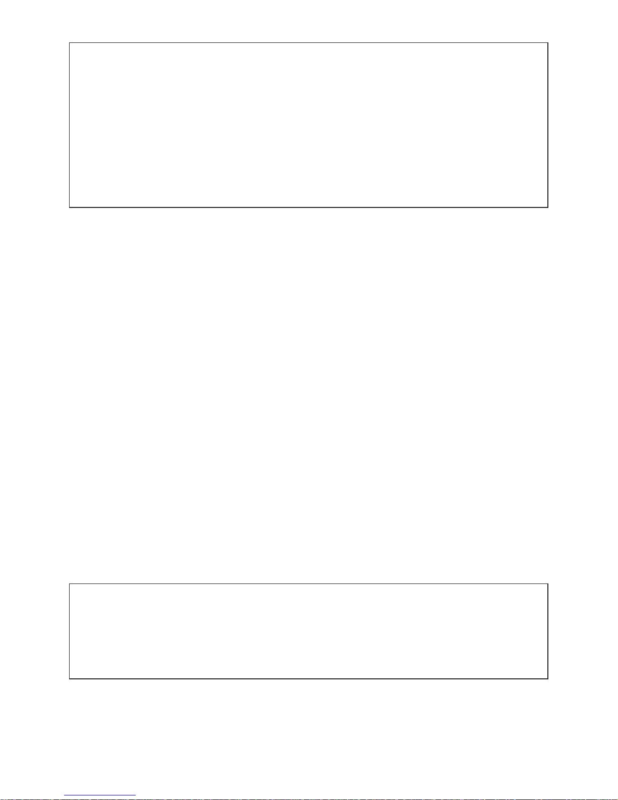
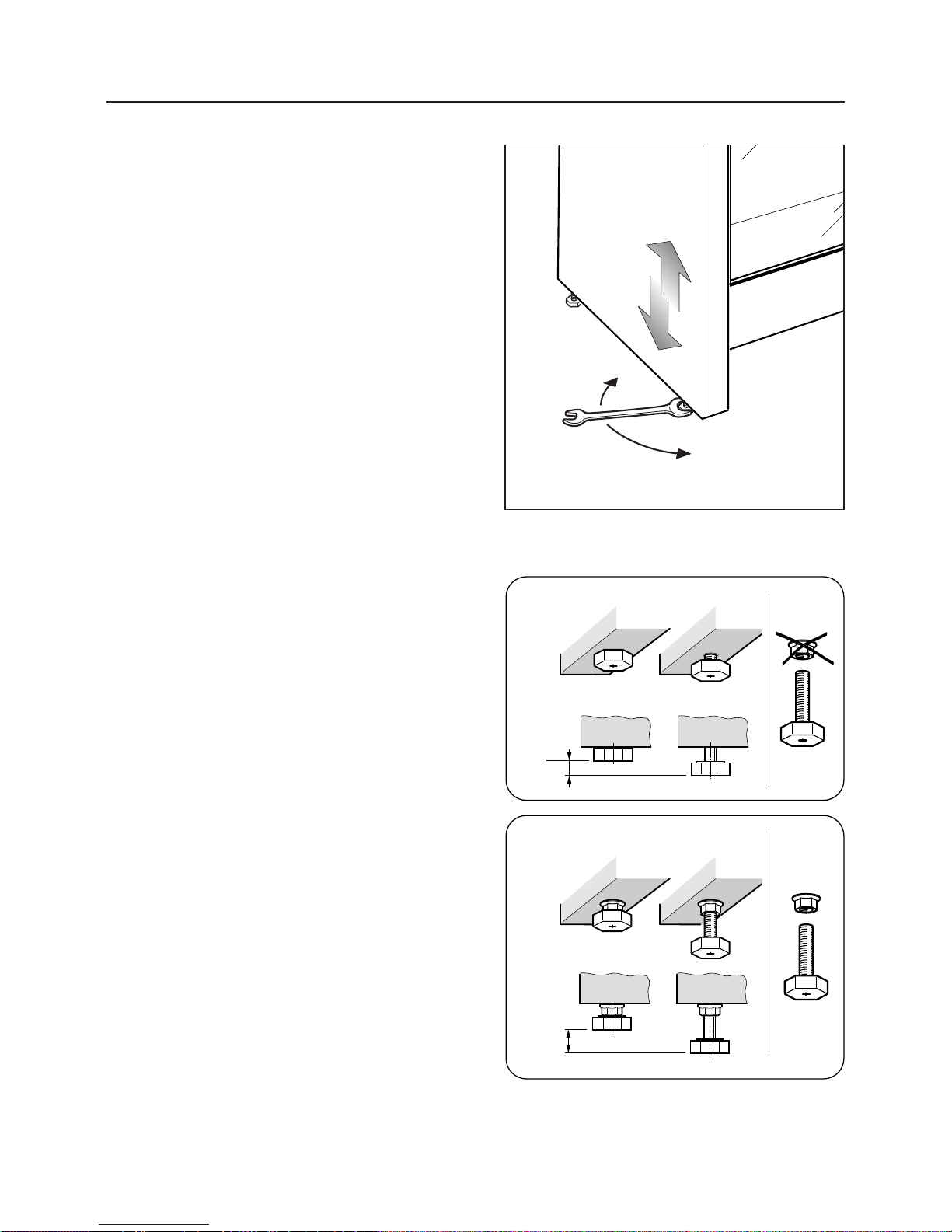
If the cooker is located on a
pedestal it is necessary to pro-
vide safety measures to prevent
falling out. Fig. 2.1b
Fig. 2.1a
"<129 &
"<129 &

9
The adjustable feet must be fitted
to the base of the cooker before
use.
Rest the rear of the cooker on a
piece of the polystyrene packag-
ing exposing the base for the fit-
ting of the feet.
Fit the 4 legs by screwing them
tight into the support base as
shown in picture 2.3.
!2C2996;4 A52 0<<82?
The cooker may be levelled by
screwing the lower ends of the feet
IN or OUT (fig. 2.4).
Fig. 2.2
Fig. 2.3
Fig. 2.4
6AA6;4 A52 .17B@A./92 322A .;1 92C2996;4 A52 0<<82? "<129 &

10
!2C2996;4 A52 0<<82? "<129 &
Fig. 2.5
+ 8 mm
+ 8
0
mm
+ 35 mm
Fig. 2.6a
Fig. 2.6b
The cooker is already fitted with four
levelling feet.
Level the cooker by screwing or
unscrewing the feet (Fig. 2.5).
Make sure you follow the instructions
in Figs. 2.6a and 2.6b.
Note: bolts are supplied with the
cooker in a separate kit.

11
+.?;6;4
When moving cooker to its final position $#$(& (fig. 2.9a - 2.9b).
Lift feet clear of floor (fig. 2.7a - 2.7b).
+.?;6;4
20.?23B991<;<A963AA520<<82? /F A521<<?5.;192D52;?.6@6;4A< A52 B=?645A
=<@6A6<; 364. /
"<C6;4 A52 0<<82? +.?;6;4
+52; ?.6@6;4 0<<82? A< B=?645A =<@6A6<; .9D.F@ 2;@B?2 AD< =2<=92 0.??F <BA A56@
:.;<2BC?2 A< =?2C2;A 1.:.42 A< A52 .17B@A./92 322A 364. /
Fig. 2.7a
Fig. 2.8a
Fig. 2.9a
Fig. 2.7b
Fig. 2.8b
Fig. 2.9b

12
We recommend a stability bracket is fitted to the cooker.
The type shown in fig. 2.10 can be purchased from most plumbers merchants and
do it yourself (D.I.Y.) shops.
Wall fixing Floor fixing
Bracket
Existing slot in
rear of cooker
Dotted line showing the position
of cooker when fixed
Dimension is in millimetres
3
Outline of cooker
backplate at the
engagement slot
Fig. 2.10
'A./696AF /?.082A "<129 &

13
We recommend a stability bracket is fitted to the cooker.
The type shown in fig. 2.11 can be purchased from most plumbers merchants and
do it yourself (D.I.Y.) shops.
Wall fixing Floor fixing
Bracket
Existing slot in
rear of cooker
Dotted line showing the position
of cooker when fixed
Dimension is in millimetres
3
Outline of cooker
backplate at the
engagement slot
Fig. 2.11
'A./696AF /?.082A "<129 &

14
%?<C6@6<; 3<? C2;A69.A6<;
– The appliance should be installed into a room or space with an air supply in accor-
dance with BS 5440-2: 2000.
– For rooms with a volume of less than 5 m3- permanent ventilation of 100 cm2free
area will be required.
– For rooms with a volume of between 5 m3and 10 m3a permanent ventilation of
50 cm2free area will be required unless the room has a door which opens directly
to the outside air in which case no permanent ventilation is required.
– For rooms with a volume greater than 10 m3- no permanent ventilation is required.
–#&24.?192@@<3?<<:@6G2.99?<<:@0<;A.6;6;4A52.==96.;02:B@A5.C216?20A
.002@@ A< A52 <BA@612 .6? C6. .; <=2;./92 D6;1<D <? 2>B6C.92;A
– Where there are other fuel burning appliances in the same room, BS 5440-2: 2000
should be consulted to determine the correct amount of free area ventilation require-
ments.
– The above requirements allow also for use of a gas oven and grill but if there are
other gas burning appliances in the same room, consult a qualified engineer.

15
.@ 6;@A.99.A6<;
"%$&(#(#$(
This appliance is supplied for use on NATURAL GAS or LPG (check the gas regula-
tion label attached on the appliance).
– Appliances supplied for use on NATURAL GAS: they are adjusted for this gas only
and cannot be used on any other gas (LPG) without modification. The appliances
are manufactured for conversion to LPG.
– Appliances supplied for use on LPG: they are adjusted for this gas only and cannot
be used on any other gas (NATURAL GAS) without modification. The appliances are
manufactured for conversion to NATURAL GAS.
If the NATURAL GAS/LPG conversion kit is not supplied with the appliance this kit can
be purchased by contacting the After-Sales Service.
;@A.99.A6<; @2?C602 ?24B9.A6<;@ );6A21 6;41<:
It is a legal requirement that all gas appliances are Installed & Serviced by a competent
person in accordance with the current editions of the following Standards & Regulations
or those regulations appropriate to the geographical region in which they are to be
installed:
– Gas Safety (Installation & Use) Regulations
– Building Regulations
– British Standards
– Regulations for Electrical Installation
Installation and service of any gas product must be made by a suitably qualified person
competent on the type of product being installed or serviced and holding a valid
certificate of competence for the work being carried out. Currently the proof of
competence is the Accredited Certification Scheme (ACS) or S/NVQ that has been
aligned to the ACS.
It is also a requirement that all businesses or self employed installers are members of a
class of person approved by the ealth and Safety Executive.
Failure to install the appliance correctly could invalidate any manufacturers warranty and
lead to prosecution under the above quoted regulation.

16
The installation of the gas appliance to Natural Gas or LP Gas must be carried out by
a suitably qualified and registered person. Installers shall take due account of the pro-
visions of the relevant British Standards Code of Practice, the Gas Safety Regulations
and the Building Standards (Scotland)(Consolidation) Regulations issued by the Scottish
Development Department.
;@A.99.A6<;A<#.AB?.9.@
Installation to Natural Gas must conform to the Code of Practice, etc.
The supply pressure for Natural Gas is 20 mbar.
The installation must conform to the relevant British Standards.
;@A.99.A6<;A<!%.@
When operating on Butane gas a supply pressure of 28-30 mbar is required. When
using Propane gas a supply pressure of 37 mbar is required.
The installation must conform to the relevant British Standards.
+.?;6;4 Only a suitably qualified and registered person, also with technical knowledge
of electricity should install the appliance. e should observe the Regulations and Codes
of Practice governing such installation of gas appliances.
Note: It is recommended that the gas connection to the appliance is installed with a
flexible connecting tube made to BS5386.
#<A2@
92E6/92 5<@2@ 0.; /2 B@21 D52?2 A52 @6A21 .:/62;A A2:=2?.AB?2 <3 A52 5<@2
1<2@;<A2E0221H(52@25<@2@:B@A/2:.;B3.0AB?216;.00<?1.;02D6A5
'=.?A.;1/2<3A520<??20A0<;@A?B0A6<;3<?A52AF=2<34.@/26;4B@21
.@5<@2@12@64;213<?;.AB?.94.@")'(#$(/2B@213<?@B==9F6;4!%4.@
!%4.@5<@2@0.;/2612;A63621/F.26A52?.?21/.;1<?@A?6=2<;A52?B//2?
<BA2?0<.A6;4<3A525<@2
(525<@2 @5<B91;<A/2 0?B@521 <?A?.==21 <? /26;0<;A.0A D6A5@5.?=<?
./?.@6C22142@
Using a suitable leak detection fluid solution (e.g. Rocol) check each gas connection
one at a time by brushing the solution over the connection.
The presence of bubbles will indicate a leak.
If there is a leak, tighten the fitting and then recheck for leaks.
"%$&(#(
< ;<A B@2 . ;.821 39.:2 A< A2@A 3<? 92.8@
.@ 0<;;20A6<;

17
.@0<;;20A6<; .A
The gas supply must use the nearest gas inlet pipe which is located at the left or the
right hand side at the rear of the appliance (figs. 3.1a, 3.1b).
The hose should also be connected in such away that it does not touch the floor.
To screw the connecting tube operate with two spanners (fig. 3.2).
The unused end inlet pipe must be closed with the plug interposing the gasket.
3A2?0<;;20A6;4A<A52:.6;@05208A5.AA520<B=96;4.?20<??20A9F@2.921B@6;4
@<.=F @<9BA6<; /BA ;2C2? . 39.:2
GB
Fig. 3.1a
Fig. 3.1b
Fig. 3.2
Left gas
inlet pipe
Right gas
inlet pipe
1/2” BSP (male)
1/2” BSP (male)
Left gas
inlet pipe Right gas
inlet pipe
Plug
Plug
"<129 &
"<129 &

18
:=<?A.;A =?2@0?6=A6<;@ 3<? 4.@ 0<;;20A6<;
700 mm
700 mm
Rear wall
Rear wall
Suggested area for
gas mains connection
Suggested area for
gas mains connection
200 mm
200 mm
Fig. 3.3a
700 mm
Rear wall
Suggested area for
gas mains connection
200 mm
Fig. 3.3b
"<129 &
"<129 &

19
<;C2?@6<; A< #.AB?.9 .@ <? A< !%
;720A<?@ ?2=9.02:2;A <3
A<= /B?;2?@
Every cooker is provided with a set of
injectors for the various types of gas.
Injectors not supplied can be obtained
from the After-Sales Service.
Select the injectors to be replaced
according to the table at page 21.
The nozzle diameters, expressed in
hundredths of a millimetre, are marked
on the body of each injector.
To replace the injectors proceed as fol-
lows:
– Remove the grids and extract the
burner bodies.
– Using a wrench, substitute the nozzle
injectors “J” (Figs. 3.4a, 3.4b, and
3.4c) with those most suitable for the
kind of gas for which it is to be used
(see “Table for the choice of the injec-
tors”).
(52 /B?;2?@ .?2 0<;@A?B0A21 6; @B05
. D.F @< .@ ;<A A< ?2>B6?2 A52 ?24B
9.A6<; <3 A52 =?6:.?F .6?
Fig. 3.4b
Fig. 3.4a
Auxiliary and
Semi-rapid
burner
Triple-ring
burner
DUAL burner
Injector for inner crown
Injectors for
outer crowns
Fig. 3.4c

20
17B@A6;4<3A52:6;6:B:<3
A52A<=/B?;2?@
In the minimum position the flame
must have a length of about 4 mm and
must remain lit even with a quick turn
from the maximum position to that of
minimum.
The flame adjustment is done in the
following way:
BE696.?F @2:6?.=61 .;1 A?6=92
?6;4 /B?;2?@
– Light the burner
– Set the gas valve to position
– Remove the knob
– Using a screwdriver turn the screw F
until the correct setting is obtained
(fig. 3.5).
;@612 0?<D; <3 )! /B?;2?
– Light the DUAL burner
– Set the gas valve to position
– Remove the knob
– Using a screwdriver turn the screw
until the correct setting is obtained
(fig. 3.6).
$BA@612 0?<D;@ <3 )! /B?;2?
– Light the DUAL burner
– Set the gas valve to position
– Remove the knob
– Using a screwdriver turn the screw
until the correct setting is obtained
(fig. 3.6).
#<?:.99F 3<? !% A645A2; B= A52
?24B9.A6<; @0?2D
Fig. 3.6
F
Fig. 3.5
This manual suits for next models
1
Table of contents
Other Caple Range manuals
Popular Range manuals by other brands

Kenmore
Kenmore 79041093100 installation instructions

Thermador
Thermador Professional PRO-HARMONY PRG30 Care and use manual

Summit
Summit PRO201 Owner's manual and installation instructions

Frigidaire
Frigidaire GLEFZ384HCA Use & care manual

Whirlpool
Whirlpool 8177945 manual

Commercial Pro
Commercial Pro CIN-10 manual