CaptiveAire TANK User manual

Model TANK Fire Suppression Extinguishing System
Installation, Operation, and Maintenance Manual
TANK Fire Suppression Extinguishing System Typical Hood End Cabinet Installation
RECEIVING AND INSPECTION
Check for any signs of damage upon receipt, and if found, report it immediately to the carrier.
Check that all items are accounted for and free of damage.
WARNING!!
The TANK Fire Suppression extinguishing system unit is to be installed, inspected, recharged
and maintained in accordance with NFPA 17A, NFPA 96, and the National Fire Code of Canada
as applicable.
Installation and maintenance of the TANK Fire Suppression extinguishing system must be
performed in accordance with this manual by a factory trained and authorized distributor.
Improper installation poses serious risk of injury due to electric shock and other potential
hazards. Read this manual thoroughly before installing or servicing this equipment. ALWAYS
disconnect power prior to working on equipment.
Save these instructions. This document is the property of the owner of this equipment and is required
for future maintenance. Leave this document with the owner when installation or service is complete.
Part No. A0029342
August 2021 Rev 13

2

3
WARRANTY ............................................................................. 4
Certifications and Approvals ................................................. 4
System Overview .................................................................. 4
COMPONENTS ....................................................................... 5
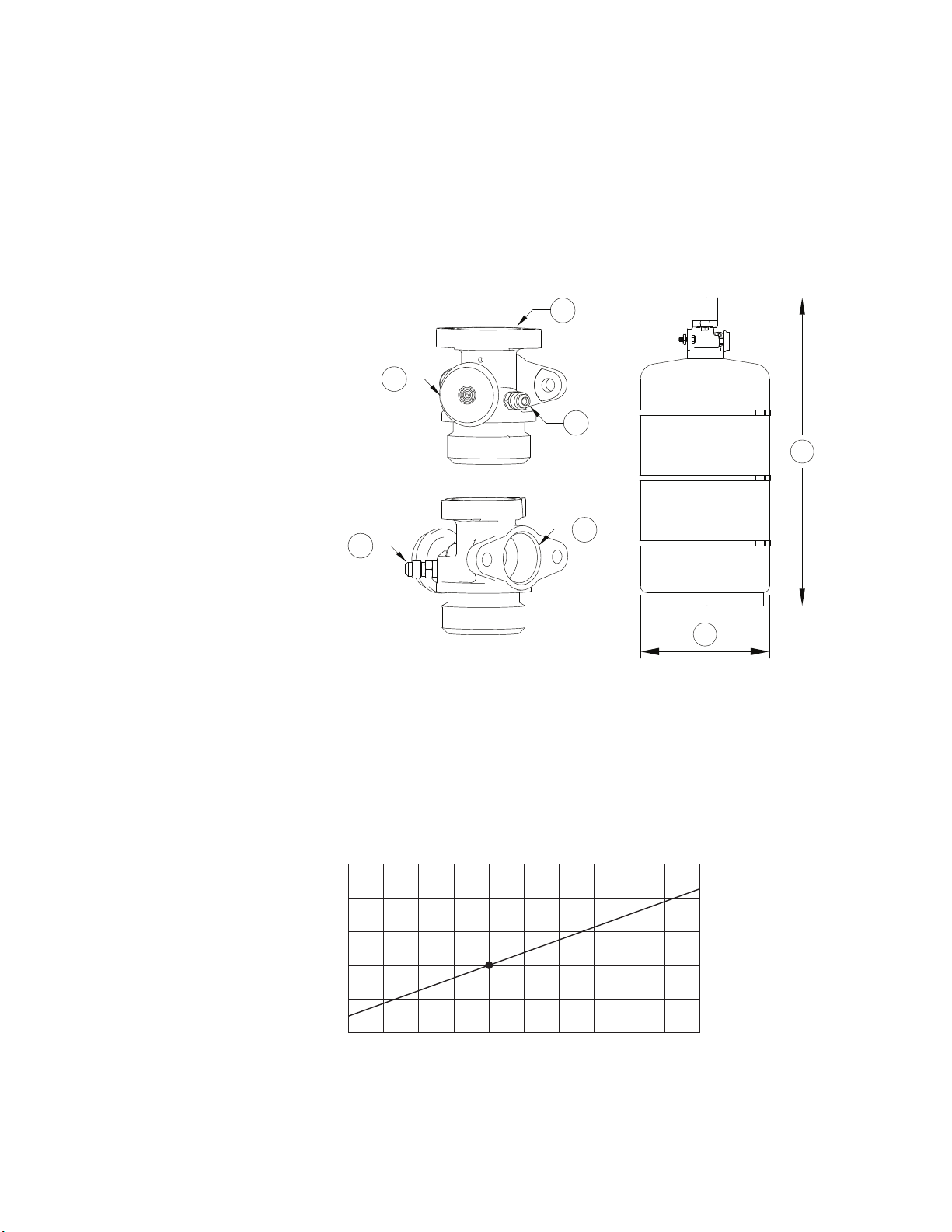
Cylinder Assembly ................................................................ 6
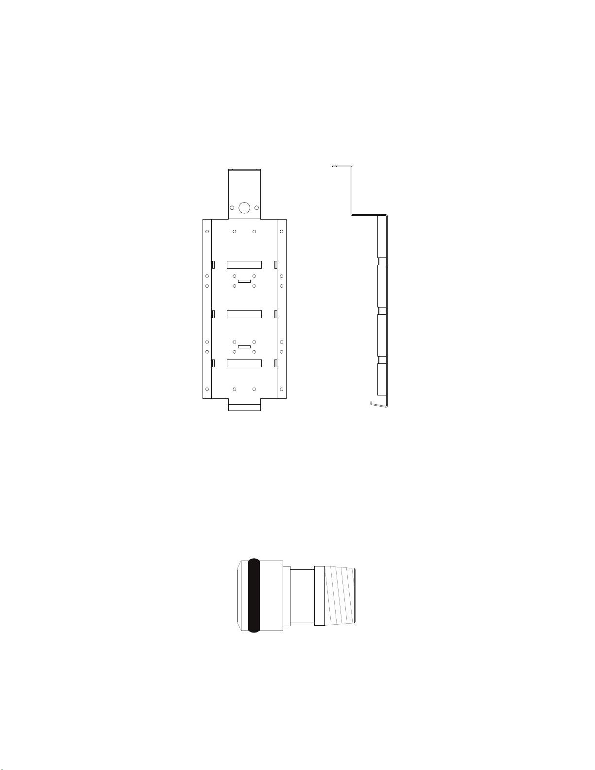
Cylinder and Actuator Bracket .............................................. 7
Discharge Adapter ................................................................ 7
Nozzles ................................................................................. 8
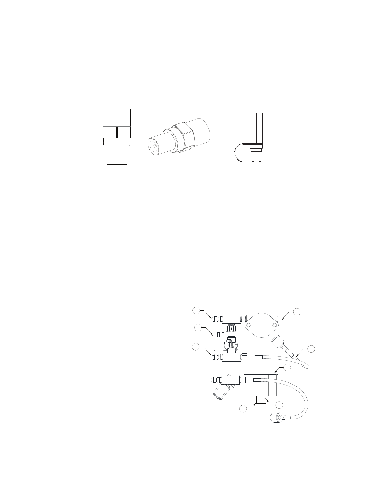
Primary Actuator Kit (PAK) ................................................... 8
Secondary Valve Actuator (SVA) and Hose ......................... 9
Supervisory Pressure Switch ................................................ 9
Gas Shut-Off Valves ........................................................... 10
Electric Remote Manual Release ....................................... 10
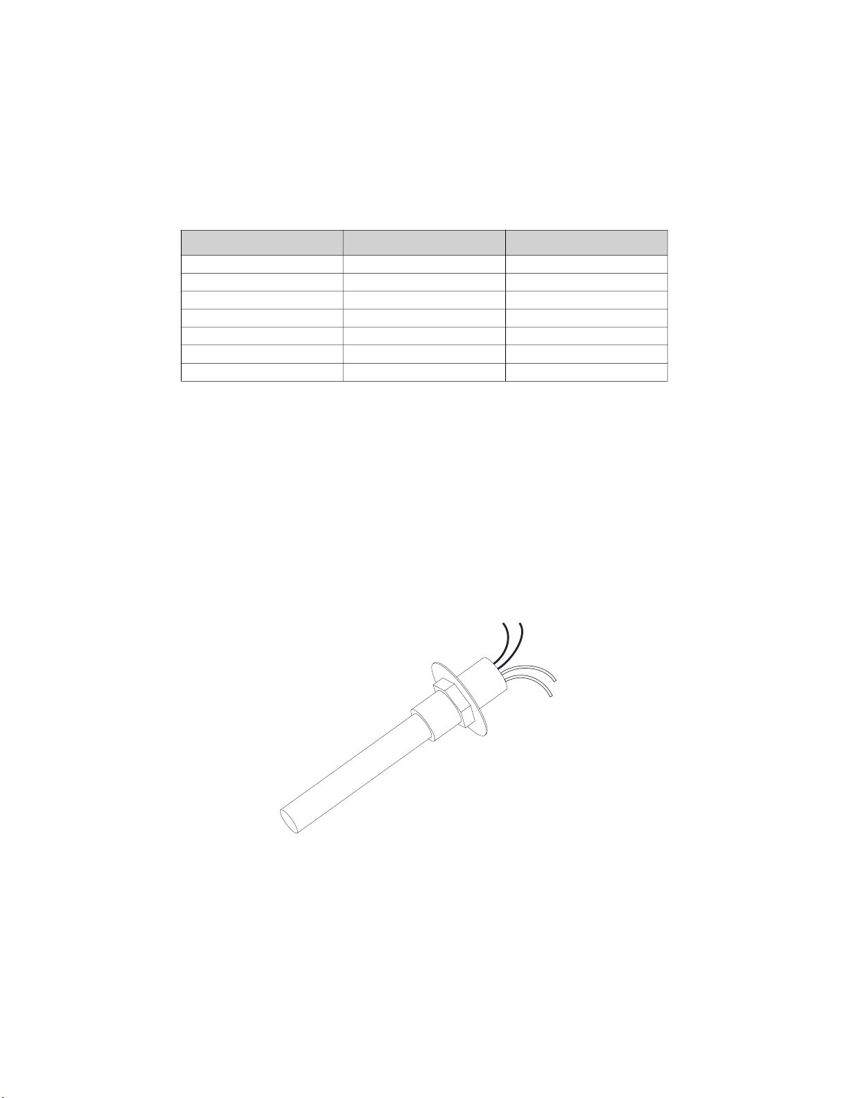
Firestat (Heat) Detector ...................................................... 10
INSTALLATION ...................................................................... 11
Cylinders ............................................................................. 11
Primary and Secondary Actuator Installation ...................... 12
Primary Actuator Kit (PAK) ................................................. 12
Secondary Valve Actuator .................................................. 13
Supervisory Pressure Switch .............................................. 14
Duct and Plenum Protection ............................................... 15
Plenum Protection ........................................................... 15
Duct Protection ................................................................ 16
Ventilation Exhaust and Dampers ...................................... 18
Electrostatic Precipitators (ESP) ......................................... 18
Appliance Protection ........................................................... 19
Overlapping Appliance Protection ................................... 19
Appliance Coverage ........................................................... 20
Coverage Exceptions ...................................................... 21
Overlapping Protection .................................................... 23
Overlapping Coverage - Group Protection ...................... 23
Upright Broiler/Salamander Protection ............................ 26
Appliance with Shelf ........................................................ 27
Wok Protection ................................................................ 28
Large Wok Protection ...................................................... 29
Appliance with Upright Obstruction ................................. 30
Appliance with Overhead Salamander ............................ 31
Pizza Ovens .................................................................... 32
Agent Distribution Piping .................................................... 34
Single Cylinder Nozzle and Piping Parameters ............... 35
Dual Cylinder Nozzle and Piping Parameters ................. 35
Nozzle Installation ........................................................... 36
Gas Shut-Off Valves ........................................................ 37
Fire Protection System Firestat .......................................... 38
Non-Solid Fuel Appliances (Rated 450°F) ....................... 38
Non-Solid Fuel Appliances (Rated 600°F) ....................... 38
Solid Fuel Appliances (Rated 700°F) .............................. 38
Hood Riser Sensor Replacement ....................................... 40
Fire Protection Manual Actuation Device ............................ 41
Trouble Input Wiring ........................................................... 41
Battery Backup ................................................................... 42
Power Supply Adjustment ................................................... 42
Fire Protection System Printed Circuit Board .................. 43
ELECTRICAL ......................................................................... 46
Wire Ampacity Rating ......................................................... 47
Distance Limitations ............................................................ 47
Fire Alarm Contacts ............................................................ 47
Fire Group ........................................................................... 48
Fire Protection System Supervised Loops .......................... 49
OPERATION .......................................................................... 50
Test Mode Overview ........................................................... 50
Reset Overview .................................................................. 51
TROUBLESHOOTING ........................................................... 53
Appliance Shutdown in Fault Conditions ............................ 54
Local Alarm Muting .......................................................... 54
Test Mode ....................................................................... 54
Supervised Loop Wiring Troubleshooting ........................... 55
DIP Switch Settings ......................................................... 56
Typical DIP Switch Arrangement ..................................... 57
INSPECTION AND TEST ...................................................... 58
Start-up/Test Procedure ..................................................... 58
Preparing System for Test ............................................... 58
Connecting Service Test Tank to the System ................. 58
Test Procedure ................................................................ 59
Disconnecting Service Tank/Re-arming System ............. 60
MAINTENANCE ..................................................................... 61
Every Month (System Owner) ............................................ 61
Every Six Months (Authorized Distributor) .......................... 62
Every Twelve-Years ........................................................... 62
Agent Cylinders ............................................................... 62
Actuation Hoses .............................................................. 62
Conditional Maintenance .................................................... 63
Replacing A Primary Actuation Kit .................................. 63
Replacing A Secondary Valve Actuator .......................... 63
Mobile Kitchen Decommissioning/Commissioning .......... 64
POST-DISCHARGE MAINTENANCE ................................... 65
General Information ............................................................ 65
Appliance Cleanup ............................................................. 65
Cleaning Distribution System ............................................. 65
Cleaning Nozzles ................................................................ 65
Flushing the Distribution Pipe Network ............................... 66
Flushing Procedure with Spare/Test Cylinder .................... 66
Flushing Procedure with an External Water Supply ........... 67
Cylinder Maintenance ......................................................... 67
Removing a Cylinder .......................................................... 68
Depressurizing a Cylinder ............................................... 69
Installing a Cylinder ......................................................... 70
Rechecking the System ................................................... 70
TANK FIRE SUPPRESSION SYSTEM PARTS .................... 71
Start-Up and Maintenance Documentation ........................ 72
Job Information ................................................................... 72
Table of Contents

4
WARRANTY
Model TANK Fire Suppression extinguishing system is warranted to be free from defects in materials and
workmanship, under normal use and service, for a period of 60-months from date of shipment. Warranty
does not cover consumable products such as batteries and nitrogen. This warranty is null and void if:
1. The system is not installed by a factory trained installer per the MANUFACTURER’S installation
instructions shipped with the product.
2. The equipment is not installed in accordance with Federal, State, Local codes, and regulations.
3. The system is misused or neglected, or not maintained per the MANUFACTURER’S maintenance
instructions.
4. The system is not installed and operated within the limitations set forth in this manual.
5. The invoice is not paid within the terms of the sales agreement.
The MANUFACTURER shall not be liable for incidental and consequential losses and damages potentially
attributable to malfunctioning equipment. Should any part of the equipment prove to be defective in
material or workmanship within the 60-month warranty period, upon examination by the
MANUFACTURER, such part will be repaired or replaced by MANUFACTURER at no charge. The BUYER
shall pay all labor costs incurred in connection with such repair or replacement. Equipment shall not be
returned without MANUFACTURER’S prior authorization, and all returned equipment shall be shipped by
the BUYER, freight prepaid to a destination determined by the MANUFACTURER.
NOTE: To receive warranty coverage for this product, copy and print out the “Start-Up and
Maintenance Documentation” on page 72. Fill in all required information. Fax the page to
1-919-516-8710 or call 1-866-784-6900 for emailing information.
Certifications and Approvals
The Tank Fire Suppression system is ETL Listed in accordance with ANSI/CAN/UL/ULC 300, ULCORD-
C1254.6.
The microprocessor-based control board is ETL Listed to UL Standard 864 and CAN/ULC-S527-11.
The Tank Fire Suppression system is acceptable for use in New York City, and is approved per FDNY
COA #5870.
System Overview
The Tank Fire Suppression extinguishing system provides fire protection for commercial cooking
appliances and ventilation. The Tank Fire Suppression extinguishing system is electrically released via a
24V DC solenoid valve. Extinguishing system units with electrical detection, activation, and control require
the use of a Listed Control Panel, which has been found acceptable for releasing device service and which
is compatible with the electrical actuators used on the extinguishing system. In addition, all electrical
detectors, notification devices, and pull stations are required to be Listed and compatible with the Control
Panel.

5
COMPONENTS
The following section lists the major components used in the TANK Fire Suppression extinguishing
system.
Figure 1 - Shipping/Test View
Figure 2 - Exploded View
NOTE: Tanks should never be filled in the field.
1. Unit is shown in Shipping/Test
Position
2. Tank Straps
3. Tank Mounting Bracket
(Secured to cabinet with rivets)
4. Cylinder Tanks (Up to four
tanks may be installed
depending on cabinet size.)
1
2
3
4
2
1. Tank Mounting Brackets
2. Secondary Supervisory Pressure
Switch (Optional)
3. Secondary Cylinder (Optional)
4. Primary Cylinder
5. Supervisory Pressure Switch
6. Primary Actuator Kit
7. Secondary Actuator Hose (Optional)
8. Secondary Valve Actuator (Optional)
9. Primary Valve with Siphon Tube
10. Secondary Valve with Siphon Tube
(Optional)
Tank straps not shown.
1
3
7
2
8
4
5
10
6
9

6
Cylinder Assembly
The TANK Fire Suppression cylinder assembly (p/n 87-300001-001) uses a mild steel cylinder, conforming
to 4BW250 DOT & 4BWM-17 TC specifications, and a nickel-plated brass valve with pressure indicator
gauge. Each valve includes a Schrader port for connection to the primary actuator hose (for primary
cylinders) or the supervisory pressure switch (optional for secondary cylinders).
Each cylinder assembly is factory-filled with TANK liquid fire suppressant and pressurized to 200 PSIG
(1379 kPA) at 70°F (21°C). Each cylinder supports up to 5 nozzles for a total of 20 flow points.
Figure 3 - Cylinder Tank Details
The pressure of a cylinder will vary with the ambient temperature, as detailed in Table 1. The gauge
indicator (shown in Figure 3) should be in the acceptable ‘green’ range for a cylinder that is properly
pressurized and within the listed operating temperature range. For a cylinder at the lowest listed operating
temperature of 32°F (0°C), the pressure gauge should read approximately 175 psig (the lower end of the
green range). For a cylinder at the highest listed operating temperature of 130°F (54.4°C), the pressure
gauge should read approximately 225 psig (the upper end of the green range).
Table 1 - Cylinder Temperature Vs Pressure
1. Valve Actuation Interface
2. Schrader Valve
3. Pressure Gauge
4. Discharge Outlet
A. Tank to Actuator Distance =
23-1/4”
B. Tank Diameter = 10”
A
B
1
2
3
4
2
225
(1551 kPA)
215
(1482 kPA)
205
(1413 kPA)
195
(1344 kPA)
185
(1275 kPA)
175
(1206 kPA)
30
(-1)
40
(4)
50
(10)
60
(15.6)
70
(21)
80
(27)
90
(32)
100
(38)
110
(43.3)
120
(49)
130
(54.4)
Temperature °F (°C)
Pressure PSIG (kPa)

7
Cylinder and Actuator Bracket
Each cylinder assembly is secured to a factory-installed cylinder bracket in the cabinet (p/n TFS-
UCTANKBRACKET). The cylinder is secured to the cylinder bracket via three (3) stainless steel straps.
The cylinder bracket also includes a platform for securing a primary actuator kit or secondary valve
actuator during shipping and maintenance procedures.
Figure 4 - Cylinder and Actuator Bracket
Discharge Adapter
The discharge adapter (p/n WK-283952-000) is used to connect the TANK Fire Suppression cylinder valve
outlet to the agent distribution pipe network. The 1/2-inch NPT internal thread of the discharge adapter
outlet is connected to the supply line via an elbow and adapter.
The discharge adapter uses an O-ring (p/n WK-108019-000) at the valve port to eliminate leaks during
discharge.
Figure 5 - Discharge Adapter

8
Nozzles
The nozzle (p/n 3070-3/8H-SS10) is a 4 flow nozzle and is used for plenum, duct, and dedicated appliance
coverage (e.g., salamanders, upright broilers, chain broilers, and appliance with upright obstructions). The
nozzles include a cap (p/n 3074-1-1). The cap prevents contamination from entering the pipe network and
is designed to pop-off upon system discharge, allowing the agent to flow to the protected hazard area.
Refer to “Duct and Plenum Protection” on page 15.
Figure 6 - Fire System Nozzle
Primary Actuator Kit (PAK)
The Primary Actuator Kit (PAK) (p/n 87-300030-001) is installed on each primary cylinder assembly to
pneumatically open the cylinder valve and provide actuation pressure for up to three secondary valve
actuators.
The PAK consists of a pneumatic actuator, 24V DC solenoid valve, check valve, primary actuator hose,
and associated fittings.
Upon automatic or manual system actuation, the control panel sends a momentary 24V DC release signal,
opening the PAK solenoid. Pressure from the primary cylinder is passed through the solenoid and check
valve, into the primary actuator (actuating the primary cylinder), and into the interconnected secondary
valve actuators (actuating the secondary cylinders).
The primary actuator has a 1/8” NPT inlet port for connection to the primary system cylinder, and a 1/8”
NPT outlet port for connection to the secondary cylinder actuation line or actuation plug for single cylinder
system. The primary actuator includes a piston with a spring-loaded locking pin which locks the piston in
the discharge position, ensuring complete discharge of the cylinder contents.
Figure 7 - Primary Actuator Kit
NOTE: The primary supervisory pressure switch is standard on primary tanks. Secondary
supervisory pressure switches are optional on secondary tanks.
1. Schrader Service Port
2. Primary Actuator Hose
(Stainless Steel)
3. Solenoid Valve
4. Supervisory Pressure
Switch Connection
5. Primary Actuator
6. Locking Pin
7. Piston
5
1
2
1
3
4
6
7

9
Secondary Valve Actuator (SVA) and Hose
A Secondary Valve Actuator (SVA) (p/n 87-120042-001) is installed on each secondary cylinder assembly
to pneumatically open the cylinder valve(s). The SVA has 1/8” NPT inlet and outlet ports for connection to
the system actuation line via the SVA hose. All secondary hoses require a 1” minimum bend radius. The
SVA includes a spring-loaded locking pin that locks the actuator piston in the discharge position, ensuring
complete discharge of the cylinder contents.
Figure 8 - Secondary Valve Actuator
Supervisory Pressure Switch
The primary and (optional) secondary supervisory pressure switch (p/n 87-300040-001) are preset to
alarm at a cylinder pressure of ~10% below the lowest operating system pressure of 175 psig (pressure at
the lowest listed operation temperature of 32°F). The supervisory pressure switch uses a diaphragm
sensor to detect pressure changes. At the predetermined set point, the unit actuates a SPDT snap-acting
switch, converting a pressure signal into an electrical signal. The supervisory pressure switch can be used
on primary and/or secondary cylinders. For primary cylinders, the pressure switch is mounted on the
primary actuator kit. For secondary cylinders, the pressure switch is mounted on the Schrader fitting
installed on the cylinder valve.
Figure 9 - Supervisory Pressure Switch
1. Actuation Line Plug
2. Locking Pin
3. Piston
4. Secondary Valve Actuator Hose
• 7.5” hose option (p/n 87-120045-001)
• 24” hose option (p/n 87-120045-002)
• 60” hose option (p/n 87-120045-003)
32
1
4
1. Supervisory Pressure Switch
(Primary)
2. Wrench Flats
3. Secondary Supervisory
Pressure Switch (Optional)
4. Schrader Valve Port
4
1
2
2
3

10
Gas Shut-Off Valves
Electric gas shut-off valves are used to shut down the flow of fuel gas to the kitchen appliances upon
actuation of the TANK Fire Suppression system. An energized solenoid is used to hold the gas valve in the
open position. The solenoid closes the valve when de-energized via the output relay of the control panel.
The gas valves are available in 120V AC and 24V DC, ranging from 3/4” to 3” pipe sizes (Table 2).
Electric Remote Manual Release
An electrically operated manual release that is listed must be used with the TANK Fire Suppression
extinguishing system. The electric remote manual release is used to actuate the TANK Fire Suppression
extinguishing system manually and must be properly located and supervised in accordance with NFPA
17A and NFPA 96.
Firestat (Heat) Detector
The Firestat (Fenwal Detect-a-Fire) is a listed electric thermal detector available in a variety of temperature
settings and used to actuate the TANK Fire Suppression extinguishing system automatically. When a
Firestat senses a temperature higher than its setpoint, the Firestat contacts will close and energize the
TANK Fire Suppression system via the control panel.
Figure 10 - Firestat
Table 2 - Electric Gas Valves
Size P/N (ASCO) 120V AC P/N (ASCO) 24V AC
3/4” 8214235 8214G236-24VDC
1” 8214250 8214G251-24VDC
1-1/4” 8214265 8214G266-24VDC
1-1/2” 8214275 8214G276-24VDC
2” 8214280 8214G281-24VDC
2-1/2” 8214290 -
3” 8214240 -

11
INSTALLATION
The extinguishing system consists of pressurized agent storage cylinders, agent distribution piping, valve
actuators, supervisory pressure switches, and agent discharge nozzles. All primary components and
piping are factory-installed. Systems may be comprised of single or multiple cylinders depending on the
size and configuration of the protected hazards.
Cylinders can be piped independently, or manifolded. On two-cylinder systems, the cylinders will be in a
manifold configuration. Refer to Figure 34 on page 34 for a two-cylinder system example. On three-
cylinder systems, two cylinders will be in a manifold configuration and one independent. On four-cylinder
systems, there will be two separate manifolds.
In a fire condition or upon manual actuation, the solenoid valve is opened, allowing pressure from the
primary cylinder to flow to the primary and secondary cylinder valve actuators, opening the cylinder valves
and discharging liquid fire suppressant to the protected hazard areas.
Figure 11 - Cylinder Assemblies
Cylinders
Cylinders are typically factory-installed, pressurized, and may be located anywhere within the hood end
cabinet. Additional cylinders may be field installed, as needed, in the additional hood end or wall mount
cabinet. The following examples show a dual cylinder system mounted to the right of the hood control unit.
Each cylinder assembly is secured to a factory-installed cylinder bracket in the hood end cabinet. The
cylinder is secured to the cylinder bracket via three (3) stainless steel straps.
Figure 12 - Dual Cylinder Mounted in Cabinet
WARNING!
System must be installed in conditioned space between 32°F and 130°F.
12
12
1. Primary Cylinder Assembly
2. Secondary Cylinder Assembly (Optional)
Right side cabinet mount shown.

12
Primary and Secondary Actuator Installation
Figure 13 - PAK in Ship/Test and Installed Positions
Primary Actuator Kit (PAK)
Figure 14 - Actuator Valve Set Position
The primary actuator kit is mounted to the primary cylinder
bracket during shipment and when testing the system. With the
cylinders securely mounted and connected to the system
piping, the primary actuator kit can be installed onto the
primary cylinder for the final setup.
1. Remove the valve protection plate and nuts. Retain the
mounting bolts for installation of the PAK.
2. Ensure the primary actuator piston is in the set position.
3. Loosen the PAK shipping bolts from the top of the bracket,
slide the unit back and lower it into position on the valve
actuation flange.
4. Insert the mounting bolts through the bottom of the valve
flange into the PAK mounting holes and tighten securely.
5. Connect the primary actuator hose to the Schrader valve
port on the primary cylinder valve. The primary hose
requires a 1.5” minimum bend radius.
WARNING!
Do not complete PAK or secondary valve actuator installation until system test and
commissioning are complete. The cylinder bracket includes a platform for securing a primary
actuator kit or secondary valve actuator during shipping and maintenance procedures. The
system actuators must be in the ship/test position for all commissioning and test procedures.
Testing with actuators in place will result in discharge of the agent cylinders.
Refer to “Start-up/Test Procedure” on page 58 for the testing and commissioning procedure.
1. Shipping Bolts
2. Nut
3. Valve Protection Plate
4. Mounting Bolts
5. Primary Actuator Kit (In Transport Position)
6. Supervisory Pressure Switch
Ship/Test Position Installed Position
5
1
2
3
4
6

13
Secondary Valve Actuator
With the cylinders securely mounted and connected to the system piping, the secondary valve actuators
(SVA) can be installed onto each of the secondary cylinder(s).
1. Remove the valve protection plate and nuts. Retain the mounting bolts for installation of the SVA.
2. Loosen the SVA shipping bolts from the top of the bracket, slide the unit back and lower it into position
on the valve actuation flange.
3. Insert the mounting bolts through the bottom of the valve flange into the SVA mounting holes and
tighten securely.
4. Ensure the secondary actuator hose is securely connected to the primary actuator output port and
SVA input port.
Key Limitations
• Refer to “Secondary Valve Actuator (SVA) and Hose” on page 9 for secondary hose information.
• Secondary actuator hose(s) require 1” minimum bend radius.
• Maximum number of secondary valve actuators operating from the primary actuator unit is three (3).
WARNING!
Installation of the primary actuator hose is the FINAL step performed.
Connecting this hose earlier may result in accidental system discharge. Refer to “Start-up/Test
Procedure” on page 58 for the testing and commissioning procedure.
When inspecting the primary actuator hose, replace O-ring (p/n 19020).
The primary and secondary actuation hoses cannot be interchanged. The primary actuation hose
must be used with the PAK.
WARNING!
The Valve Protection Plate must remain on the valve actuation port until the valve actuator is
installed.
The primary and secondary actuation hoses cannot be interchanged. The secondary actuation
hose (7", 24" or 60" length) must be used with secondary valve actuators.

14
Supervisory Pressure Switch
A supervisory pressure switch will always be located on the primary cylinder by the Primary Actuator Kit
(PAK). For secondary cylinders, this is an optional component that may be added on. For primary
cylinders, the pressure switch is mounted on the primary actuator kit. For all secondary cylinders, the
pressure switch is mounted on the Schrader fitting on the cylinder valve.
1. Remove cap from applicable Schrader fitting.
2. Thread the switch onto the Schrader using the brass wrench flats only.
Figure 15 - Supervisory Pressure Switch Installation
NOTE: Pressure switches do not contain any field replaceable parts. Refer to applicable control
panel manual for wiring of the supervisory pressure switch. Wire in accordance with local and
national electrical codes.
The electrical rating is rated to 5A resistive and 3A inductive at 30V DC; gold flashing over silver contact for
loads down to 1mA at 24V DC.
Supervisory pressure switches are connected in series to the control panel supervisory input.
WARNING!
Proof pressure (*) limits stated on the nameplate must never be exceeded, even by surges in the
system. Occasional operation of unit up to proof pressure is acceptable (e.g., start-up, testing).
Continuous operation should not exceed the designated over range pressure (**).
*Proof pressure - the maximum pressure to which a pressure sensor may be occasionally
subjected, which causes no permanent damage (e.g., start-up, testing).
**Over Range Pressure - the maximum pressure to which a pressure sensor may be continuously
subjected without causing damage and maintaining set point repeatability.
WARNING!
Disconnect all supply circuits before wiring pressure switch. Electrical ratings stated in literature
and on nameplate must not be exceeded - overload on a switch can cause failure on the first cycle.
Wiring Color Code
Red
Black
White
Terminals
NO (NC under Pressure)
NC (NO under Pressure)
Com
12
4
3
1. Supervisory Pressure Switch (Primary)
2. Wrench Flats
3. Optional Secondary Supervisory Pressure
Switch
4. Schrader Valve Port

15
Duct and Plenum Protection
The TANK Fire Suppression extinguishing system for duct and plenum coverage can be provided by
independent fire suppression tanks and piping or integrated with the fire suppression tanks and piping
used for protection of the appliances. Max of 5 nozzles per TANK for duct and plenum coverage only.
Plenum Protection
The nozzle (p/n 3070-3/8H-SS10) is used to protect plenum areas in both single bank and V-bank plenum
configurations. The nozzle will protect up to a 4' wide x 10' long plenum section. For larger plenum areas,
additional nozzles are added as required, with each nozzle protecting no more than a 4' wide by 10' long
plenum section. Nozzles may be installed pointing in the same direction, and/or at opposite ends of the
plenum, pointing toward each other. The nozzles must not be installed back-to-back when protecting
plenum areas. When positioned at the end of the plenum, nozzles must be installed from 0 to 6" into
plenum.
If the riser is not centered on the plenum, the plenum nozzle is placed on the side of the plenum closest to
the riser.
The nozzle locations for plenum protection are shown in Figure 16 and Figure 17.
Figure 16 - Single Bank Filter Plenum
*Isolated Plenum Place for Clarity
TOP VIEW
*Isolated Plenum Place for Clarity
Plenum
Nozzle
4' Max
Plenum
Nozzle
SIDE VIEW
4' Max
10' Max
0-6"
Height
Filter

16
Figure 17 - Dual V-Bank Filter Plenum
Duct Protection
The nozzle (p/n 3070-3/8H-SS10) is used for the protection of exhaust ductwork and can protect any duct
cross-section type (e.g. round, square, or rectangular). A sufficient quantity of nozzles must be provided to
ensure that no single nozzle coverage exceeds 75" in perimeter.
A single nozzle will protect a duct up to 75” perimeter (18” nominal diameter) and unlimited length. Two
nozzles are required for protection of 75-150” perimeter and unlimited length. A minimum of 3 nozzles is
required for protection of ducts exceeding 150" perimeter (36” nominal diameter) and unlimited length.
When using multiple nozzles (modular protection), the coverage area for each nozzle must not exceed 75"
perimeter.
Figure 18 - Nozzle Duct Protection
*Isolated Plenum Place for Clarity
TOP VIEW
*Isolated Plenum Place for Clarity
SIDE VIEW
4' Max
10' Max
0-6"
Plenum
Nozzle
Plenum
Nozzle
4' Max
Height
Filter
Filter
Plenum
Nozzle
2
1
2
1
3
4
1. Duct
2. Hood
3. Single Nozzle
4. Dual Nozzle

17
Nozzles must be installed from 0" to 6" into the protected area of the duct. When more than one nozzle is
required (modular protection), each nozzle must be located at the center of its protected module area.
Additional nozzles are not required for changes in direction*. Duct obstructions and common ductwork
must be protected in accordance with this manual, NFPA 17A and NFPA 96.
The nozzle location and aim for duct protection are shown in Figure 19 and Figure 20.
*When a change in direction occurs less than 6" from the duct entrance, the nozzle must be aimed as
shown in Figure 19 and Figure 20.
Figure 19 - Single Nozzle Placement (0-75” Perimeter Duct)
• Duct perimeter up to and including 75” (1270mm).
• To determine the perimeter: 2(A) + 2(B) = 75” (1905 mm).
1. Nozzle
2. Horizontal Duct Centerline (CL)
3. Aim Point
4. Vertical Duct Centerline (CL)
5. Duct Entrance
A. Rectangular Duct Width
B. Rectangular Duct Length
B
A
C
LC
L
C
L
1
4
3
2
1
18” Nom.
(457mm)
12.5”
(318mm)
Max
0-6”
(0-152mm) 2-4”
(51-102mm)
Square Duct Round Duct Rectangular Duct
5
Vertical Duct Vertical/Horizontal Duct

18
Figure 20 - Dual Nozzle Placement (75-150” Perimeter Duct)
Ventilation Exhaust and Dampers
The TANK Fire Suppression extinguishing system can be used with the exhaust fan either on or off when
the system is discharged. It is recommended that the exhaust fan remain on at the time of discharge to aid
in the removal of smoke, gases, and other airborne materials from the hazard area in the event of a fire. If
the Authority Having Jurisdiction (AHJ) requires that the damper closes in the event of a fire system
discharge, the system designer shall provide for protection downstream of the damper in compliance with
NFPA 96, local codes, and/or as approved by the AHJ.
Electrostatic Precipitators (ESP)
An Electrostatic Precipitator (ESP) is designed to remove smoke and other airborne contaminants from the
air flowing through the exhaust ductwork as a means of pollution control. Exhaust ductwork using ESPs
requires nozzle(s) (p/n 3070-3/8H-SS10) upstream, before the ESP. Distribution piping to the nozzles must
not interfere with the function of the ESP unit.
A Pollution Control Unit (PCU) and/or Electrostatic Precipitator (ESP) covered with this fire system can
utilize up to 12 nozzles per tank.
1. Nozzle
2. Vertical Duct Centerline (CL)
3. Aim Point
4. Horizontal Duct Centerline (CL)
5. Duct Entrance
A. 1/4 of dimension X
B. 1/2 of dimension X
C. 1/4 of Duct Diameter
D. 1/2 of Duct Diameter
L
CL
CL
CL
C
L
CL
C
L
CL
C
L
C
X
X
A
C
A
B
D
B
L
C
L
C
L
C
L
C
5
1
1
3
4
2
36” Nom.
(914mm)
0-6” (0-152mm) 2-4”
(51-102mm)
Square Duct Round Duct Rectangular Duct
Vertical Duct Vertical/Horizontal Duct

19
Appliance Protection
The TANK Fire Suppression system utilizes both overlapping and dedicated nozzle appliance coverage,
depending on the type of cooking appliance(s) requiring protection. Dedicated and overlapping nozzles
use p/n 3070-3/8H-SS10.
Overlapping appliance coverage allows a given area under the hood, defined as the hazard zone, to be
protected by overlapping nozzles. Nozzles are evenly spaced at the same height and alignment (front-to-
back) relative to the hazard zone.
Dedicated appliance protection utilizes a nozzle, or nozzles, for protection of an individual appliance.
Overlapping, dedicated appliance, plenum, and duct protection may be incorporated in a single pipe
network on the TANK Fire Suppression extinguishing system, as long as the number of nozzles per tank
does not exceed five.
The following sections detail the different nozzle coverage and placement parameters for overlapping and
dedicated nozzle appliance protection methodologies. Double row coverage is allowed for TANK.
Overlapping Appliance Protection
A single hazard zone utilizing overlapping coverage is 30” deep, by the total length of the cooking surface
of the protected appliances. The cooking surfaces of all appliances protected by overlapping nozzles must
be located within the defined hazard zones. Cooking appliances eligible for overlapping protection are
outlined in Table 3 on page 20. The lowest and highest cooking surfaces will determine the height of the
fire suppression nozzles. All overlapping nozzles must be mounted at the same height in a single hazard
zone.
For applications where overlapping protection cannot be used, such as an upright boiler, dedicated
appliance protection must be used.
Figure 21 - Overlapping Protection Option
15”
12” Max 12” Max
15”
Cooking
Appliances
Cooking
Appliances
35” Min
50” Max
35” Min
50” Max
36”
Max
36”
Max
Overlapping Hazard Zone
End of
Hazard
Zone
End of
Hazard
Zone

20
Appliance Coverage
Table 3 illustrates the maximum permitted cooking surface dimensions of each appliance that can be
protected within a single overlapping zone. It is important to note that the cooking surface (area requiring
protection) is different than the total appliance size.
Notes:
1. All dimensions shown are based on overlapping protection.
2. All dimensions and areas shown reference the cooking surface of the appliance, which is typically
smaller than the outside dimensions of the appliance itself.
3. For multi-vat fryers, no single fryer module (vat & drip board) can exceed the above limitations.
4. Protection for tilt skillets and braising pans are to be based on the coverage parameters provided for
fryer protection. Tilt skillets should be placed at the back of the hazard zone. Tilt skillet coverage must
not interfere with the edge of the nozzle discharge pattern.
5. All appliance hazard surfaces must be located within the hazard zone.
6. Smaller appliances can be positioned anywhere in the zone (e.g., moved left, right, forward, or
backward, provided the cooking hazard does not extend beyond the perimeter of the zone).
7. When the depth of the appliance exceeds maximum cooking hazard dimensions, a second row of
nozzle coverage should be added.
8. Deep Fat/Industrial Fryer/Tilt Skillets over 14” wide and up to 34” max depth will be overlapping with 4
nozzles per tank, 30” spacing. Max oil capacity: 24.75 gallons.
Figure 21 illustrates the placement of nozzles for TANK Fire Suppression overlapping protection.
Appliances denoted with an (*) require dedicated coverage. Refer to “Upright Broiler/Salamander
Protection” on page 26 and “Appliance with Shelf” on page 27 for details.
Table 3 - Standard Overlapping Protection 5 nozzles per tank (20 flow points), 36” nozzle spacing
Hazard Fuel Source Maximum Depth of
Cooking Surfaces
Maximum Length of
Cooking Surfaces
Maximum Height
of Fuel
Multi Vat Fryer (3)
(with or w/o
Drip-board)
Gas or Electric 30” deep Unlimited N/A
Split Vat Fryer, (3)
(with or w/o
Drip-board)
Gas or Electric 30” deep Unlimited N/A
Tilt Skillet Gas or Electric 30” deep Unlimited N/A
Griddle Gas or Electric 30” deep Unlimited N/A
Gas/Electric Radiant
Charbroiler Gas or Electric 30” deep Unlimited N/A
Upright Charbroiler/
Salamander, Chain* Gas or Electric 30” deep Unlimited N/A
Appliance w/o
Shelf/Obstruction* Gas or Electric 30” deep Unlimited N/A
Wok Gas or Electric 11-24” diameter 11-24” diameter 6-3/4” deep
Table of contents
Other CaptiveAire Fire Extinguisher manuals
Popular Fire Extinguisher manuals by other brands

FireFlex Systems Inc.
FireFlex Systems Inc. TOTALPAC 3 FIRECYCLE III Owner's operation and maintenance manual

Amerex
Amerex B673 Owner's service manual

First Alert
First Alert FESA5 Product specifications

Tyco Fire Protection Products
Tyco Fire Protection Products FAST2000/2 installation instructions

Amerex
Amerex 333 Owner's service manual

Total
Total 74-00 Maintenance instructions