CAR-MON CO-X Series Owner's manual

CAR-MON PRODUCTS, INC. 1225 Davis Road, Elgin, IL 60123 Phone (847) 695-9000
INSTALLATION
OPERATION
MAINTENANCE
SERIES CO-X EXHAUST PACKAGE
PREPARATION
1. Check to make sure all components are complete and that there is no
concealed damage. If there is concealed damage, notify carrier
immediately. Car-Mon will not be responsible for equipment not inspected
on receipt from carrier.
2. Review the instructions to make sure any materials needed for installation
not included by Car-Mon are provided by the installer.
3. The main components for the system include a wall or ceiling platform, a
CMW direct drive fan, a single or dual tubing assembly with swivel or
swivel socket, gaskets, and hardware. The optional equipment may
include the BA Balancer, tubing sling, pull-up set, or wall
storage brackets.
INSTALLATION
1. Make sure the mounting surfaces where the CO-X platform
and fan is to be mounted is level and plumb and can support
the weight of the entire unit. Wall mounted platforms are
installed "legs down" using the pre-drilled mounting holes.
Ceiling platforms should be securely attached to the building
structure using the mounting holes. Both units may also be
welded to the attached surface.
2. Position CMW fan on platform using a gasket between the
fan and the platform, lining up the holes and making sure the
fan is in the proper discharge direction. Drop the 5/16 bolts
through the bolt holes.
3. Attach the single or dual tube and swivel assembly to the
bottom of the platform using a gasket between the assembly
and the platform. Using the bolts from the fan above fasten
with the nuts provided. Attach the fan discharge to the
ductwork. For attachment of the optional balancer, see the
instructions at the end of this manual.
4. Wire the fan motor. See the fan wiring diagrams on Page 2.
Make sure the diagram matches the model number on the motor plate. If it
does not, consult the wiring diagram on the motor plate, or call customer
service at the factory. The installation is now complete and the system can
be tested. When testing briefly start and stop the motor to see if the rotation
of the fan is correct. If it is not, recheck the wiring of the fan. After checking
rotation, run system for several minutes to check for any vibration or excess
noise, and to see if there is good air flow through the tube(s).
OPERATION
1. Attach the exhaust adapter the vehicle tailpipe. The vehicle SHOULD NOT
be running while the attachment is made. Make sure the fan on the system
is running and air is going through the tubing before the vehicle is started.
Starting a vehicle with a exhaust adapter attached and the fan not running is
unsafe and may cause damage to the tubing drop. After servicing, shut off the vehicle, leaving the
tubing assembly attached and the fan running. Continue to run the fan for a short time to let the
ambient air running through the tube cool it down before detaching it. Care should always be taken
when removing the tubing assembly as it can remain hot for a period of time if not cooled with
ambient air.
CEILING MOUNTED
DUAL SYSTEM
CMW DIRECT
DRIVE FAN
SWIVEL
FLANGE
CONNECTION
WALL
BRACKET
TUBE
ASSEMBLY
WALL MOUNTED
DUAL SYSTEM WALL MOUNTED
SINGLE SYSTEM
Page 1

This diagram covers
most standard C-FACE,
ODP, 3-phase Baldor motors
(½ HP THRU 1½ HP)
supplied on Car-Mon
CMW flange mount fans.
Check model numbers below.
VM3107
VM3111
VM3115
VM3120
1
4
7
J
J
2
5
8
9
6
3
OPTIONAL
THERMOSTATS
778899
445566
112233
HIGH VOLTAGE
(1Y)
LINE
456
778899
112233
LOW VOLTAGE
(2Y)
LINE
NOTES:
1. INTERCHANGE ANY TWO
LINE LEADS TO REVERSE
ROTATION.
2. OPTIONAL THERMOSTATS
ARE PROVIDED ONLY
WHEN SPECIFIED.
3. ACTUAL NUMBER OF
INTERNAL PARALLEL
CIRCUITS MAY BE A
MULTIPLE OF THOSE
SHOWN ABOVE.
WIRING DIAGRAM FOR THREE PHASE BALDOR MOTORS
DIAGRAM SUPPLIED BY BALDOR ELECTRIC
3PH DV, 9 LEADS
This diagram covers
most standard C-FACE,
ODP, 1-phase Baldor motors
(½ HP THRU 1½ HP)
supplied on Car-Mon
CMW flange mount fans.
Check model numbers below.
VL1303
VL1306
VL1309
VL1313
ELEC
CENT. SWITCH
OPTIONAL T’STAT
1
2
3
4
J
J
5
8
VOLT
HIGH
HIGH
LOW
LOW
STD
OPP
STD
OPP
LINE A
1
1
1,3,8
1,3,5
LINE B
4,5
4,8
2,4,5
2,4,8
JOIN
2,3,8
2,3,5
_
_
SINGLE PHASE, TYPE L, DUAL VOLTAGE
REVERSIBLE, 6 LEAD
CAR-MON PRODUCTS, INC. 1225 Davis Road, Elgin, IL 60123 Phone (847) 695-9000
WIRING DIAGRAMS FOR CMW FANS
Make sure the motor on the fan matches one of the model numbers listed in the single or three phase
wiring diagrams. In the event a special type of motor was ordered, please consult the motor plate for
the wiring diagram, or phone customer service at the factory.
Page 2

SERIES BA BALANCER
INSTALLATION
1. Mount the balancer to the CO-X platform by attaching the
balancer clevis to the bracket on the bottom of the platform
and then attaching the safety chain to the ring provided. Never
use the same attachment points for both the clevis and safety
chain.
2. Attach the Tubing Sling to the tubing. (When Nu-Flex crush
resistant tubing is used, an outer sleeve of NE tubing is used to
sit in the sling.) Raise the sling to the balancer and attach to the
steel cable safety clip. DO NOT pull the cable down from the
balancer to attach to the tube assembly-damage or injury could
result!
3. If the balancer does not hang straight, try mounting the clevis in a
different hole on the bracket of balancer. Make sure to replace the
cotter pin on the clevis pin.
HEIGHT ADJUSTMENT
FOR PROPER HEIGHT ADJUSTMENT, THE TUBING ASSEMBLY
MUST BE ATTACHED. If necessary, a small extension cable may be used between the balancer and
tubing assembly to adjust height of hanging assembly. This will also decrease the amount of tension
on the balancer when it is pulled down, making the tubing easier to handle and increasing spring life.
IF TUBING ASSEMBLY HANGS TOO LOW:
Turn ratchet lock to "off" position and increase tension by turning shaft counterclockwise with a
wrench until tube assembly is raised to desired height. Care must be taken to not overwind the spring
mechanism.
IF TUBING ASSEMBLY HANGS TO HIGH:
Turn ratchet lock to "off" position and decrease tension, by following these steps carefully.
1. Place wrench on flats of shaft to hold the shaft position.
2. While holding the shaft FIRMLY with the wrench, depress the spring coil on opposite side of
balancer. (CAUTION! As tension is reduced, tool will fall away from the balancer.)
3. Allow the shaft to turn SLOWLY in clockwise direction until tubing is lowered to desired working
height. (CAUTION! Do NOT allow the spring to unwind in an uncontrolled manner! This can result
in damage to the balancer and may result in personal injury.
RATCHET LOCK USE
1. Engage the ratchet lock by pulling cable out to desired position and letting it retract until lock
engages. To disengage the lock, pull cable out slightly - it operates like a window shade.
2. For constant tension use, the ratchet lock may be turned off by truning the on/off knob located on
the spring side counterclockwise. If ratchet lock is properly turnd off, the "clicking" of the ratchet
will no longer be present during use. To insure the knob is turned completely off, it may be
necessary to first pull out some cable and then turn the knob as you allow it to rewind (firmly
holding the cable so that it does not rewind in an uncontrolled manner.)
NOTE: If unit is equipped with Series LFT Retractor, refer to separate LFT O&M manual.
CAR-MON PRODUCTS, INC. 1225 Davis Road, Elgin, IL 60123 Phone (847) 695-9000
SYSTEM MAINTENANCE
The CO-X Exhaust Package is designed for ease of use and low maintenance. The only real
maintenance needed is periodic cleaning and inspection. Keep adapters, tubing and fan surfaces free
of dirt and grime. Check motor plate for any lubrication requirements.
OPTIONAL ACCESSORIES FOR CO-X EXHAUST SYSTEM
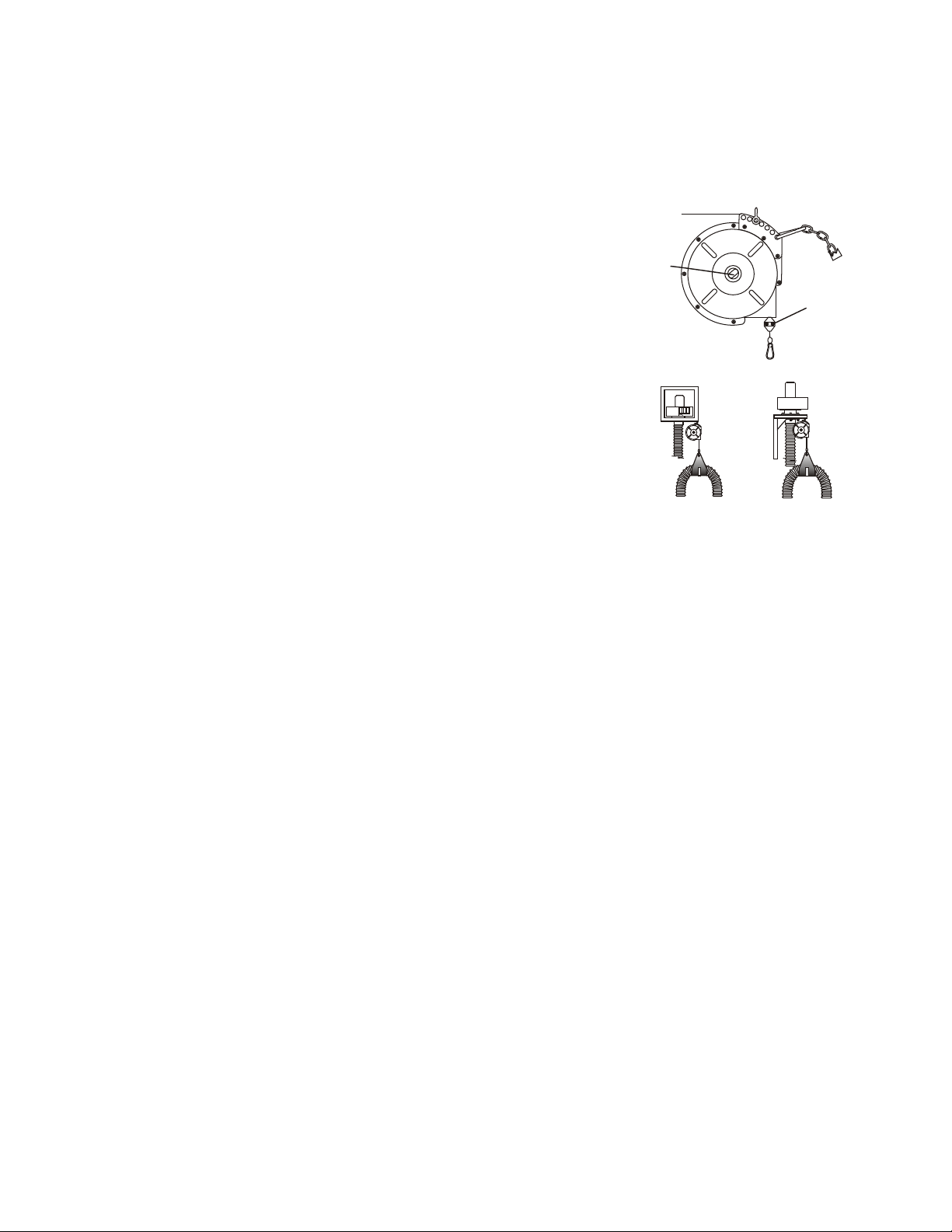
SAFETY
CHAIN
RUBBER
STOP
MECHANISM
TENSIONING
HEX NUT
STEEL CABLE
WITH
SAFETY CLIP
THE BA BALANCER INSTALLED ON THE
CEILING AND WALL PLATFORM. FOR DUAL
SYSTEMS, TWO BALANCERS MAY BE USED,
ONE ON EACH SIDE OF THE PLATFORM.
CLEVIS WITH LOCKING
COTTER PIN
Page 3
NOTE: IF AN LFT RETRACTOR WAS SUPPLIED, SEE ADDITIONAL INSTRUCTIONS SUPPLIED

CAR-MON PRODUCTS, INC. 1225 Davis Road, Elgin, IL 60123 Phone (847) 695-9000
BA BALANCER-CONTINUED
MAINTENANCE
No regular maintenance is required, but in the interest of safety, the cable and hanger bracket should be
checked periodically for wear. If wear is detected, replacement parts should be ordered and replaced
immediately.
LUBRICATION
Balancer is factory lubricated-no additional lubrication is required.
SPRING, CABLE, AND RATCHET ASSEMBLY
Unit should be sent to factory for authorized repair. Call 847-695-9000 and ask for customer service and
you will be given a return goods authorization number. Send unit freight prepaid for repair.
Please note that over tensioning the unit can cause the spring mechanism to break. This condition is not
covered under the manufacturer's warranty.
PULL-UP SETS
Instead of using a retracting balancer to pull tubing out of the way, a more economical method is using a
pull-up set with or without a winch. If this option is used, a separate instruction sheet will be included with
shipment.
LIMITED WARRANTY
Car-Mon Products, Inc. shall replace or repair at its discretion any products or components sold or
manufactured which prove to be defective in workmanship or materials within 1 year from date of shipment.
The foregoing is in lieu of all warranties, expressed or implied, and all other obligations or liabilities on
behalf of the company, regarding products it may manufacture or sell. Except as otherwise provided herein,
the purchaser accepts the product "as is".
No warranty is made regarding the suitability or compatibility of any Car-Mon product for a particular
application or purpose unless specifically stated. The Customer is responsible for the final selection and
utilization of Car-Mon products for their use. The Customer assumes all liability for the consequences of
performance, application, use and/or misuse by employees of products purchased from Car-Mon Products,
Inc.
In no event shall Car-Mon Products, Inc. be liable for consequential or special damages; for transportation,
labor, or other charges for adjustment, replacement, installation, incorrect electrical connections,
overloading of motor, performance at low voltage, or other alterations which may be performed in
connection with such products. The warranty specified herein is waived in the event that the Distributor,
Contractor, or Purchaser perform any unauthorized repairs or modifications to the product.
With regard to products or components which are furnished by Car-Mon, Inc. but not manufactured by Car-
Mon, Inc., the warranty obligation of Car-Mon shall be limited to and be the same as that of its supplier.
Page 4
Other CAR-MON Ventilation Hood manuals
Popular Ventilation Hood manuals by other brands

FALMEC
FALMEC Marte Pro T90W3P Instruction booklet

Taurus
Taurus T60IXAL manual

Teka
Teka TL-2000 instruction manual

DeDietrich
DeDietrich DHC 106 E1 installation instructions

Electrolux
Electrolux LFV619K user manual

Sirius Satellite Radio
Sirius Satellite Radio S-DDH3 Installation, Use and Maintenance Instruction

Empava
Empava EMPV-30RH05 Installation and operation manual

Smeg
Smeg KSE912NX2 instruction manual

Whirlpool
Whirlpool 761883306 installation instructions

Bellini
Bellini BR603GCX-1 Installation and user manual

FALMEC
FALMEC SILENCE FNLUM36W5SS Instruction booklet

Franke
Franke FDP 906 I Instructions for use and installation