2
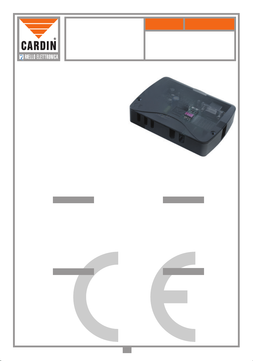
RADIO RENO S449
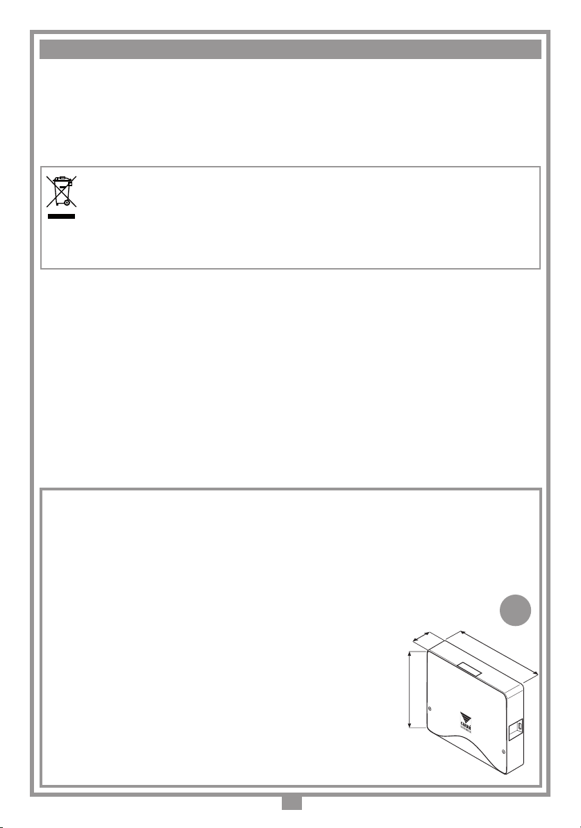
Dimensioni di ingombro
RXPR RENO
11-06-01
DM0538 Description :
Product Code :
Date :
Drawing number :
P.J.Heath
CARDIN ELETTRONICA S.p.A - 31020 San Vendemiano (TV) Italy - via Raffaello, 36 Tel: 0438/401818 Fax: 0438/401831
Draft :
All rights reserved. Unauthorised copying or use of the information contained in this document is punishable by law
85
20
120
Prima di dar inizio all’installazione leggere attentamente il presente fascicolo. L’utilizzo dei prodotti
e la loro destinazione ad usi diversi da quelli previsti e/o consigliati, non è stato sperimentato dal
costruttore, pertanto i lavori eseguiti sono sotto la completa responsabilità dell’installatore.
Il presente manuale si rivolge a persone abilitate all'installazione di "APPARECCHI UTILIZZATORI
DI ENERGIA ELETTRICA" e richiede una buona conoscenza della tecnica, esercitata in forma
professionale. Il costruttore declina ogni responsabilità per eventuali danni provocati dalla mancata
osservanza nell'installazione delle norme di sicurezza attualmente in vigore.
Attenzione! Il simbolo indica che il prodotto alla ne della propria vita utile deve essere raccolto separatamente
dagli altri riuti. L’utente dovrà pertanto conferire l’apparecchiatura agli idonei centri di raccolta differenziata dei riuti
elettronici ed elettrici, oppure riconsegnarla al rivenditore al momento dell’acquisto di una nuova apparecchiatura di
tipo equivalente, in ragione di uno a uno. L’adeguata raccolta differenziata per l’avvio al riciclaggio, al trattamento e
allo smaltimento ambientalmente compatibile contribuisce ad evitare possibili effetti negativi sull’ambiente e sulla salute e
favorisce il riciclo dei materiali. Lo smaltimento abusivo del prodotto da parte del detentore comporta l’applicazione delle
sanzioni amministrative previste dalla normativa vigente nello Stato Comunitario di appartenenza.
Dichiarazione di conformità CE
Il costruttore dichiara che il sistema di radiocomando Morpheus è conforme alle disposizioni della
direttivacomunitaria99/05/CE (R&TTE)esonostateapplicateleseguentinormee/ospecichetecniche:
- EN 60950-1 = 2004; EN 300220-2 = 2010; EN 301489-3 = 2001; EN 301489-1 = 2008.
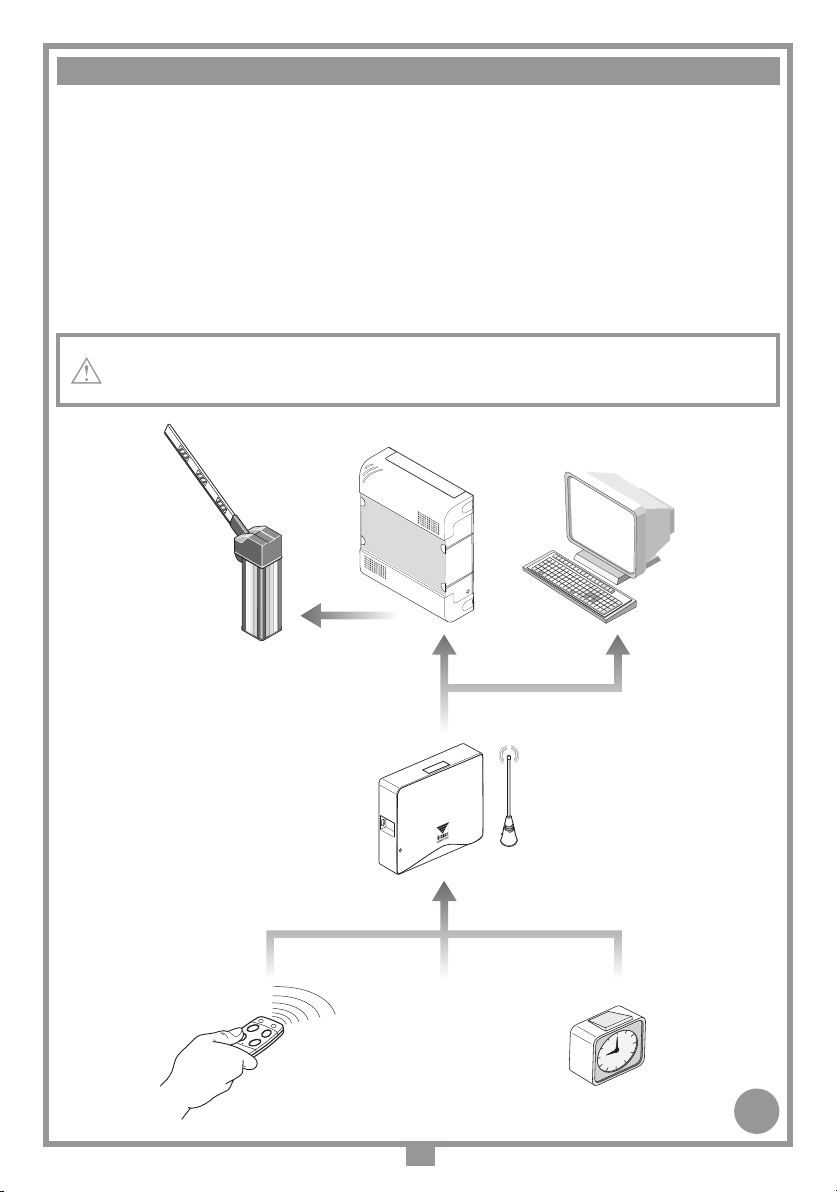
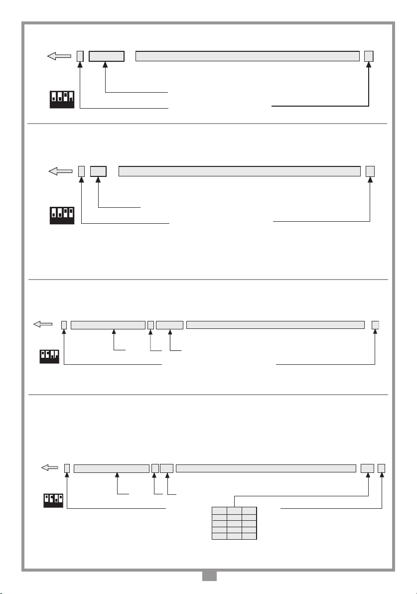
Descrizione
L'interfaccia MORPH433W00 è un dispositivo in grado di decodicare il segnale proveniente da
un transceiver Cardin mod. MORPHEUS e di presentare ai morsetti d'uscita un segnale digitale
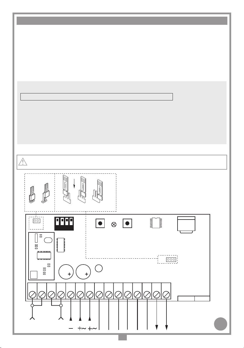
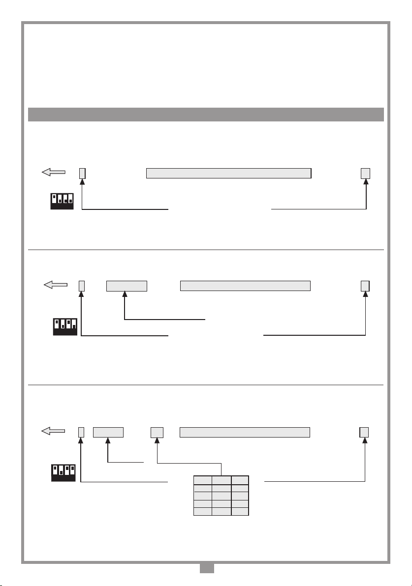
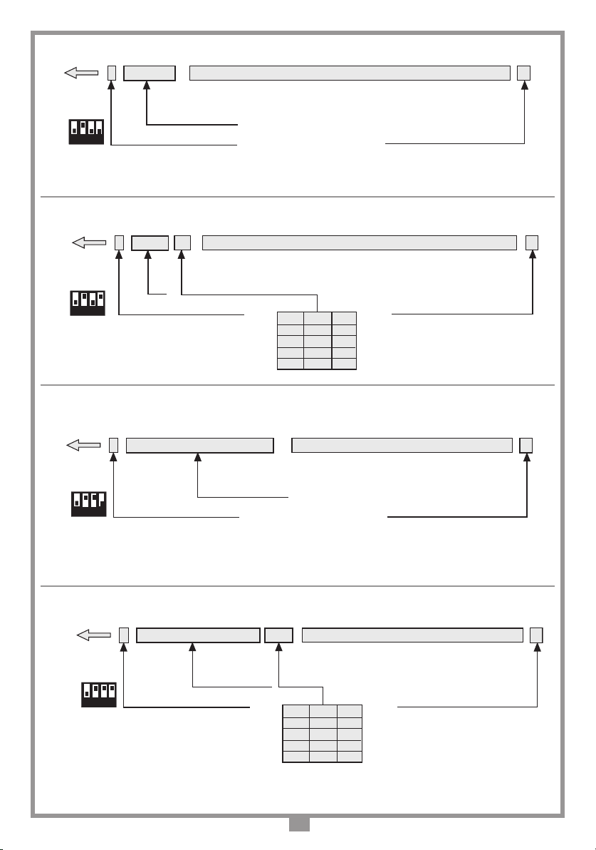
in cui si trova il codice del transceiver attivato, in 13 formati differenti, selezionabili tramite Dip-
switch a 4 vie. I segnali d'uscita seguono le normative ISO-3554, relative alla codica in formato
ABA Track (segnali RCP, RDP, CLS) oppure il protocollo WIEGAND (segnali DATA0 e DATA1
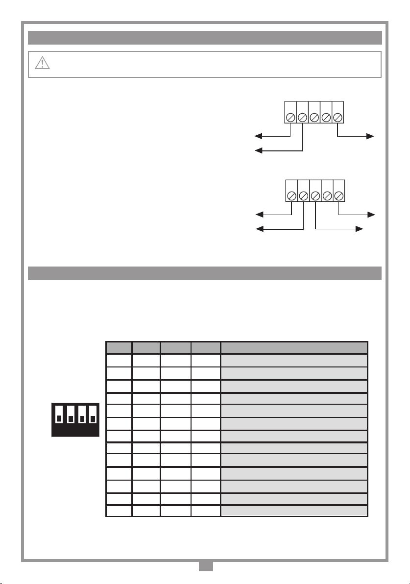
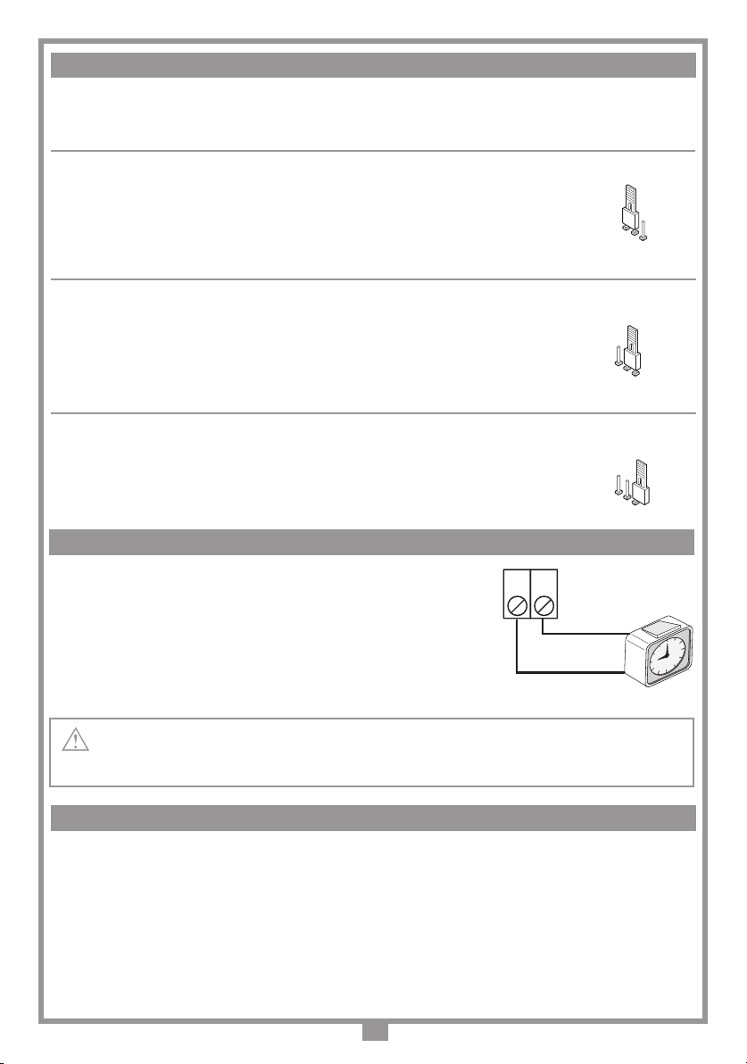
in 11 possibili congurazioni) o il protocollo SERIALE. È disponibile inoltre un contatto "EN" al
quale può essere collegato un temporizzatore oppure un interruttore con lo scopo di abilitare o
disabilitare l'interfaccia in diverse fascie orarie. L'uscita USB (indipendentamente dal protocollo
selezionato) permette l'interfacciamento con un personal computer.
CARATTERISTICHE TECNICHE
Alimentazione .......................................................................................................... 12/24 Vac/dc
Assorbimento...................................................................................................................... 45 mA
Portata: da 100 - 700 m in spazio libero con antenne esterna
Uscite: 5V - 12V - TTL Open Collector
Voh = 0.85 x Vdd: Vdd = 5V, Ioh = 1.2 mA max
Vdd = 12V, Ioh = 2.9 mA max
Vol = 0.4V, Iol = 15 mA max
Interfaccia multiprotocollo fissa
- frequenza di ricezione/trasmissione........................... 433,92 MHz
- tolleranza della frequenza ..................................................±10 kHz
- selettività.............................................................................±43 kHz
- modulazione............................................................................. FSK
- modulazione con ∆F ............................................................10 kHz
- impedenza di ingresso antenna...............................................50 Ω
- temperatura di esercizio............................................ -20°…+75 °C
ITALIANO AVVERTENZE ITALIANO
1
Dimensioni d'ingombro