Carefree of Colorado Universal Eclipse User manual

052547-021 Printed in USA May, 2006
OEM INSTALLATION MANUAL
ECLIPSE ARMS AND CANOPY
RV
THIS PUBLICATION COVERS MODELS FOR ORIGINAL EQUIPMENT MANUFACTURERS:
•Universal Eclipse
•Eclipse XL
These instructions apply to all models listed. Details and procedures unique to a specific
model are labeled appropriately.
TABLE OF CONTENTS
Product Overview.......................................................................................................................... 1
Eclipse Patio Awning Specifications:..............................................................................................1
Eclipse Patio Awning Options: .......................................................................................................1
Component Checklist..............................................................................................................................2
Installation .....................................................................................................................................4
Required Pre-Installation Preparation.....................................................................................................4
Installing an Awning Rail.........................................................................................................................4
Assembling the Awning ..........................................................................................................................5
Mounting the Awning..............................................................................................................................6
Installation – Electrical..................................................................................................................8
Single Switch Installation and Wiring......................................................................................................8
Wiring Diagram – Single Switch.....................................................................................................9
Multi-Switch Installation and Wiring......................................................................................................10
Wiring Diagram – Multiple Switch.................................................................................................12
Final Assembly............................................................................................................................13
Attaching the Fascia and Bottom Cover...............................................................................................13
Securing the Fabric...............................................................................................................................13
Removing the Temporary Assembly Pins.............................................................................................14
Installing the Alumaguard Tractioners..................................................................................................14

PROPRIETARY STATEMENT
The Eclipse Patio Awning is a product of Carefree of Colorado, located in Broomfield, Colorado, USA. The
information contained in or disclosed in this document is considered proprietary to Carefree of Colorado.
Every effort has been made to ensure that the information presented in the document is accurate and
complete. However, Carefree of Colorado assumes no liability for errors or for any damages that result
from the use of this document.
The information contained in this manual pertains to the current configuration of the models listed on the
title page. Earlier model configurations may differ from the information given. Carefree of Colorado
reserves the right to cancel, change, alter or add any parts and assemblies, described in this manual,
without prior notice.
Carefree of Colorado agrees to allow the reproduction of this document for use with Carefree of Colorado
products only. Any other reproduction or translation of this document in whole or part is strictly prohibited
without prior written approval from Carefree of Colorado.
SAFETY INFORMATION
WARNING
AWARNING INDICATES A POTENTIALLY HAZARDOUS SITUATION WHICH,IF NOT AVOIDED,COULD RESULT IN
DEATH OR SERIOUS INJURY AND/OR MAJOR PROPERTY DAMAGE.
CAUTION
ACAUTION INDICATES A POTENTIALLY HAZARDOUS SITUATION THAT MAY CAUSE MINOR TO MODERATE
PERSONAL INJURY AND/OR PROPERTY DAMAGE.IT MAY ALSO BE USED TO ALERT AGAINST UNSAFE PRACTICES.
NOTE: A note indicates further information about a product, part, or step.
Tip: A tip provides helpful suggestions.
Safety Notes:
•Always disconnect battery or power source before working on or around the electrical system.
•Always wear appropriate safety equipment (i.e. goggles).
•Always use appropriate lifting devices and/or helpers when lifting or holding heavy objects.
•When using fasteners, use care to not over tighten. Soft materials such as fiberglass and aluminum
can be "stripped out" and lose the ability to grip and hold.
Reference Publications located @ www.carefreeofcolorado.com:'
052547-001 Eclipse Arms and Canopy After Market Installation Manual
052547-021 Eclipse Arms and Canopy OEM Installation Manual
052547-201 Eclipse Owner's Manual
052547-301 Eclipse Service Manual
052987-002 WindSmart Installation & Operation Manual
052526-001 Direct Response Installation & Operation Manual
Carefree of Colorado 2145 W. 6
th
Avenue Broomfield, CO 80020
aScott Fetzer company 303-469-3324 ♦www.carefreeofcolorado.com
Table of Contents

Carefree of Colorado Installation Manual ECLIPSE,OEM
052547-021 1
PRODUCT OVERVIEW
The Eclipse Patio Awning uses unique “scissor” style arms that do not require vertical ground support. The
arms provide easy to use pitch adjustment—simply push together the pins on the arms, snap into the hole
set desired, and the pitch is set! The pitch can be left in any position and the Eclipse will roll up completely!
When the awning is rolled back out, it rolls out to pitch setting previously set.
The awning rollbar and arms are made from light weight, no-rust aluminum. The awning fabric is offered in
either heavy weight vinyl or the Sunbrella® fabric, one of the most durable, strongest, weather-resistant
and fade resistant fabrics on the market.
Eclipse Patio Awning Specifications:
ECLIPSE UNIVERSAL ECLIPSE XL
Maximum Extension: 8 foot 9 foot
Maximum Length: 21 feet 21 feet
Drop @ Min. Pitch: approximately 12 inches approximately 13.5 inches
Drop @ Max Pitch: approximately 40 inches approximately 45 inches
Extend Actuation: Gas Shock Gas Shock
Retract Actuation: Motorized roll up Motorized roll up w/ supplemental spring tension
Position Control: Motorized roll out/in
Power Requirements: 12VDC (operating range 10VDC to 14VDC) 1
Circuit Rating: 20 amp
Power Source: Motor and controls are routed and hardwired into the vehicle’s 12V system
OR 14.4V NiCD Battery (rechargeable)
Battery Charger: Input: 10VDC to 18VDC Time to Charge 2:2 Hours
Emergency Retract: Electrical override system (external power source)
Eclipse Patio Awning Options:
•Alumaguard Awning Wrap 3•WindSmart Auto-Retract System
4
•Uniguard Awning Wrap 3•Remote Control
5
•SunBlocker •12V Direct Response Auto-Retract System 4
NOTES:
1. Installation with optional SunBlocker shade requires a minimum power source of 12VDC
(operating range 12VDC to 14VDC)
2. Charge time is approximate requirement for a fully discharged battery to be fully charged.
3. Selected at time of initial order.
4. Windsmart and Direct Response Installations are not available with the Universal AM Eclipse w/ Battery
5. Remote Control available with auto-retract installations only
Table of Contents

ECLIPSE,OEM Installation Manual Carefree of Colorado
2 052547-021
COMPONENT CHECKLIST
Carefree of Colorado
Hardware
Rollbar (ordered seperately) 213
15
14131211
E0012c
10
8
7
5b
5a 6a
Arm Assemblies (see notes 1, 2)
24
25 26 29 18 19
6b
9
7
8
7
9
7
Standard XL
4Electrical
(Single Switch) 18 1916 17
2322
20 21
(Single Switch Connector Kit)
Electrical
(Multi-Switch)
(Single Switch Connector Kit)
28 29 30
Table of Contents

Carefree of Colorado Installation Manual ECLIPSE,OEM
052547-021 3
;ITEM DESCRIPTION QTY NOTE
1 Rollbar Assembly 1
2 Screw, HWHC #6 x 3/8 2
3 Tractioner 2 3
4 Screw, Truss Head, SQ Drive #10 x 5/8 2 3
5ALH Arm Assy, Idler 1 2
5BRH Arm Assy, Motorized 1 2
6ALH Arm Assy, Idler, XL only 1 2
6b RH Arm Assy, Motorized, XL only 1 2
7 Fascia Assy 2
8 Bottom Cover w/o switch 1
9 Bottom Cover w/ switch 1
10 Screw, Lag 1/4 x 1 1/2 8
11 Screw, Truss Head, SQ Drive #10 x 5/8 4
12 Screw, SHC #8 x 3/4 4
13 Screw, HWHC #6 x 3/8 2
14 Jumper Cable 1 4
15 Owner's Manual 1 4
16 Switch, DPDT, Momentary 1
17 Switch Plate, Single 1
18 Spade Connector Female 2
19 Screw #6 x 1/2 4
20 Receptacle Single Switch Install 1 5
21 Receptacle Seal/Cap 1
22 Spade Connector, Female, Insulated 2
23 Screw #6 x 1/2 2
24 Relay Module 1
25 Switch, DPDT, Latching 1
26 Switch, DPDT, Momentary 1
27 Switch Plate, Double 1
28 Receptacle Multi-Switch Install 1 5
29 Terminal, Female 5
30 Screw #6 x 1/2 4
Notes: 1. Awning configuration is specified at time of order, including awning length, fabric, color etc. Check
awning assembly against original purchase order.
2. The arm assemblies are configuration specific for the Universal Eclipse and the Eclipse XL and are
not interchangeable.
3. Screws and Tractioners are furnished with rollbar assemblies equipped with optional Alumaguard.
4. Place Jumper Cable (item 14) and Owner's Manual (item 15) with RV owner information. Installation
manual, if included, is for installer reference.
5. Connector plug is part of the RH arm assembly harness
Table of Contents

ECLIPSE,OEM Installation Manual Carefree of Colorado
4 052547-021
INSTALLATION
REQUIRED PRE-INSTALLATION PREPARATION
1. Park the vehicle on a flat surface and level the unit.
2. Check where the awning arms will be installed. The arms fit snug to the side of the vehicle and must not
cover or interfere with exhaust vents, lights etc.
3. If there is an awning rail installed, check that the awning rail runs the full length of the awning. Please
refer to the note under "Installing an Awning Rail" before proceeding.
4. Refer to the important note on page 6 about the required positioning of the centerline of the roll bar.
INSTALLING AN AWNING RAIL
NOTE: For canopies WITHOUT Alumaguard or Uniguard: If the vehicle already has a full-length
awning rail installed, skip to step 6.
For Alumaguard and Uniguard installations: If the existing awning rail is incorporated
into the coach trim or a drip rail, it will be necessary to mount a standard awning rail flat
on the coach wall. The awning rail and arms must be positioned so that any existing
trim does not interfere with the Alumaguard or Uniguard's "Flex Connect" or the awning
arm when in the closed position.
Standard Awning Rail
Mounted to Coach Wall
Flex Connect Must Be
Flat When the Awning
is Closed
UNIGUARD
E0050
Standard Awning Rail
Mounted to Coach Wall
ALUMAGUARD Hinged w/
Rubber Seal
Coach WallCoach Wall
Figure 1. Fabric Wrap Positioning.
1. Determine the optimum positioning of the awning so that the arms will not interfere with the door frame or
light fixtures. The centerline of the rail should be above the door opening a minimum of 6" for vinyl and 7" for
Alumaguard/Uniguard.
2. Awning rail must be level.
3. After determining mounting position, mark the position with a chalk line.
4. Seal the back of the rail with silicone sealant or putty tape.
5. Align the awning rail onto the wall and secure with #10 x 3/4”
screws. Use all the attach holes in the rail.
CAUTION
MAKE SURE THE SCREWS ARE SECURELY MOUNTED TO THE
STRUCTURAL FRAME OF THE VEHICLE.
6. Use a screwdriver to spread open one end of the awning rail
on the installation side.
7. File any sharp edges or burrs from the end of the rail. This will
help protect the awning fabric from damage during installation.
8. Spray inside the awning rail track with silicone lubricant.
Spread open the
end of the awning rail
T0012
Figure 2. Adjusting the Awning Rail.
Table of Contents

Carefree of Colorado Installation Manual ECLIPSE,OEM
052547-021 5
ASSEMBLING THE AWNING
If the installation is using an exterior wall mount plug/receptacle, go to step 4.
CAUTION
THE END CAP WITH THE OUTSIDE SWITCH IS SHIPPED ATTACHED TO THE ARM.USE CARE TO NOT DAMAGE THE
SWITCH,ENDCAP OR WIRING DURING INSTALLATION.
1. Decide on the location of the switches and control box to determine the cable routing.
2. If the motor and switch cables are to be routed through the RV wall at the bottom of the arm, no
modification is required. Go to step 4.
3. If the motor and switch cables are to be routed through the RV wall at the top of the arm:
3.1 For units with exterior switch: insert the 3-strand cable (switch cable) into the groove in back of
the channel. Allow 5“ of cable to extend from the bottom of the channel. Tie the end cap with
switch to the bottom of the channel to avoid damage during installation.
3.2 Remove the plastic wrap at the top of the motorized arm. Partially open the arm being careful to
not let the arm extend more than 6”.
NOTE: The arm is under tension from the gas shock located in the arm.
3.3 (Refer to Figure 10 page 10) Pull the motor cable out of the hole in the top of the channel.
3.4 For units with exterior switch, insert the switch cable through the hole from the back of the channel.
3.5 Route the excess wire up and out the top of the channel and close the arm.
3.6 Secure the top of the arm in the closed position using a plastic wrap or equivalent.
CAUTION
DURING ASSEMBLY AND INSTALLATION,THE ARM ASSEMBLIES MUST REMAIN PERPENDICULAR TO THE ROLLER
ASSEMBLY.FAILURE TO HANDLE THE ARM ASSEMBLIES CAREFULLY CAN BEND THE DRIVE SHAFT.
4. (Refer to Figure 3) Align the roller assembly with the end cap on the motorized arm assembly. Rotate
the end cap until the slot in the cap aligns with the empty slot in the roller assembly, and then press
the roller assembly fully into the cap. The end cap must seat squarely over the end of the roller
assembly when complete.
NOTE: The roller assembly must be oriented with the fabric going over the roller toward the
mounting surface.
5. Secure the end cap to the roller assembly using two #10 square-drive screws.
6. For the standard awning, repeat steps 4 through 6 to attach the non-motorized arm assembly to the
roller assembly.
7. For the XL awning, insert the spring into the roller assy then rotate the end cap until the slot in the cap
aligns with the empty slot in the roller assembly. Finish pressing the roller assembly fully into the cap
and secure using two # 10 square drive screws.
CAUTION
NO PRE-TENSION IS REQUIRED ON THE SPRING.Do not WIND OR TWIST THE SPRING (XL ONLY).
Roller Assembly
Align Slots
End Cap
#10 x 5/8 Screw (qty: 4)
End Cap
E0020
Align Slots
XL ONLY
Figure 3. Assembling the Awning.
Table of Contents

ECLIPSE,OEM Installation Manual Carefree of Colorado
6 052547-021
MOUNTING THE AWNING CAUTION
IT IS RECOMMENDED THAT AT LEAST THREE PEOPLE INSTALL THE AWNING DUE TO ITS SIZE AND WEIGHT.
Prior to mounting the awning, it is necessary to mark the first mounting hole. Do not drill at this time.
NOTE: For the bottom 3 mounting holes: if mounting into structure, use the 1/4 x 1 1/2 screws; if
not attaching into structure, use the furnished moly rivets.
The upper mounting holes must attach into structure using the screws provided. If
structural backing is not available for the upper mounting holes, it will be necessary to use
the aftermarket arm configuration so that the upper brackets can mount into the structural
members at the roof line.
1. Check the location where the awning is to be mounted. Ensure that the awning will not interfere with
other equipment on the vehicle, such as a slide out room, light fixtures, exhaust vents etc.
2. On the awning rail, mark the location of the centerline of the motorized arm assembly. From that
mark, measure down vertically a distance of 55 1/4" (62 1/2” for XL model) ± 1/4" from the centerline
of the awning rail. These will be the initial mounting holes.
55 1/4" 1/4”
62 1/2" 1/4” XL
E0022a
90
o
Typ.
Centerline
of Arm
Centerline
of Arm
Awning Length
Fabric Width
5”
(approx)
5”
(approx)
Awning Rail
= Flat Mounting
Surface Area
4 1/4” x 70”
6”-7”
Clearance
from top of
door
6”
(approx)
Approximate
Drill Area for
Upper Cable
Routing
7 1/2”
68 1/4”
75 1/2” XL
First Mounting
Hole (ref)
Approximate
Drill Area for
Lower Cable
Routing
Figure 4. General Layout and Installation.
3. Unroll the canopy one wrap. CAUTION
FOR THE XL MODEL,DO NOT UNROLL THE CANOPY MORE THAN 1TO 11/2 WRAPS.NO PRE-TENSION IS
REQUIRED ON THE SPRING AT REST (CLOSED). EXCESSIVE UNWRAP WILL CAUSE THE SPRING TO BE PUT IN
TENSION AT CLOSE,CAUSING THE AWNING TO NOT CLOSE PROPERLY.
4. With one person holding each arm, the third person should thread the polyrod (the plastic rod on the
edge of the fabric) into the awning rail, starting at one end. Carefully move across the vehicle, gently
pulling the fabric into the rail, until the awning is in the pre-determined location.
NOTE: While the awning fabric is fairly robust, care must be taken not to snag it on the
awning rail.
5. (Refer to Figures 4 and 5) Align the first mounting hole in the motorized arm with the location marked
in step 2. The arm assembly must be perpendicular to the awning rail.
IMPORTANT NOTE: For Uniguard and Alumaguard installations, the centerline of the roll bar must
be 3/4" ± 1/4" above the centerline of the awning rail.
Table of Contents

Carefree of Colorado Installation Manual ECLIPSE,OEM
052547-021 7
6. Drill a 5/32” hole at the first mounting hole and attach the motorized arm using a 1/4 x 1 1/2” lag
screw.
7. Confirm that the arm is perpendicular to the awning rail, attach the arm at the second mounting point
(shown in Figure 5) using a 5/32” drill bit and a 1/4 x 1-1/2” lag screw.
8. Position the roller assembly so that it is perpendicular to the motorized arm assembly. Position the
non-motorized arm perpendicular to the roller assembly.
9. Drill a 5/32” hole at the first mounting hole and attach the non-motorized arm using a 1/4 x 1 1/2” lag screw.
10. Check the alignment; the arm assembly must be
perpendicular to the roller assembly. When the
alignment is correct, drill and attach the arm at the
second mounting hole (shown in Figure 4) using a
5/32” drill bit and a 1/4 x 1-1/2” lag screw.
11. Hold the awning closed and carefully remove the
plastic wraps at the top of the arms. The awning
will open a few inches.
12. Cap or cover the exposed ends of the motor wires.
This is to prevent accidental shorting or
grounding during assembly.
13. Open the awning about 18” or until the top mounting
holes on the arms are visible. To open
•Use the supplied jumper cables and attach to the
emergency terminals located on the top of the
motorized head.
•Connect the other ends of the jumper leads to a
12V source. If the awning does not begin to
move, reverse the leads.
14. Using a 5/32” drill bit, locate and drill the mounting
holes.
15. Using two each 1/4 x 1-1/2” lag screws, attach the
top of the arm assemblies to the vehicle.
Upper Mounting Holes
(Arm Extended Out)
Lower Mounting Holes
1st Mounting Hole
2nd Mounting Hole
E0003
Mounting Holes
1/4 x 1 1/2 Screws Only
1/4 x 1 1/2 Screws
or
3/16 Moly Rivets
Figure 5. Arm Mounting Hole Locations.
Table of Contents

ECLIPSE,OEM Installation Manual Carefree of Colorado
8 052547-021
INSTALLATION –ELECTRICAL
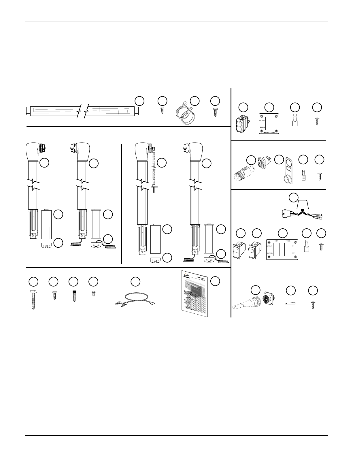
The Eclipse Patio Awning has two switch/wiring options. The single switch configuration has one interior
extend/retract switch. The multiple switch configuration has one power switch, one exterior extend/retract switch,
one interior extend/retract switch and a control box. The multiple switch wiring instructions start on page Error!
Bookmark not defined..
NOTES: •Failure to follow the wiring instructions in this publication may void the motor warranty.
•All wiring must conform to NEC (National Electrical Code) and local codes.
•DO NOT wire two or more motors to one switch—No parallel wiring.
CAUTION
ALWAYS DISCONNECT THE VEHICLE BATTERY AND ELECTRICAL SOURCES BEFORE WORKING WITH THE
ELECTRICAL WIRING AND COMPONENTS.
SINGLE SWITCH INSTALLATION AND WIRING
1. Determine the final location of the switch and mark the
location.
NOTE: The switch panel must be mounted within
32 inches of the point of entry for the cable.
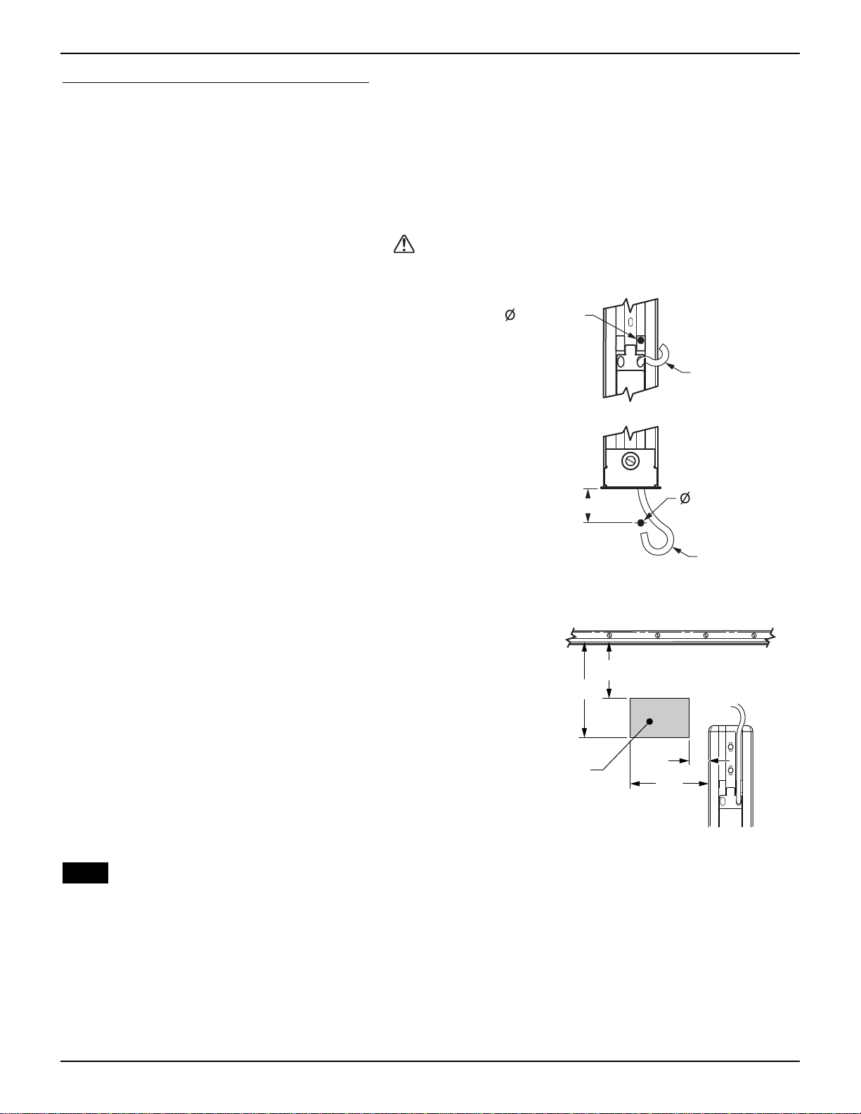
2. For installations using the cable with a direct
connection (no external plug)
2.1 (Refer to Figure 6) Drill a 5/16” hole through the
vehicle wall for the motor cable.
2.2 Route the cable through the holes to the location
of the switch panel.
2.3 Seal the cable and hole using a silicone sealant.
2.4 Go to step 4.
3. For installations using an external wall mount
plug/receptacle:
3.1 Drill a 15/16” hole through the exterior wall in the
location shown in Figure 7. Adjust the location
within the area to avoid structure, cabinetry etc.
3.2 Using a 2-wire cable, terminate the wire ends
with the female terminals provided.
3.3 Pull the terminated wires out through the hole.
3.4 Slide the rubber seal/connector cover onto the
back of the receptacle.
3.5 (Refer to Figure 9, Detail A) Attach terminated
wires to the back of the receptacle.
3.6 Secure the receptacle using two (2) #6 x 1/2
screws.
STOP – If an optional Windsmart or Direct Response system is being installed, complete the electrical installation
using the instructions included with the Auto-Retract kit. (052987-002 Windsmart, 052526-001 Direct Response)
4. At the switch panel location, use a 2 1/4” hole saw and cut a hole.
5. Route the cable through the hole and terminate the wires with spade connectors.
6. Push the switch into the faceplate until the locking tabs click into place behind the faceplate.
7. (Refer to Figure 9) Connect the wires from step 9 to the switch as shown.
5/16" Hole
Thru Existing
Slots
Top of Channel Routing
Bottom of Channel Routing
E0005
Motor Cable
1 1/2"
Motor Cable
5/16" Hole
Figure 6. Cable Pass Thru Drill Pattern.
E0033
1"
4"
3"
5"
Drill Area for
Wall Mount
Receptacle
Figure 7. Drill Location for Receptacle (EP).
Table of Contents

Carefree of Colorado Installation Manual ECLIPSE,OEM
052547-021 9
8. Run a 12 gauge wire (never use less than 14
gauge) from the power distribution panel
(auxiliary battery circuit) or equivalent. The
circuit should be protected by a 20 amp fuse.
NOTE: Minimum wire length and
maximum wire size should be selected to
assure adequate voltage.
9. Run a wire to chassis ground. Suitable
ground would be the vehicle chassis or
conductive structure connected to the
chassis.
10. (Refer to Figure 9) Route the two new
wires through the hole and terminate with
spade connectors. Connect to the control
switch.
11. Carefully push the wires and switch into the mounting hole, then attach the switch plate assembly
using four (4) #6 x 1/2” screws.
12. Restore vehicle power and test the awning operation.
Wiring Diagram – Single Switch
32”
Wall
Front View of
Switch Panel Rear View of
Switch Panel
E0008
Black Red
Carefree of Colorado
Ground +12VDC
LN
A
L
N
Black Black
Red Red
Detail A
Optional Wall Mount Connector
6
5B
4
3
2B
1
1Wire color from the motor may deviate on some models.
NOTE:
Standard Color
Red
Black
Deviation Color
Yellow
Brown
1
11
Figure 9. Single Switch Wiring Diagram.
WARNING
TERMINALS 1AND 4ARE CAPPED WITH FULLY INSULATED CONNECTORS.THESE TERMINALS MUST REMAIN
CAPPED AT ALL TIMES.
2 3/4"
(typ.)
2 3/4"
(min.)
Locking
Tabs
Covered
Terminals
on Bottom
E0010
2 1/4"
Figure 8. Single Switch Plate Assembly.
Table of Contents

ECLIPSE,OEM Installation Manual Carefree of Colorado
10 052547-021
MULTI-SWITCH INSTALLATION AND WIRING
1. Determine the final layout of the switches and the control box and mark the locations.
NOTE: When using only the wire harnesses furnished, the maximum distance from the cable
point of entry to the relay module is 48”. Maximum distance from the relay module to
the switches is 16”.
2. For installations using the cables with direct
connections (no external plug):
2.1 (Refer to Figure 10) Drill two 5/16” holes
through the vehicle wall for the motor cable
and exterior switch cable. Move the cables
out of the way to avoid damage while drilling.
2.2 Route the cables through the holes to the
location of the relay module.
2.3 Seal the cables and holes using a silicone
sealant.
2.4 Go to step 4.
3. For installations using an external wall mount
plug/receptacle:
3.1 Drill a 7/8” hole through the exterior wall in the
location shown in Figure 11. Adjust the
location within the area to avoid structure,
cabinetry etc.
3.2 Using a 3-wire cable and a 2-wire cable,
terminate the wire ends with the female
terminals provided.
3.3 Pull the terminated wires out through the hole.
3.4 (Refer to Figure 13, Detail A) Insert the
terminated wire ends into the back of the
receptacle.
3.5 Coat the backside of the receptacle flange with
silicone sealant and insert the receptacle into
the hole.
3.6 Secure the receptacle using 4 #6 x 1/2 screws.
STOP – If an optional Windsmart or Direct Response
system is being installed, complete the electrical
installation using the instructions included with the Auto-
Retract kit. (052987-002 Windsmart, 052526-001 Direct
Response)
4. (Refer to Figure 12) At the switch panel location, use a 2 1/4” hole saw and cut 2 holes 1 1/2” apart.
5. Separate the wires from the relay module into 3 groups:
•Brown, yellow and gray with spade terminals (interior switch),
•Black and red with spade terminals (interior power switch),
•Connector bundle with:
Brown, yellow and gray (exterior switch), and
Blue and white (motor).
NOTE: The relay module harness is supplied with one connector installed. The installer
must furnish the mating connector (p/n 1-480704) and terminals (p/n 350547-3) for the
exterior switch and motor cables. Vendor: AMP/Tyco Electronics.
5/16" Hole
Thru Existing Slots
Top of Channel Routing
Bottom of Channel Routing
E0004
External
Switch Cable Motor Cable
1 1/2"
Motor Cable
External
Switch Cable
5/16" Hole
Figure 10. Cable Pass Thru Drill Pattern (CS).
Figure 11. Drill Location for Receptacle (SP).
Table of Contents

Carefree of Colorado Installation Manual ECLIPSE,OEM
052547-021 11
6. Measure and cut away any excess cable from the motor and exterior switch cables. Terminate the
wires and install in the mating connector as shown in Figure 13 page 12.
NOTE: As an alternate installation, cutoff the existing connector from the control box bundle and
butt splice the cable wires and relay module wires as shown in Detail A on page 10.
7. Route the remaining wires, from the relay module, through the double hole.
Locking Tab
1 1/2"
E0011
4 1/4"
2 3/4" (min.)
2 3/4"
O 2 1/4"
Figure 12. Double Switch Plate Assembly.
8. Push the switches into the face plate until the locking tabs click into place behind the face plate.
NOTE: For the unit to operate correctly, the switches must be located and oriented as shown.
The power switch is a double throw, latching switch. The extend/retract switch is a
double throw, momentary contact switch.
9. Connect the wires from step 7 to the switches as shown in Figure 13 page 12.
10. Run a 12 gauge wire (never use less than 14 gauge) from the power distribution panel (auxiliary
battery circuit) or equivalent. The circuit should be protected by a 20 amp fuse.
NOTE: Minimum wire length and maximum wire size should be selected to assure adequate
voltage.
11. Run a wire to chassis ground. Suitable ground would be the vehicle chassis or conductive structure
connected to the chassis.
12. (Refer to Figure 13, page 12) Route the two new wires through the hole and terminate with spade
connectors. Connect to the power switch.
13. Carefully push the wires and switches into the mounting hole and attach the switch plate assembly
using 4 #6 x 1/2” screws.
14. Remove the paper backing from the adhesive foam on the relay module and press on a flat surface in
the proximity of the switches.
15. Restore vehicle power and test the awning operation.
Table of Contents

ECLIPSE,OEM Installation Manual Carefree of Colorado
12 052547-021
Wiring Diagram – Multiple Switch
48"
(Max. Distance with Furnished Wires)
16"
(Ref)
Red
Black Blue
White
Gray
Brown
Yellow
Gray
Brown
Yellow
Rear View of Connectors Shown
Wall of Vehicle
4
2
8
Gray
Yellow
Brown
1
5
2
6
Red
Black
Vehicle
Ground
+12VDC
Exterior Switch
Motor
Red
Black Blue
White
Gray
Brown
Yellow
Gray
Brown
Yellow
Detail
B
Alternate Wire Connection
Front View of
Switch Panel Rear View of
Switch Panel
E0032a
Carefree of Colorado
6
4
5
1
2
1
2
6
4
5
A
12
35
67
21
53
76
Rear View of Connectors Shown
Red
Black
Motor
Gray
Yellow
Brown
Exterior Switch
Red
Black
Gray
Yellow
Brown
Detail
A
Optional Wall Mount Connector
B
Relay
Module
16”
(Ref)
1Wire color from the motor may deviate on some models.
1
NOTE:
Standard Color
Red
Black
Deviation Color
Yellow
Brown
1
Figure 13. Eclipse Multi-Switch Wiring Diagram.
Table of Contents

Carefree of Colorado Installation Manual ECLIPSE,OEM
052547-021 13
FINAL ASSEMBLY
ATTACHING THE FASCIA AND BOTTOM COVER
1. Make sure the awning is completely closed.
2. Insert the tab, on the fascia, under the arm base
and rest it on the mounting plate.
3. Check that the gap between the top of the fascia
and the arm channel is approximately 1/8".
•If the gap is too large or too small, set the fascia
aside, loosen the mounting plate screws and
adjust the mounting plate height as required.
Tighten the screws and set the fascia in position.
4. Place the bottom cover beneath fascia. Carefully
tuck any wires into the bottom cover.
NOTE: There are tabs on the top of the
cover to correctly align the bottom
cover and fascia. The fascia should
seat in the groove of the cover.
5. Attach the cover to the fascia with the supplied
socket head screws using a 9/64” Allen wrench.
The bolts must go through the cover, the plate,
and the fascia.
6. Repeat for the other side.
7. Verify proper installation by opening and closing the awning.
SECURING THE FABRIC
1. Roll the awning in and out several times to make sure that the fabric is square on the rollbar.
2. Secure the canopy using one, #6 x 3/8" hex head screw at both sides of the awning.
Fabric Alumaguard
1"
#6 x 3/8
Screw
Polyrod
E0014
Fabric
1"
#6 x 3/8
Screw #6 x 3/8
Screw
Awning Rail
Awning RailAwning Rail Polyrod
Uniguard
Soft Connect
Figure 15. Securing the Fabric.
2.1 For vinyl awnings, place screw through awning rail, polyrod and canopy approximately 1” in from
the end of the fabric.
2.2 For Uniguard awnings, place screw through awning rail, polyrod and the soft connect material
approximately 1" in from the end of the fabric.
2.3 For Alumaguard awnings, place screw on the outer edge of the Alumaguard (not through the
Alumaguard).
Facia Tab
Facia
Seat Facia in
Groove
Alignment
Tabs
#8 x 3/4
Socket Head
Cap Screw
Bottom Cover
E0015
Mounting
Plate
Mounting
Plate
Screws
Figure 14. Attaching the Fascia and Bottom Cover.
Table of Contents

ECLIPSE,OEM Installation Manual Carefree of Colorado
14 052547-021
REMOVING THE TEMPORARY ASSEMBLY PINS
2 pins are inserted into the back of the left (idler) head for lateral stability
during installation. Using a pair of pliers, remove and discard both pins.
NOTE: The awning will operate with the pins in place; for long term
use, the pins must be removed to allow for climate variances.
INSTALLING THE ALUMAGUARD TRACTIONERS
This is only required when the optional Alumaguard metal wrap shield is installed.
(Refer to Figure 17)
1. Partially extend the awning until the Alumaguard is extended as shown.
2. Unlock the keeper and wrap the tractioner around the roller tube.
3. Position the tractioner under the Alumaguard with a 1/4” gap between Alumaguard and tractioner.
Lock the keeper.
4. Repeat for the other end of the rollbar.
5. Extend the awning to verify that the Alumaguard tractioners are lifting the Alumaguard up and over the
roller assembly.
6. To secure the tractioner, drill a 1/8” hole through the tractioner and rollbar, roughly center the hole
between two slots of the rollbar.
7. Secure with one (1) #10 square drive screw.
1/4" Gap
A
A
Center Screw
Between Slots on Roller
View
A-A
Position Tractioner
under Alumiguard
Keeper
E0013
Figure 17. Installing the Alumaguard Tractioner.
NOTES:
Figure 16. Removing the Assembly
Pins.
Table of Contents
This manual suits for next models
1
Table of contents
Other Carefree of Colorado Tent manuals
Popular Tent manuals by other brands

Kettler
Kettler Panalsol PNPA19021-0200 Assembly instructions

TINY LAND
TINY LAND Tent2001 Assembly instructions

Coleman
Coleman 2000008347 Setup instructions

Boutique Camping
Boutique Camping ADVENTURE STAR EMPEROR BELL TENT instruction manual

Vango
Vango Langley 400 instructions

Texsport
Texsport 02836 Assembly instructions

Harbor Freight Tools
Harbor Freight Tools 69039 Owner's manual & safety instructions

skandika outdoor
skandika outdoor FRONTIER Assembly instructions

Bugaboo
Bugaboo breezy sun instructions

FarmTek
FarmTek 104321 manual

Outwell
Outwell JACKSONVILLE 5SA quick start guide

toolport
toolport CONTOP 10m x 12m Assembly instructions