Carefree ALTITUDE User manual

070026-303 Printed in USA June, 2021
SERVICE MANUAL
ALTITUDE POWER PITCH ARMS
MOTORIZED VARIABLE PITCH PATIO AWNING
RV
Read this manual before servicing or using this product. Failure to follow the
instructions and safety precautions in this manual can result in personal injury and/or
cause the product to not operate properly.
For LED replacement parts and service procedures refer to 052584-301 “LED Service Manual for
Vertical Arms” available on-line at www.carefreeofcolorado.com
TABLE OF CONTENTS
Specifications................................................................................................................................ 1
Canopy Replacement....................................................................................................................2
Motor and/or Gear Replacement..................................................................................................4
For Awnings Fully or Partially Extended...............................................................................................4
For Awnings Fully Retracted................................................................................................................6
Replacing the Gas Shock .............................................................................................................8
Pitch Adjust Assembly and Parts Replacement.......................................................................10
Wiring Diagrams..........................................................................................................................12
Standard –Single Switch...................................................................................................................12
BT12 Wireless Awning Control System..............................................................................................12
Standard Maintenance................................................................................................................ 13
Fabric Care........................................................................................................................................ 13
Arm Care...........................................................................................................................................13
Emergency Override..........................................................................................................................14
Part Number Listing....................................................................................................................15
Part Number/Serial Number Location ................................................................................................15
Illustrated Parts List...........................................................................................................................15
BT12 Wireless Awning Control System Components and Kits...........................................................17

PROPRIETARY STATEMENT
The Altitude Power Pitch Patio Awning is a product of Carefree of Colorado, located in Broomfield, Colorado, USA.
Theinformationcontainedinordisclosedinthisdocumentis consideredproprietarytoCarefreeof Colorado. Every
efforthasbeenmadetoensurethattheinformationpresentedinthedocumentisaccurateandcomplete. However,
Carefree of Colorado assumes no liability for errors or for any damages that result from the use of this document.
The information contained in this manual pertains to the current configuration of the models listed on the title page.
Earliermodelconfigurationsmaydifferfromtheinformationgiven. CarefreeofColoradoreservestherighttocancel,
change, alter or add any parts and assemblies described in this manual, without prior notice.
Carefree of Colorado agrees to allow the reproduction of this document for use with Carefree of Colorado
products only. Any other reproduction or translation of this document in whole or part is strictly prohibited
without prior written approval from Carefree of Colorado.
SAFETY INFORMATION
This is the safety alert symbol. It is used to alert individuals to potential
personal injury hazards. Obey all safety messages that follow this symbol
to avoid possible personal injury or death.
WARNING
Indicates a hazardous situation, which if not avoided, could result in death
or serious bodily injury.
CAUTION
Indicates a hazardous situation, which if not avoided, may result in minor
or moderate bodily injury.
NOTICE
Indicates a situation that may result in equipment-related damage.
General Safety:
WARNING This product can expose you to chemicals including Di-isodecyl phthalate
(DIDP), Vinyl Chloride and Formaldehyde, which are known to the state of California to cause
cancer or birth defects or other reproductive harm. For more information visit
www.P65warnings.ca.gov
WARNING Shock Hazard. Always disconnect battery or power source before
working on or around the electrical system.
WARNING Always wear appropriate safety equipment (i.e. goggles).
CAUTION Always use appropriate lifting devices and/or helpers when lifting or
holding heavy objects.
NOTICE When using fasteners, do not over tighten. Soft materials such as fiberglass and
aluminum can be "stripped out" and lose the ability to grip and hold.
Carefree of Colorado www.carefreeofcolorado.com a Scott Fetzer company

Carefree of Colorado Service Manual ALTITUDE POWER PITCH
070026-303 1
SPECIFICATIONS
The Altitude Power Pitch provides motorized awning comfort
with Carefree's standards for looks, strength and dependability
with a successful blend of style, quality and economy.
The powered pitch adjustment offers continuous settings from
flat (3˚) to steep (16˚).
Theawningrollertubeandarmsaremadefromlight weight,no-
rust aluminum. The awning fabric is heavy weight vinyl.
White and RGB LED lighting is available with the strip mounted
in the roller tube or at the awning rail.
MAXIMUM EXTENSION:
88 inches
MAXIMUM LENGTH:
20 feet
PITCH:
FLAT
3˚
DROP:
approximately 6 inches
STEEP
16˚
approximately 26.5 inches
Angle is Canopy vs horizontal
Measurement is from centerline of Awning Rail to centerline of roller tube
MOTOR:
Power: 10VDC–14VDC
Circuit Rating: 15 amp
motor mounted in arm
POWER SOURCE:
Motor and controls are routed and hardwired into the vehicle’s 12V system
EXTEND ACTUATION:
Gas Shock
POSITION CONTROL:
Motorized roll out/in
AWNING
CONTROLLER:
NOTE:ORDERED SEPARATELY
Standard: 3 position, momentary ON, center OFF; DC polarity reversing switch with
dynamic brake
Optional: BT12 Wireless Awning Control System
COLOR:
Frame:
White, Black
Canopy:
Vinyl with Weatherguard or FLXguard. Refer to sales literature for options.
LED
LED strip mounted in roller tube or at the awning rail
Power:
1A, 12VDC
Control
White:
Single pole, single throw switch (SR0101) Note: The Switch kit is
ordered separately. Kit includes in-line fuse holder and 2A spade type fuse.
For an installer furnished control switch, see note under "Switch Installation".
RGB
IR (Infrared) Controller with sensor and remote.

ALTITUDE POWER PITCH Service Manual Carefree of Colorado
2 070026-303
CANOPY REPLACEMENT
1. Remove the canopy retaining screws in the awning rail.
2. Partially extend the awning.
3. Place stop blocks between the arm rollers and arm stops on both arms. Blocks should be 5"-6" in length.
4. Extend the awning. The arms will stop with the stop blocks in place. Check that the blocks are firmly
seated between the rollers and arm stops.
5. Continue to unroll the canopy from the roller tube. Continue until the fabric slot is aligned with the cutout
on the back of the idler head.
6. Disconnect power to the awning.
7. For awnings with LEDs in the roller tube:
7.1. On the motor side, remove the split grommet from the roller tube.
7.2. Carefully pull the wires and connectors out of the roller tube. Disconnect the connectors.
7.3. Tape or clamp the LED harness connector outside the roller tube to prevent it from falling back into the
roller tube. This can be done with a paper clip or similar device that will not damage the wires.
7.4. At the awning rail, clip the harness close to the canopy. Clamp the harness going into the vehicle to
prevent it from falling in the wall.
8. For awnings with LEDs at the awning rail: Disconnect the LED strip from the harness for white LEDS or
from the controller for RGB applications.
9. Remove the fabric retaining screws and washers in the roller tube.
10. Slide the fabric out of the awning rail and roller tube.
10.1. For canopies with LEDS at the awning rail: The LED rail adaptor is attached to the canopy and will slide
out with the canopy.
11. Clean and deburr the roller tube slots and awning rail as required. If not previously done, spread open
the awning rail track to facilitate inserting the new fabric.
Tip: Lightly spraying the slots with a dry silicone lubricant will help the fabric slide into the slot without
staining the material.
NOTE: While the awning fabric is fairly robust, care must be taken not to snag it on the awning rail.

Carefree of Colorado Service Manual ALTITUDE POWER PITCH
070026-303 3
12. Slide the new canopy into the roller tube and awning rail and center in the roller tube.
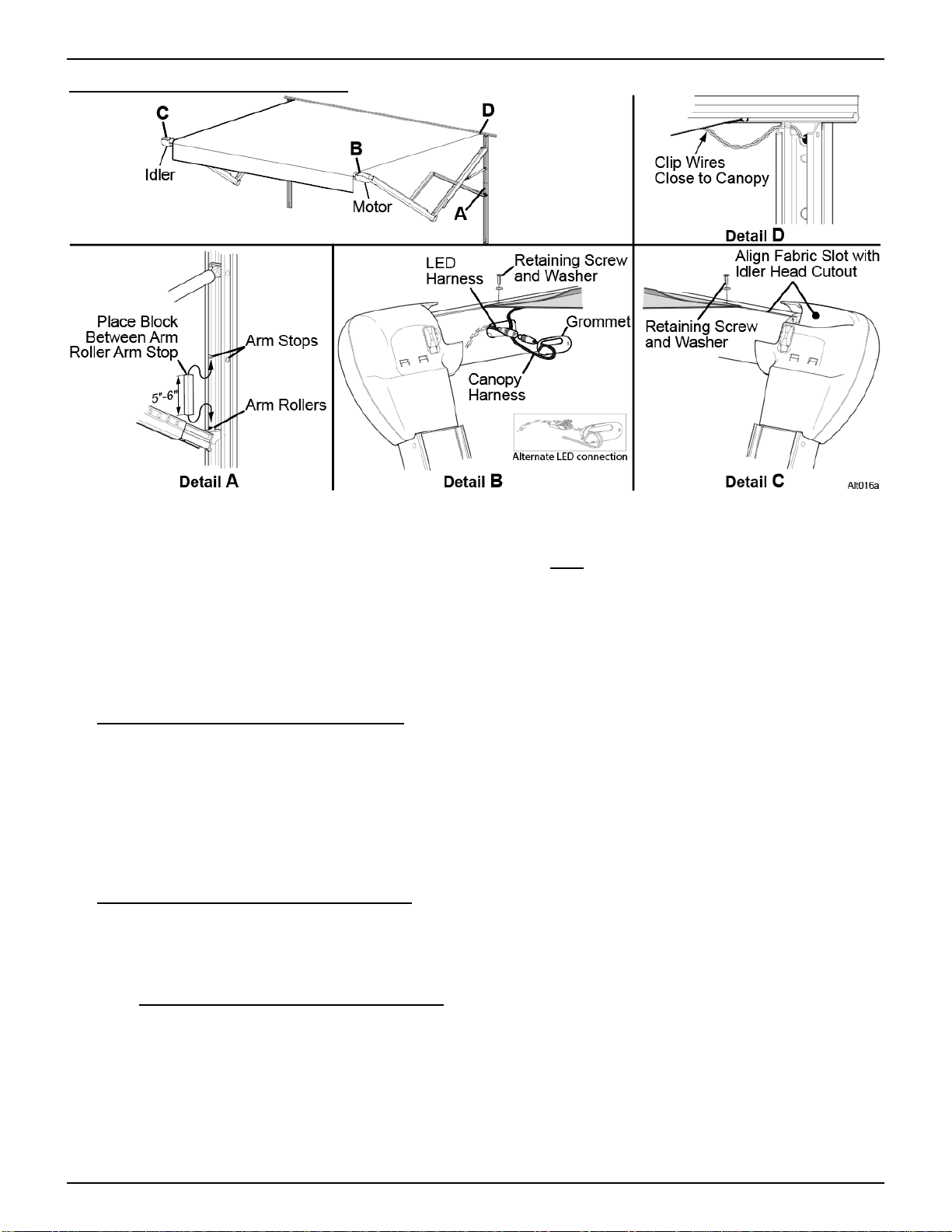
13. On one side of the canopy, secure the fabric tothe roller tube with a retaining screw and washer removed
previously. Screws and washers are placed under the valance and through the reinforcements on the
canopy.
14. On the opposite side of the canopy, pull the fabric taut and then, after stretching the fabric an additional
¼”, secure the fabric to the roller tube with the second retaining screw and washer.
15. Restore power.
16. Retract the awning and remove the blocks between the arm stop and arm rollers.
17. Check that the canopy is rolling up squarely onto the roller tube. Adjust as necessary.
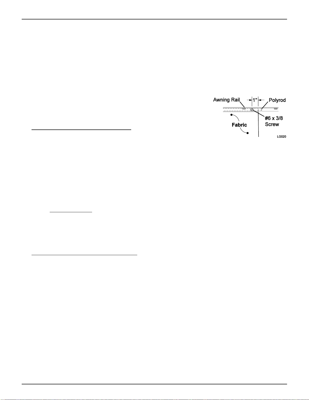
18. Place one (1) #6 x 3/8" screw through the awning rail, fabric and polyrod
approximately 1" in from the fabric edge. On the opposite side, pull the
fabric taut and then, after stretching the fabric an additional ¼”, place a
second retaining screw through the awning rail, fabric and polyrod.
19. For awnings with LEDs in the roller tube:
19.1. Connect the canopy harness connector and LED connector.
Then carefully push the connectors into the roller tube.
19.2. Placethesplit grommet over thecanopyharnessandpressthegrommet intothehole oftheroller tube.
19.3. At the vehicle wall, route the new canopy harness through the wall to the switch.
Tip: Tie the new harness to the old harness that was cut previously. Use the old harness to pull the
new harness throughthe wall to the desired location.
19.4. At the vehicle wall, provide a 3" loop of harness between the canopy and wall. Seal the wall entrance
hole and harness with a quality silicone sealant.
19.5. Connect the new harness to the switch. Two (2) .187, 18-24 awg female disconnects are provided
if connecting to a switch.
19.6. Alternate method: At the wall, splice the new harness to the existing harness using 24 awg butt
connectors. Push the connectors into the vehicle wall. Seal the wall entrance hole and wires with a
quality silicone sealant.
NOTE: Besuretoallowenoughharnessfromthecanopytoprovidea3"loopofharnessandadequate
lengthfortheconnectorstobe pushedinsidethewallbeforesealingtheholeandharness withaquality
silicone sealant.
20. For canopies with LEDs at the awning rail: Connect the LED strip to the harness for white LEDS or to
the controller for RGB applications.

ALTITUDE POWER PITCH Service Manual Carefree of Colorado
4 070026-303
MOTOR AND/OR GEAR REPLACEMENT
CAUTION The arms are under tension from the gas shocks. When the motor is removed
the roller tube will be able to free spin and both arms will extend from the gas shock tension. It will
be necessary to have at least one other person holding the roller tube and idler arm.
FOR AWNINGS FULLY OR PARTIALLY EXTENDED
1. Disconnect power to the awning.
2. Remove the front cover on the motor
side. To remove: Press in on both
sides of the rear cover in the area
shown. Rotate the cover up and off.
3. Disconnect the motor wires from the
motor cable.
4. Onthebackoftherearcoveropenthe
access cover and pull out the roller
tube retaining clip until it disengages
fromtherollertube. Theclipwill"latch"
in the detach position and can be left
in the cover.
5. Pull the roller tube from the motor
head.
6. Allow the motor arm to slowly extend
out to its maximum extension.
7. While firmly holding the idler arm and
roller tube, allow the awning to slowly
extend out to the maximum extension
of the canopy. Use a scaffold or
similardevicetosupportthemotorend
of roller tube.
NOTICE Do not allow the roller tube to drop toward the ground. The twisting motion can
cause serious damage to the idler arm and roller assembly.
8. Using a flat blade screw driver, press and release the two (2) rear cover tabs. Lift the rear cover off of
the motor frame.
9. Remove the three (3) motor mount screws, motor and gear box from the motor frame. Set parts aside.

Carefree of Colorado Service Manual ALTITUDE POWER PITCH
070026-303 5
10. Attach the new gear box and motor to the frame using the three (3) motor mount screws removed previously.
11. Snap the rear cover onto the motor frame.
12. Align the roller tube and insert the shaft into the head. It may be necessary to rotate the roller tube to
align the flats of the shaft with the opening.
13. Ensure that the roller tube is fully inserted into the head. With the roller tube shaft FULLY INSERTED, press
the retaining clip onto the shaft. The clip goes in only when the shaft is fully inserted. Press the clip until
it is firmly seated in the groove of the roller tube shaft.
14. Close the access cover.
15. Attach the motor wires to the arm cable. Ensure that the wire colors match.
16. Snap the front cover onto the rear cover. Hang the cover on the top and swing down until it clicks.
17. Restore power and test.

ALTITUDE POWER PITCH Service Manual Carefree of Colorado
6 070026-303
FOR AWNINGS FULLY RETRACTED
1. Disconnect power to the awning.
2. Remove the front cover on the motor side. To remove: Press in on both sides of the rear cover in the area
shown. Rotate the cover up and off.
3. Disconnect the motor wires from the motor cable in the arm.
4. Drill off the rolled rivet heads and press out the two rivets. Use care to not enlarge the holes in the parts.
5. Slowly extend the motor arm out from the wall.
6. Rotate the motor head and roller tube up to access the rear motor cover.
7. On the rear cover open the access cover and pull out the roller tube retaining clip until it disengages from the
roller tube. The clip will "latch" in the detach position and can be left in the rear cover.
8. Pull the motor head off of the roller tube.
9. Whilefirmlyholdingtheidlerarmandrollertube,allowtheawningtoslowlyextendouttothemaximumextension
of the canopy. Use a scaffold or similar device to support the roller tube.
NOTICE Do not allow the roller tube to drop toward the ground. The twisting motion can
cause serious damage to the idler arm and roller assembly.
10. Using a flat blade screw driver, press and release the two (2) rear cover tabs. Lift the rear cover off the
motor frame.
11. Remove the three (3) motor mount screws, motor and gear box from the motor frame. Set parts aside.
12. Position the motor frame in the arm channel. Ensure that the motor cable is extending out of the channel.
13. Attach the motor frame to the arm channel using four (4) 1/4" pop rivets (.25 minimum grip range).

Carefree of Colorado Service Manual ALTITUDE POWER PITCH
070026-303 7
14. Attach the gear box and motor to the frame using the three (3) motor mount screws removed previously.
15. Snap the rear cover onto the motor frame.
16. Align the roller tube and insert the shaft into the head. It may be necessary to rotate the roller tube to
align the flats of the shaft with the opening.
17. Ensure that the roller tube is fully inserted into the head. With the roller tube shaft FULLY INSERTED, press
the retaining clip onto the shaft. The clip goes in only when the shaft is fully inserted. Press the clip until
it is firmly seated in the groove of the roller tube shaft.
18. Close the access cover.
19. Attach the motor wires to the arm cable. Ensure that the wire colors match.
20. Snap the front cover onto the rear cover. Hang the cover on the top and swing down until it clicks.
21. Restore power and test.

ALTITUDE POWER PITCH Service Manual Carefree of Colorado
8 070026-303
REPLACING THE GAS SHOCK
CAUTION The gas shock has approximately 150 lbs. of pressure in the closed position. A
pressurized shock can open rapidly when removed or released and cause personal injury and property
damage.
1. Open the awning.
NOTE: The arm may not open completely when the shock has lost pressure or is removed. It may be
necessary to carefully pull the arm out and away from the vehicle to open the awning.
2. Drill out the arms stops from the rear
channel. Use caution to not oversize the
holes.
3. On the rear cover, open the access cover
and pull the retaining clip out to release the
roller tube.
4. Separate the roller tube and end cap. It will
be necessary to hold the roller tube and
arm. Allow the arm to extend out.
5. Support the roller tube and arm.
NOTICE Do not allow the roller tube to
drop toward the ground. The twisting motion
can cause serious damage to the other arm
and roller assembly.
6. Unscrew the shock barrel from the clevis in
the mounting channel.
Tip: Wearing a pair of rubber gloves will aid in
gripping the surfaces of the shock.
7. Unscrew the shaft from the clevis in the
arm joint. Set old shock aside.
NOTE: It may be necessary to use vice grips or pliers on the old shock to unscrew the shock from the clevis.
DO NOT use vice grips or pliers on the new shock. Damage to the surface of the shaft or damage to the
barrel can cause the new shock to not work correctly.
8. Unpack the new shock and carefully allow it to extend to its maximum length.
9. Coat the threads of the shaft of the new shock with a non-permanent thread lock (i.e. loctite) then screw
the rod into the clevis of the arm elbow. Hand-tighten only.
10. Lift and hold the arm up. The arm should be unfolded and extended as far as possible.
11. Coat the threads of the barrel of the new shock with a non-permanent thread lock (i.e. loctite) then screw
the barrel into the clevis in the mounting channel. Hand-tighten only. It will be necessary to grip and hold
the shaft while turning the barrel.

Carefree of Colorado Service Manual ALTITUDE POWER PITCH
070026-303 9
12. Attach the roller tube to the arm:
For Motor Side:
12.1. On the RH (motor) arm, press the roller tube shaft into hole in the
motor head. It may be necessary to twist the roller tube to align
the flats on the roller tube shaft with the flats in the motor head
bearing.
12.2. With the roller tube shaft FULLY INSERTED, press the retaining clip
onto the shaft. Theclip goes in only whenthe shaft is fully inserted.
Press the clip until it is firmly seated in the groove of the roller tube
shaft.
NOTICE The roller tube must be fully inserted into the head for the
clip to align with the groove on the shaft. The roller tube can disengage
if the clip does not seat in the groove of the shaft.
For Idler Side:
12.3. On the LH (idler) arm, press the roller tube shaft into hole in the
idler head.
12.4. With the roller tube shaft fully inserted, press the retaining clip onto
the shaft. Slide the roller tube shaft out of the head (about 3/16”)
until the clip aligns with the inner groove of the shaft. Press the clip
until it is firmly seated in the groove of the shaft.
13. Partially retract the awning. It may be necessary to lightly pull down on
the lower arm at the mounting channel until the rollers are past the
location of the arm stops. Always pull down from the bottom of the arm
to avoid pinching.
14. Install new arm stops where the old stops were removed. The stops are
3/16" pop rivets with a .063-.124" grip range.

ALTITUDE POWER PITCH Service Manual Carefree of Colorado
10 070026-303
POWER PITCH ADJUST ASSEMBLY AND PARTS REPLACEMENT
This procedure describes the steps to replace the power pitch adjust assembly and the arm rollers. The
procedures are the same for the RH and LH arms.
NOTICE This procedure requires two people. The second person is required to hold and support
the arm and roller tube during the procedure.
1. If replacing the complete power pitch adjust assembly, apply a pea sized dollop of grease to each side of
the new power pitch adjust assembly and then spread the remaining grease along the length of the drive
screw where shown.
NOTE: A small packet of
grease is shipped with the
new power pitch adjust
assembly.
2. Extend the awningto 75% of full extension in order
to access the power pitch adjust assembly.
3. Disconnect power to the awning and power pitch
system.
4. Remove the three mounting screws along with the
associated top cover. Set aside.
5. Disconnect the power pitch motor wires; one
white, one green.
6. If installed, remove the optional lower wire cover.
7. Drill out the rivet stops at the bottom of the arm channel,
both sides.
8. Using a flat blade screwdriver, remove the locking
wedge from the power pitch assembly housing.

Carefree of Colorado Service Manual ALTITUDE POWER PITCH
070026-303 11
9. Have one person support the arm and roller tube.
10. Simultaneously slide the power pitch adjust assembly out of the arm channel
and the bottom of the rear channel.
NOTE: The power pitch adjust assembly is not rigid and should be supported
during removal to maintain the alignment of the drive screw.
For roller replacement, remove the old rollers from the
posts.
11. Slide the new rollers onto the posts of the power pitch
adjust assembly.
NOTE: The rollers are shipped loose with the new power
pitch adjust assembly.
12. Slide the power pitch assembly a portion of the way into
the arm channel.
13. Slide the rollers and lower portion of the assembly into
the rear channel, orienting the pitch assembly as
shown.
14. Simultaneously slide the pitch adjust assembly into the
arm channel and rear channel until the pitch assembly
contacts the pivot pin near the center of the arm
channel.
NOTE: The power pitch adjust assembly is not rigid and
should be supported during installation to maintain the
alignment of the drive screw.
15. Install the locking wedge in the power pitch assembly housing and press
into place. It will snap in place when fully seated.
16. Install new 1/8" pop rivets in the holes where the rivet stops were drilled
out previously.
NOTE: New rivets are shipped loose with the new power pitch adjust
assembly.
17. Connect the power pitch motor wires to the wires from the arm, ensuring
that the wire colors match, and route the connectors into the housing.
18. Replace the power pitch assembly top cover and secure with three
mounting screws.
19. Restore power and test.

ALTITUDE POWER PITCH Service Manual Carefree of Colorado
12 070026-303
WIRING DIAGRAMS
STANDARD –SINGLE SWITCH
CONNECTOR
WIRE COLOR
LH CONNECTOR ORIENTATION
RH CONNECTOR ORIENTATION
RED→
+12VDC
+12VDC
WHITE→
RED
(motor wire)
BLACK
(motor wire)
BLUE→
BLACK
(motor wire)
RED
(motor wire)
BLACK→
Ground
Ground
BT12 WIRELESS AWNING CONTROL SYSTEM
The BT12 module provides an ignition lockout option. When the “IGN LOCK” is connected to the vehicle PCM or
other switched source the following parameters are set:
a) If Open = Awning Active
b) If tied to GND = RTL (Retract Then Lock) –Awning retracts, extend command disabled
c) If tied to +12Vdc = Standard –Extend command disabled
TheLEDconnectionisoptionaltoprovideLEDcontrolsthroughtheappandremoteforwhiteLEDSonly. WhiteLEDS
can also be installed per the standard LED installation without BT12 Controls.
The awning disable switch is a singlethrow, single poleswitch used with OEM Multiplexing Control Systems. Switch
is furnished by installer.

Carefree of Colorado Service Manual ALTITUDE POWER PITCH
070026-303 13
STANDARD MAINTENANCE
Maintaining the Carefree Manual Patio Awning is easy. Just follow these basic steps:
•Always operate the awning according to the instructions.
•Periodically check that the fasteners are tight. Tighten if necessary.
•Keep the awning fabric and arms clean.
FABRIC CARE
NOTICE Do not use oil based cleaners or any caustic, granulated, or abrasive type cleaners on
your Carefree product.
1. One of the best ways to keep the fabric looking good and to delay the needfor deep or vigorous cleanings
is to hosefabrics off on a monthly basis with clear water. This practice will help prevent dirt from becoming
deeply imbedded in the fabric. In most environments, a thorough cleaning will be needed every two to
three years.
2. When it’s time for a thorough cleaning, the fabric can be cleaned while still on an awning frame. Use a
soft brush and warm water with soap.
3. When cleaning the fabric, it is important to observe the following:
•Always use a natural soap, never detergent.
•Water should be cold to lukewarm, never more than 100F.
•Air-dry only. Never apply heat to the fabric.
•Always allow the fabric to dry thoroughly before rolling up the awning.
Mildew
Mildew is a fungus growth that looks like dirt. Vinyl coated polyester fabrics are mildew resistant because of
a chemical biocide in the vinyl coating. Under ordinary conditions, mildew will not appear. However, in areas
where high temperature and humidity are common, mildew can be a problem and required the material to be
washed more frequently. Thoroughly rinse the fabric with clean water and allow to air dry completely before
rolling up the awning.
Pooling
When water collects on the top of the fabric, this is known as "pooling". This can occur during inclement
weather or if a running air conditioner discharges over the awning. The water is dumped when the awning
is retracted. It is recommended that if water accumulates on the top; retract the awning in steps (8"-12") to dump
the water. This will help prevent thefabricfrom stretching or distorting.
The effects of wind and rain on an awning are unpredictable. Severe damage to the awning and the
vehicle may result. IF WIND OR EXTENDED PERIODS OF RAIN ARE EXPECTED,ROLL UP THE AWNING AND SECURE
FOR TRAVEL.
ARM CARE
The best method of keeping the arms and braces operating smoothly is to clean them. Dirt and debris can
cause the channels not to slide easily.
NOTE: Avoid introducing water into the motorized housings.
Periodically wash out the channels with running water (i.e. a hose) to keep them clean. If the arms still do
not move easily, lightly spray the contact and pivot points with a dry silicone lubricant after the arms have
been cleaned and dried thoroughly.
Hardware Maintenance
•Replace any parts that become damaged.
•Periodically check all mounting hardware, screws, lags, etc., and re-tighten when necessary.

ALTITUDE POWER PITCH Service Manual Carefree of Colorado
14 070026-303
EMERGENCY OVERRIDE
If power to the vehicle is not available, the awning can be safely retracted by jumping the motor using a 10V-14V
power source such as a cordless drill battery or car battery.
NOTICE Do not use a 110V power source for the emergency override procedure! Doing so will
permanently damage the awning! Do not use the emergency override without following the directions
below.
1. Remove the front cover. The cover snaps onto the rear cover.
To remove, press on both sides of the rear cover until the front
cover releases then lift the front cover off.
2. Detach the RED and BLACK wires from the cable to the
motor.
3. Attach jumper wires to the motor wires.
4. Connect the other ends of the jumper leads to a 10-14V
source. If the awning moves in the wrong direction, reverse
the leads. Maintain contact throughout the retraction
process.
5. When the awning is closed, remove the jumper wires and reattach the cable wires to the motor wires. Be
sure to match the wire colors.
6. Snap the front cover onto the rear cover. Hang the cover on the top and swing down until it clicks.

Carefree of Colorado Service Manual ALTITUDE POWER PITCH
070026-303 15
PART NUMBER LISTING
PART NUMBER/SERIAL NUMBER LOCATION
ILLUSTRATED PARTS LIST

ALTITUDE POWER PITCH Service Manual Carefree of Colorado
16 070026-303
Item
Part Number
Description
Notes
1
R002050BLK
Alt Pwr Ptch, Arm Assy, Motor Side, RH Black
R002050WHT
Alt Pwr Ptch, Arm Assy, Motor Side, RH White
2
R002051BLK
Alt Pwr Ptch, Arm Assy, Idler Side, LH Black
R002051WHT
Alt Pwr Ptch, Arm Assy, Idler Side, LH White
3
R001826
Kit, Gas Shock
4
R002024-001
Kit, Power Pitch Assy, Complete, Mil includes items 4,5 and rivets
R002024-002
Kit, Power Pitch Assy, Complete, Blk includes items 4,5 and rivets
5
R002064
Kit, Roller Replacement, SST Rivets
6
R001929-00X
Arm End Cap
7
R001930-00X
Kit, Hole Plug pkg of 4
8
R001931-00X
Cover Kit, Motor
2
9
R001832
Motor
10
R001833
Gear Box
11
R001932-00X
Cover Kit, Idler
2
12
R001835-00X
Kit, Clip Hole Cover Cap
13a
R001841-xxx
Roller Tube Assy, No LED 3" Dia
13b
R001842-xxx
Roller Tube Assy, w/ LED 3" Dia
14
R001836
Kit, Retaining Clip 1 ea LH & RH
15
R001837
Power Harness, Motor
16
R001933
Power Harness, Auxiliary
17
017719-006
Wire Cover, Lower pkg of 2
18
R041331-006
Wire Cover, Upper
19
R017715-005
Aftermarket Hardware Pack, Wht
4
R017715-006
Aftermarket Hardware Pack, Blk
4
20
R019487-003
Switch Kit, Awning
3
21
19XX00
Roller Tube, 4-Slot, No LED Aftermarket 3 1/2" Dia
19XX00RB
Roller Tube, 4-Slot, w/ White LED Aftermarket 3 1/2" Dia
Notes:
1. 00X = Color; 005= White; 006=Black. xxx= Length in inches. XX= Length in feet
2. Head cover kits include one front cover, one rear cover.
3. Switch kit includes switch, faceplate, screws and connector.
4. Aftermarket hardware pack (item 19) includes Switch Kit (item 20) and attaching hardware. Does not
include roller tube (item 21).
For LED replacement parts and service procedures refer to 052584-301 “LED Service Manual for
Vertical Arms” available on-line at www.carefreeofcolorado.com

Carefree of Colorado Service Manual ALTITUDE POWER PITCH
070026-303 17
BT12 WIRELESS AWNING CONTROL SYSTEM COMPONENTS AND KITS
The following kits and components are available for the BT12 Wireless Awning Control System
Kit Number
Included Components
AVAILABLE AFTERMARKET UPGRADE KITS
R001911
Included
SR0115
Included
901600
Included
Included
Included
901601
Included
Included
Included
901602
Included
Included
NOTES:
Kit components are paired at the factory. Separate components that are added or used for
replacements must be paired to the existing control module.

ALTITUDE POWER PITCH Service Manual Carefree of Colorado
18 070026-303
NOTES:
Other manuals for ALTITUDE
3
Table of contents
Other Carefree Lawn And Garden Equipment manuals