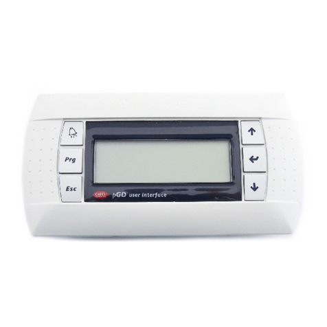
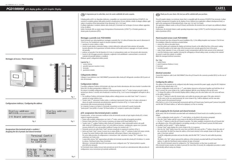
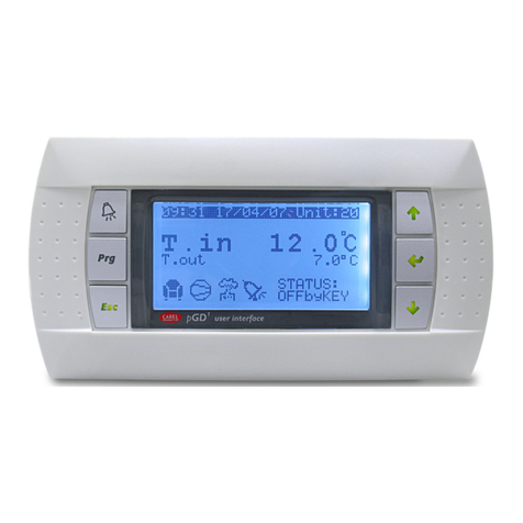
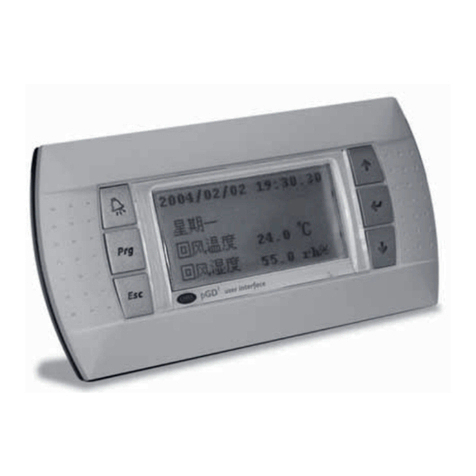
Carel pGD2 Manual

Technical leaflet
Foglio istruzioni
Betriebsanleitung
Mode d’emploi
pGD2/3
display graco per pCO
pCO graphic display
Folio de instrucciones

Indice / Contents / Sommaire / Index / Índice
Foglio istruzioni . . . . . . . . . . . . . . . . . . . . . . . . . . . . . . . . . . . . . . . . . 3
Technical leaflet . . . . . . . . . . . . . . . . . . . . . . . . . . . . . . . . . . . . . . . . 9
Vi ringraziamo per la scelta fatta, sicuri che sarete soddisfatti del vostro acquisto.
Thank you for your choice, we trust you will be satisfied with your purchase.
Nous souhaitons vous remercier de votre choix, certains que vous serez pleinement satisfait.
Wir danken Ihnen für Ihre Wahl und sind sicher, dass Sie mit Ihren Einkauf zufrieden sein werden.
Les agradecemos la selección realizada, estamos seguros que les satisfará su adquisición.
Mode d’emploi . . . . . . . . . . . . . . . . . . . . . . . . . . . . . . . . . . . . . . . . . 15
Anleitungen . . . . . . . . . . . . . . . . . . . . . . . . . . . . . . . . . . . . . . . . . . . 21
Folio de instrucciones . . . . . . . . . . . . . . . . . . . . . . . . . . . . . . . . . . . 27
Maschere /Screens / Masques / Masken / Pantallas . . . . . . . 33

3+050001041 rel. 2.2 - 13.10.2008
Descrizione
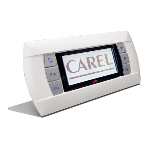
pGD2e pGD3sono dispositivi elettronici studiati per l’interfacciamento dell’utente con i controllori della famiglia pCO (contattare
CAREL per determinare il controllore che supporta PGD2/3 più adatto per la propria applicazione).
pGD2è un terminale grafico LCD monocromatico (blu/bianco) con risoluzione 320x240 pixel (cod. PGD2*******) e retroillumina-
zione a LED pGD3è un terminale grafico LCD a 256 colori con risoluzione 320x240 pixel (cod. PGD3*******) e retroilluminazione
a lampada fluorescente CCFL.
Montaggio a pannello (cod. PGD*00*F0*)
Questi terminali sono stati progettati per il montaggio a pannello con dima di foratura avente dimensioni pari a 194.5x128 mm +
6 fori circolari diametro 4mm, come indicato in Fig. 2 e 4.
Per l’installazione seguire le istruzioni riportate di seguito:
• Effettuare il collegamento dei cavi di alimentazione ed interfaccia seriale RS485;
• Inserire il terminale, privo di cornice frontale, nel foro del pannello, e mediante le 6 viti a testa svasata fornite nella confezione,
fissare il dispositivo al pannello come schematizzato in Fig. 2, verificare quindi il corretto posizionamento della guarnizione in
gomma del frontale;
• Infine, installare la cornice a scatto.
Attenzione: l’installazione deve essere effettuata in modo tale che l’operatore possa accedere al coperchio posteriore dello
strumento solamente tramite l’uso di un utensile.
L’apparecchio deve essere scollegato dalla tensione d’alimentazione prima dell’accesso da parte dell’operatore.
Montaggio a parete (cod. PGD*00*W0*)
Il montaggio a parete del terminale prevede l’iniziale fissaggio del retro contenitore (Fig. 3) ad una scatola da incasso standard
12/14 moduli (rif. normativa CEI23-48 – IEC60670).
Seguire quindi le indicazioni riportate di seguito:
• Fissare il retrocontenitore alla scatola da incasso utilizzando le 4 viti a testa svasata presenti all’interno del kit di assemblaggio
FISCHER®;
• Effettuare il collegamento dei cavi di alimentazione ed interfaccia seriale RS485;
• Pre-agganciare il frontale al retro contenitore: fissare il tutto come illustrato in Fig. 3, utilizzando le 4 viti a testa svasata presenti
nel sacchetto anch’esso all’interno dell’imballo;
• Infine, installare la cornice a scatto.
Attenzione: L’apparecchio deve essere scollegato dalla tensione d’alimentazione prima dell’accesso da parte dell’operatore.
Nota: per l’eventuale rimozione del frontale dal retro contenitore, togliere tensione allo strumento, quindi, dopo aver rimosso
manualmente la cornice a scatto ed aver svitato le quattro viti di fissaggio far leva con un cacciavite negli angoli superiori del
frontale per sbloccare i pre-agganci.
Avvertenze per l’installazione
Evitare il montaggio delle schede in ambienti che presentino le seguenti caratteristiche:
• umidità relativa maggiore di quanto indicato nelle specifiche tecniche;
• forti vibrazioni o urti;
• esposizione a getti d’acqua;
• esposizione ad atmosfere aggressive ed inquinanti (es.: gas solforici e ammoniacali, nebbie saline, fumi) con conseguente
corrosione e/o ossidazione;
• elevate interferenze magnetiche e/o radiofrequenze (evitare quindi l’installazione delle macchine vicino ad antenne trasmittenti);
• esposizione all’irraggiamento solare diretto e agli agenti atmosferici in genere;
• ampie e rapide fluttuazioni della temperatura ambiente;
• ambienti ove sono presenti esplosivi o miscele di gas infiammabili;
• esposizione alla polvere (formazione di patina corrosiva con possibile ossidazione e riduzione dell’isolamento).
• evitare di avvicinarsi con le dita ai componenti elettronici montati sulle schede per evitare scariche elettrostatiche (estremamente
dannose) dall’operatore verso i componenti stessi.
Avvertenze ulteriori
1. Una tensione di alimentazione elettrica diversa da quella prescritta può danneggiare seriamente il sistema;
2. Utilizzare capicorda adatti per i morsetti in uso. Allentare ogni vite ed inserirvi i capicorda, quindi serrare le viti. Ad operazione
ultimata tirare leggermente i cavi per verificarne il corretto serraggio;
3. Il touch-screen è un dispositivo sensibile per cui l’esercizio di pressioni eccessive o l’uso di oggetti appuntiti può danneggiarlo
irreparabilmente;
4. Per pulire il display usare un panno morbido asciutto e mai acqua;
4+050001041 rel. 2.2 - 13.10.2008
5. L’uso a temperature particolarmente basse può causare una visibile diminuzione della velocità di risposta del display. Questo è
da ritenersi normale e non è indice di malfunzionamento;
6. Per migliorare la resa visiva dell’applicazione, è consigliabile utilizzare colori pieni e immagini che non presentino dithering
(retinature). In caso contrario, specie a temperature elevate, può essere visibile del flickering (lampeggio dello schermo).
Installazione e montaggio
221
40.5
58 56.3
148
127.5
Montaggio ad incasso
Panel mounting
Montaggio a aparete
Wall mounting
Fig. 1
Fig. 2 Fig. 3
97,25
53
128
133,7
194,5
201,5
∅4 mm
dima di foratura
drilling template
Fig. 4

5+050001041 rel. 2.2 - 13.10.2008
Configurazione
pGD 2/3 viene configurato in fabbrica per le più comuni necessità d’uso, tuttavia, è possibile cambiare alcune impostazioni, per
adattarlo alle proprie esigenze.
I menù sono accessibili premendo un qualsiasi punto del touch screen contemporaneamente ai tasti (up) e Prg per almeno
1 secondo. In alternativa, è possibile accedere anche premendo contemporanemente i tasti (up) / (down) , (enter) per
almeno 1 secondo.
L’uscita invece avviene in uno dei modi seguenti:
1. premendo il tasto Esc;
2. automaticamente dopo 1 minuto dall’ultima volta che è stato premuto un tasto o toccato il touch screen;
3. alla pressione del simbolo “X”, quando visibile in alto a destra.
Come indicato in Fig. 5 alla sezione “Maschere” a fine documento, i tasti utilizzabili durante la configurazione sono visibili anche
sul lato destro del display:
Per attivare una voce è sufficiente premere il touch screen in corrispondenza della stessa o, in alternativa, premere i tasti (up) /
(down) fino a selezionarla, quindi, confermare con (enter).
Per modificare il valore di un campo, dopo averlo attivato (un campo è attivo quando è visibile il cursore lampeggiante) premere i
tasti (up) / (down) per cambiarlo e premere (enter) per memorizzarlo.
La pressione di Esc prima di (enter) annulla le modifiche apportate al campo.
Descrizione dei menù
Menù Principale
Il menù principale, “Display Configuration”, permette di selezionare le tre categorie principali di configurazione, che sono:
• Screen Settings: Impostazioni dello schermo;
• Network Configuration: Impostazioni della rete RS485;
• General Options: Impostazioni varie.
Menù “Screen Settings”
Vedere Fig. 6 alla sezione “Maschere” a fine documento
Le opzioni possibili sono:
• Contrast: Permette di impostare il contrasto del display (da 0 a 100, default: 50).
• Normal Brightness After: Permette di impostare dopo quanto tempo il display deve passare da “alta luminosità” a “luminosità
normale” dal’ultima pressione di un tasto o del touch screen. Impostabile da 30 s (30 s) a 15 minuti (15 min), default: 1 min.
• Screen Saver Timeout: Permette di impostare dopo quanto tempo il display deve spegnersi dopo essere passato a “luminosità
normale” dal’ultima pressione di un tasto o del touch screen. Impostabile da 30 s (30 s) a 4 ore (4 hrs), default: 15 min.
• Calibrate Touch Screen: È possibile calibrare il touch screen qualora si noti un disallineamento dello stesso. Per effettuare
l’allineamento, premere con precisione il centro dei crocini visualizzati in sequenza. La visualizzazione della scritta “Done: touch
the screen to ESC” indica la corretta riuscita dell’operazione. Se al contrario appare la scritta “Bad: touch to ESC and repeat” sarà
necessario ripetere l’operazione.
Menù “Network Configuration”
Vedere Fig. 7 alla sezione “Maschere” a fine documento
Le opzioni possibili sono:
• Teminal Address: Permette di impostare l’indirizzo del terminale (da 1 a 32, default: 32). Se si imposta il valore “--” (sono
visualizzati due trattini) il terminale comunicherà con la scheda pCO usando il protocollo “Punto-Punto” (non pLAN): i campi
“Baud Rate”, “Network Monitor” e “Setup I/O Board” scompariranno in quanto privi di significato;
• Baud Rate: Permette di impostare il baudrate di comunicazione pLAN. È possibile selezionare 62500 (default) oppure 115200
(da impostare solamente se tutti i dispositivi in rete sono configurati per questa velocità). Si noti che non tutti i dispositivi pLAN
supportano l’impostazione 115200;
• Network Monitor: Permette di visualizzare lo stato della rete (vedi paragrafo successivo);
• Setup I/O Board / Setup: Questi campi permettono di modificare la lista dei terminali associati ad ogni singola scheda pCO,
come descritto al paragrafo “pCO: assegnazione lista terminali...”.

6+050001041 rel. 2.2 - 13.10.2008
Network Monitor
Vedere Fig. 8 alla sezione “Maschere” a fine documento
Questa schermata permette di visualizzare lo stato della rete, indicando graficamente per ogni indirizzo quali dispositivi sono
collegati. Il significato dei simboli è il seguente:
Controllore pCO attivo in rete;
Terminale di qualsiasi tipo attivo in rete;
Terminale corrente;
Dispositivo non collegato.
Se viene rilevata attività di rete viene visualizzata la scritta “Online”.
Per uscire dalla schermata premere il tasto Esc.
pCO: Assegnazione lista terminali privati e condivisi
È possibile modificare la lista dei terminali associati ad ogni singola scheda pCO dal menù “Network Configuration” con la
seguente procedura:
1. selezionare l’indirizzo della scheda desiderata con i tasti (up) / (down) nel campo “Setup I/O Board” (solo le schede
effettivamente in linea sono selezionabili) e confermarlo premendo (enter). Se la rete pLAN non funziona correttamente,
oppure non è presente nessuna scheda pCO, non sarà possibile modificare il campo, che visualizzerà unicamente “--“ (due
trattini);
2. Premere il tasto “Setup”: verranno visualizzate in sequenza le maschere di Fig. 9 alla sezione “Maschere” a fine documento;
3. ora il tasto (enter) permette di spostare il cursore da un campo all’altro e (up) / (down) cambiano il valore del campo
corrente. Il campo P:xx visualizza l’indirizzo della scheda selezionata (nell’esempio in figura è la scheda 12);
4. per uscire dalla procedura di configurazione e memorizzare i dati selezionare il campo “OK ?”, impostare “Yes” e confermare
con il tasto (enter). In questa modalità, se il terminale rimane inattivo (nessun tasto premuto) per più di 30 s esce
automaticamente dalla procedura di configurazione senza memorizzare gli eventuali cambiamenti.
Attenzione: i terminali della linea pGD non possono essere configurati come “Sp” (shared printer) in quanto privi dell’uscita
stampante. La selezione di tale modalità non sortisce alcun effetto in ordine alla gestione dei messaggi di stampa via pLAN.
Menù “General Options”
Vedere Fig. 10 alla sezione “Maschere” a fine documento
Le opzioni possibili sono:
• Beep Volume: Permette di impostare il volume associato alla pressione dei tasti ed al touch screen. I valori possibili sono “off”
(spento), “low” (basso), “high” (alto). Default: high. Questo parametro non ha effetto sulla segnalazione di allarme, attivata o
disattivata dal pCO;
• Beep On: Serve ad impostare quando viene emesso il “beep”. I valori possibili sono: “active items” (che associa un suono alle
zone attive del display), “screen” (associa un suono a qualsiasi punto del touch screen) e “screen & keys” (associa un suono
sia al touch screen che alla tastiera). Default: “screen & keys”;
• Download Bar: attiva (“yes”) o disattiva (“no”) la visualizzazione della barra che indica lo stato di completamento della pagina.
Default: “yes”;
• Clear Cache Memory: cancella la memoria cache (utilizzata per accelerare la visualizzazione delle maschere). Questo tasto può
essere utile nel caso in cui l’aspetto grafico risulti corrotto. Alla pressione del tasto verrà visualizzata una finestra di conferma,
premere, quindi, “yes” per attivare l’operazione o “no” per annullarla;
• Display Firmware Update: inizia la procedura di aggiornamento firmware del PGD, come indicato al paragrafo successivo.

7+050001041 rel. 2.2 - 13.10.2008
Aggiornamento del firmware
È possibile aggiornare il firmware del terminale pGD2/3 quando vengono rese disponibili nuove versioni, mediante la funzione
“Display Firmware Update” raggiungibile dal menù “General Options”.
Gli aggiornamenti devono essere preventivamente caricati all’interno di un pCO collegato in rete pLAN, seguendo le indicazioni
fornite con la documentazione dei Tools di sviluppo applicativi del pCO.
Per eseguire l’aggiornamento del terminale selezionare “Display Firmware Update”.
Apparirà, quindi, una schermata simile a quella in Fig. 11 alla sezione “Maschere” a fine documento:
La versione attualmente installata è visibile nella seconda riga dall’alto.
La pressione del tasto Esc o della selezione “Abort” faranno ritornare al menù “General Options”.
Dopo alcuni secondi, se non sono disponibili versioni firmware diverse da quella attualmente installata, apparirà il messaggio “No
other versions available”.
Viceversa, apparirà una schermata simile a quella in Fig. 12 alla sezione “Maschere” a fine documento:
Ad ogni selezione corrisponde una versione firmware disponibile (nell’esempio indicato, la versione corrente è la “0.0” ed in rete
pLAN sono disponibili le versioni “1.2” ed “2.0”).
A questo punto, selezionare la versione che interessa. Potrà quindi apparire una finestra di attesa come quella in Fig. 13 alla
sezione “Maschere” a fine documento:
Al termine dello scaricamento verrà chiesto di confermare l’operazione di aggiornamento, vedere Fig. 14 alla sezione “Maschere” a
fine documento
La pressione di “No” cancellerà l’operazione mentre “Yes” attiverà la procedura.
Al termine della programmazione, della durata di circa un minuto, verrà visualizzato per alcuni secondi un messaggio “Successfull”
a conferma del corretto completamento della stessa.
Attenzione! L’interruzione dell’alimentazione durante la fase di programmazione potrebbe danneggiare il dispositivo e richiedere
assistenza tecnica.
Segnalazioni
Il terminale può rilevare alcune particolari condizioni di funzionamento, evidenziandole tramite messaggi a display:
• “Starting up, please wait…”: il terminale è appena stato acceso e/o sta attendendo di entrare in comunicazione;
• “Please wait...”: all’uscita dalla procedura di assegnazione dei terminali privati o condivisi di un pCO;
• “No network link: terminal alone”: quando nessun pCO viene rilevato se è selezionato il protocollo pLAN, dopo 40 s
dall’accensione, oppure dopo 20 s durante il normale funzionamento della rete;
• “I/O board (at address xx) fault”: nel caso di protocollo pLAN, dopo 8 s dalla perdita di comunicazione con il pCO che stava
visualizzando dati sul terminale in quel momento;
• “No I/O board configured for this terminal”: se il terminale non è previsto fra quelli configurati per i pCO in rete pLAN, dopo
40 s dall’accensione o dopo circa 8 secondi dall’uscita dalla procedura di assegnazione dei terminali di un pCO.

8+050001041 rel. 2.2 - 13.10.2008
Caratteristiche Tecniche
tensione di alimentazione: 24 Vac ±15%, 50/60 Hz oppure 30 Vdc ± 25%
potenza nominale: 10 W
Utilizzare un trasformatore di sicurezza in classe 2 di almeno 15 VA.
Connessioni di alimentazione al pGD2/3 (“PGD”)
Rispettare le seguenti prescrizioni:
• I terminali di alimentazione del PGD sono chiamati G e G0. La connessione avviene tramite morsetti removibili a 2 vie. Sezione
dei cavi ammessa: 0,5…1,5 mm2;
• Un fusibile obbligatorio dedicato da 800mAT deve essere posto esternamente tra l’alimentazione ed il terminale G.
• Se il trasformatore che alimenta il PGD è lo stesso che alimenta anche dispositivi pCO, allora il terminale G0 del PGD deve
essere collegato al terminale G0 del pCO.
• Attenzione: nel caso in cui sia richiesta la messa a terra dei secondari dei trasformatori di alimentazione, deve essere messo a
terra il terminale G0, sia per i pCO che per il PGD.
Interfacce
Seriale RS485 per la comunicazione con controllori pCO, tramite morsetti removibili a 3 vie. Utilizzare un doppino ritorto
schermato, AWG20-22, di lunghezza massima 200 m. La lunghezza totale della rete non deve superare i 500 m. La capacità tra i
cavi non deve superare i 90 pF/m.
Nota: per raggiungere la lunghezza massima utilizzare una topologia a bus con diramazioni che non superino i 5 m.
Caratteristiche funzionali
protocolli supportati: protocollo pLAN, protocollo “Punto-Punto” (solo modalità testo)
lampada di retroilluminazione: con due livelli di luminosità, “high” e “normal”
Caratteristiche generali
condizioni di funzionamento: pGD2: 0T50°C, 0 a 85% U.R. non condensante
pGD3: 0T45°C, 0 a 85% U.R. non condensante
condizioni di immagazzinamento: -10T70°C, 0 a 85% U.R. non condensante
grado di Protezione (IP)*: IP20
dimensioni (mm): vedi Fig. 1
inquinamento ambientale: 2
categoria di resistenza al calore e al fuoco: D
classe e struttura del software: A
durata della lampada di retroilluminazione: 30000 ore a 20 °C e luminosità “normal”
*: il frontale di pGD2 e pGD3 per montaggio a pannello (codice PGD****F**) è conforme al grado di protezione IP40.
Smaltimento del prodotto
Il prodotto è composto da parti elettroniche, in vetro, metallo ed in plastica. Il prodotto può inoltre essere fornito di
lampada CCFL che può contenere piccole quantità di mercurio. Tutte queste parti vanno smaltite secondo le normative
vigenti.
CAREL si riserva la possibilità di apportare modifiche o cambiamenti ai propri prodotti senza alcun preavviso.

9+050001041 rel. 2.2 - 13.10.2008
Description
pGD2and pGD3are electronic devices designed as the user interface for the pCO family controllers (contact CAREL to find out
the most suitable controller that supports the PGD2/3 for the specific application).
pGD2is a monochromatic (blue/white) LCD graphic terminal with 320x240 pixel resolution (code PGD2*******) and LED
backlighting.
pGD3is a 256-colour LCD graphic terminal with 320x240 pixel resolution (code PGD3*******) and CCFL backlighting.
Panel installation (code PGD*00*F0*)
These terminals have been designed for panel installation; the drilling template must measure 194.5x128 mm + 6 circular holes,
diameter 4 mm, as shown in Fig. 2 and 4.
For installation, proceed as follows:
• Connect the power and RS845 serial interface cables;
• Insert the terminal, without the front frame, into the opening in the panel, and using the 6 countersunk screws supplied in the
packaging, secure the device to the panel as shown in Fig. 2, then check the correct positioning of the front rubber gasket;
• Finally, install the click-on frame.
Important: installation must be performed so that the operator may access the rear cover of the instrument only using a tool.
Turn off the device before handling it.
Wall-mounting (code PGD*00*W0*)
The wall-mounting of the terminal first requires the rear of the case (Fig. 3) to be fastened to a standard 12/14 module switch
box (as per CEI23-48 – IEC60670).
Then proceed as follows:
• Fasten the rear of the case to the switch box, using the 4 countersunk screws present inside the FISCHER®assembly kit;
• Connect the power and RS845 serial interface cables;
• Pre-fasten the front panel to the rear of the case: secure the entire assembly as illustrated in Fig. 3, using the 4 countersunk
screws included in the plastic bag inside the packaging;
• Finally, install the click-on frame.
Important: Turn off the device before handling it.
Note: to remove the front panel from the rear of the case, first remove power and after having manually removed the click-on
frame and having undone the four fastening screws, use a screwdriver as a lever to release the top corners of the front panel.
Installation warnings
Avoid assembling the devices in environments with the following characteristics:
• relative humidity greater than the value specified in the technical specifications;
• strong vibrations or knocks;
• exposure to continuous water sprays;
• exposure to corrosive or pollutant gases (e.g. sulphur or ammonia fumes, saline mist, smoke) so as to avoid corrosion and
oxidisation;
• strong magnetic and/or radio interference (therefore avoid installing the unit near transmitting antennae);
• exposure to direct sunlight or the elements in general;
• large and rapid fluctuations in ambient temperature;
• environments where explosives or mixes of flammable gases are present;
• exposure to dust (formation of corrosive patina with possible oxidation and reduction of insulation).
• avoid touching or nearly touching the electronic components fitted on the boards, so as to avoid electrostatic discharges
(extremely dangerous) from the operator to the components.
Further warnings
1. Using a different power supply from the one specified may seriously damage the system;
2. Use cable ends suitable for the terminals. Loosen each screw and insert the cable ends, then tighten the screws. When
completed, lightly tug the cables to check that they are tight;
3. The touchscreen is a sensitive device. Exerting excessive pressure or using sharp objects may cause irreparable damage.
4. Use a dry soft cloth to clean the screen and never use water;
5. Operation at particularly low temperatures may cause a visible decrease in the response speed of the display. This is normal
and does not signify a malfunction;
6. To improve the visual performance of the application, use full colours and images that do not feature dithering (wirings).
Otherwise, especially at high temperatures, flickering (display flashing) may be visible.

10 +050001041 rel. 2.2 - 13.10.2008
Installation and mounting
221
40.5
58 56.3
148
127.5
Montaggio ad incasso
Panel mounting
Montaggio a aparete
Wall mounting
Fig. 1
Fig. 2 Fig. 3
97,25
53
128
133,7
194,5
201,5
∅4 mm
dima di foratura
drilling template
Fig. 4

11 +050001041 rel. 2.2 - 13.10.2008
Configuration
pGD 2/3 is configured by the manufacturer for the more common user requirements. Nonetheless, some settings can be
changed, so as to adapt the device to specific needs.
The menus can be accessed by pressing any point on the touchscreen together with the (up) and Prg buttons for at least one
second. Alternatively, press the (up) / (down), (enter) buttons together for at least one second.
The following operations exit the menu:
1. pressing the Esc button;
2. automatically 1 minute after a button was pressed or the touchscreen touched;
3. pressing the “X” symbol when displayed at the top right.
As shown in the Fig. 6 in the “Screens” section at the end of the document, the buttons that can be used during the configuration
phase are also visible on the right side of the display:
To access an item, simply press the touchscreen on the corresponding indication, or press the (up) / (down) buttons until
selecting it and then confirm by pressing (enter).
To modify the value of a field, after having activated it (a field is active when the cursor is flashing inside), press the (up) /
(down) buttons to change the value and press (enter) to save it.
Pressing Esc before (enter) cancel the modifications made to the field.
Description of the menu
Main menu
The main menu, visible in the previous image “Display Configuration”, is used to select the main three configuration categories,
that is:
• Screen Settings: Settings relating to the screen;
• Network Configuration: Settings relating to the RS485 network;
• General Options: Various settings.
“Screen Settings” menu
See Fig. 6 in the “Screens” section at the end of the document.
The following options are available:
• Contrast: Used to set the contrast of the display (from 0 to 100, default: 50);
• Normal Brightness After: Used to set the time after the touchscreen or the buttons are last pressed that the display switches
from “high brightness” to “normal brightness”. The possible values range from 30 s to 15 min, default: 1 min;
• Screen Saver Timeout: Used to set the time after the touchscreen or the buttons are last pressed that the display switches off,
after having switched to “normal brightness”. The possible values range from 30 s to 4 hours (4 hrs), default: 15 min;
• Calibrate Touch Screen: The touchscreen can be calibrated if it is evidently misaligned. To align the touchscreen, press the exact
centre of the crosses displayed in sequence. The message “Done: touch the screen to ESC” indicates that the operation has
been completed correctly. If, on the other hand, the message “Bad: touch to ESC and repeat” is displayed, the operation will
need to be repeated.
“Network Configuration” menu
See Fig. 7 in the “Screens” section at the end of the document.
The following options are possible:
• Terminal Address: Used to set the address of the terminal (from 1 to 32, default: 32). If the value “--” is set (two dashes are
displayed) the terminal will communicate with the pCO board using the “Point-Point” protocol (not pLAN) : the “Baud Rate”,
“Network Monitor” and “Setup I/O Board” fields will then disappear, as they have no meaning.
• Baud Rate: Used to set the pLAN communication baud rate. The possible values are 62500 (default) or 115200 (used only if all
the devices in the network are configured for this speed). Note that not all the pLAN devices support the 115200 setting.
• Network Monitor: This is used to display the status of the network (see next paragraph)
• Setup I/O Board / Setup: These fields are used to modify the list of terminals associated with each individual pCO board, as
described in paragraph “pCO: Assigning the list of private...”.

12 +050001041 rel. 2.2 - 13.10.2008
Network Monitor
See Fig. 8 in the “Screens” section at the end of the document.
This screen is used to display the status of the network, indicating graphically which devices are connected for each address. The
meaning of the symbols is the following:
pCO controller active in the network;
Any type of terminal active in the network;
Current terminal;
device not connected.
If activity is detected on the network, the message “Online” is displayed.
To exit the screen press the Esc button.
pCO: Assigning the list of private and shared terminals
The list of terminals associated with each individual pCO board can be modified from the “Network Configuration” menu, as
follows:
1. select the address of the required board using the (up) / (down) buttons in the “Setup I/O Board” field (only the boards
that are effectively on-line can be selected) and confirm by pressing (enter). If the pLAN network is not working correctly,
or no pCO board is present, the field is not modifiable, and “--“ (two dashes) will be displayed;
2. Press the “Setup” button: the screens will be displayed in sequence, see Fig. 9 in the “Screens” section at the end of the
document:
3. now the (enter) button is used to move the cursor from one field to the next, and (up) / (down) change the value of
the current field. The P:xx field shows the address of the selected board (in the example, board number 12 has been selected);
4. to exit the configuration procedure and save the data, select the “OK ?” field, set “Yes” and confirm by pressing (enter).
Alternatively, if the terminal remains inactive (no button is pressed) for more than 30 s, the configuration procedure
is automatically ended without saving the changes.
Important: the pGD terminals cannot be configured as “Sp” (shared printer) as the printer output is not featured. Selecting this
mode has no effect on the management of printed messages sent via pLAN.
“General Options” menu
See Fig. 10 in the “Screens” section at the end of the document.
The following options are possible:
• Beep Volume: Used to set the volume associated to the the buttons and the touchscreen pressing. The possible values are “off”,
“low”, “high”. Default: high. This parameter has no effect on the alarm signal, which is activated or deactivated by the pCO;
• Beep On: Used to set when the “Beep” sounds. The possible values are: “active items” (associates a sound with the active area
of the display), “screen” (associates a sound with any point on the touchscreen) and “screen & keys” (associates a sound with
both the touchscreen and the keypad). Default: “screen & keys”;
• Download Bar: activates (“yes”) or deactivates (“no”) the display of the status bar that indicates the progress of the page.
Default: “yes”;
• Clear Cache Memory: deletes the cache memory used to accelerate the display of the screens. This function may be useful if
there are errors in the graphics. Pressing the button displays a window that prompts for confirmation. Press “yes” to
confirm the operation or “no” to abort it;
• Display Firmware Update: starts the pGD firmware update procedure, as described in the next paragraph.

13 +050001041 rel. 2.2 - 13.10.2008
Update the firmware
The firmware of the pGD2/pGD3terminal can be updated when new versions become available, using the “Display Firmware
Update” function, accessible from the “General Options” menu.
The updates must have previously been loaded onto a pCO connected in the pLAN network, following the instructions provided
with the documents on the pCO application development tools.
To update the terminal firmware, select “Display Firmware Update”.
A screen will then appear, similar to the one shown in Fig. 11 in the “Screens” section at the end of the document.
The currently installed version is shown on the second row from the top.
Pressing Esc or “Abort” returns to the “General Options” menu.
After a few seconds, if no firmware versions other than the one currently installed are available, the message “No other versions
available” will be displayed.
Viceversa, A screen will then appear, similar to the one shown in Fig. 12 in the “Screens” section at the end of the document.
Each button corresponds to a firmware version available (in the example, the current version is “0.0” and the versions “1.2” and
“2.0” are available in the pLAN network).
Then select the desired version. A wait dialogue box may appear, similar to the one shown in Fig. 13 in the “Screens” section at
the end of the document.
At the end of the download, the user will need to confirm the update, see Fig. 14 in the “Screens” section at the end of the
document.
Pressing “No” will cancel the operation. Pressing “Yes” starts the programming procedure.
At the end of the programming procedure, which takes around one minute, the “Successful” message will be displayed for a few
seconds, indicating that the operation was completed correctly.
Warning! Power supply interruption during the programming phase may damage the device and require for technical
assistance.
Signals
The terminal may detect a number of special operating conditions, and display them using the following messages:
• “Starting up, please wait…”: the terminal has just been switched on and/or is waiting to establish communication;
• “Please wait...”: when exiting the procedure for assigning the private or shared terminals for a pCO;
• “No network link: terminal alone”: if no pCO is detected when the pLAN protocol is selected, 40 s after switching on, or after
20 s during the normal operation of the network;
• “I/O board (at address xx) fault”: when using the pLAN protocol, 8 s after communication is lost with the pCO that was
displaying data on the terminal at that moment;
• “No I/O board configured for this terminal”: if the terminal is not among those configured for the pCO in the pLAN network,
40 s after switching on or around 8 s after exiting the procedure for assigning the terminals to a pCO.

14 +050001041 rel. 2.2 - 13.10.2008
Technical specifications
power supply: 24 Vac ±15%, 50/60 Hz or 30 Vdc ± 25%
rated power: 10 W
Use a class 2 safety transformer with a rating of least 15VA.
Power supply connections to the pGD2/3 (“PGD”)
Observe the following rules:
• The power supply terminals on the PGD are called G and G0. The connection is made using 2-pin removable terminals.
Possible cross-section of the wires: 0.5 to 1.5 mm2;
• A dedicated 800 mAT fuse must be installed externally between the power supply and terminal G;
• If the transformer that supplies the pGD is the same that also supplies “pCO” devices, then terminal G0 on the pGD must be
connected to terminal G0 on the pCO;
• Important: if the secondary of the power supply transformers needs to be earthed, then terminal G0 must be earthed, both on
the pCO and the pGD.
Interfaces
RS485 serial for communication with pCO controllers, via 3-pin removable terminals. Use a shielded twisted pair cable,
AWG20-22, maximum length 200 m. The total length of the network must not exceed 500 m. The capacitance between the wires
must not exceed 90 pF/m.
Note: to reach the maximum length use a bus layout with branches that do not exceed 5 m.
Functional characteristics
protocols supported: pLAN protocol, “Point-Point” protocol (text mode only)
backlighting: with two levels of brightness, “high” and “normal”
General characteristics
operating conditions: pGD2: 0T50°C, 0 to 85% rH non-condensing
pGD3: 0T45°C, 0 to 85% rH non-condensing
storage conditions: -10T70°C, 0 to 85% rH non-condensing
index of protection (IP)*: IP20
dimensions (mm): see Fig. 1
environmental pollution: 2
category of resistance to heat and fire: D
class and structure of the software: A
duration of the backlighting lamp: 30,000 hours at 20 °C and “normal” brightness
*: The front panel of the PGD2 and PGD3 for panel mounting (code PGD****F**) is compliant with IP40 index of protection.
Disposal of the product:
The product is made up of electronic, glass, metal and plastic parts. The product may also feature a CCFL lamp, which
may contain small quantities of mercury. All these parts should be disposed of according to the legislation in force.
CAREL reserves the right to modify the features of its products without prior notice.

15 +050001041 rel. 2.2 - 13.10.2008
Description
pGD2et pGD3sont des dispositifs électroniques conçus pour l’interfaçage de l’utilisateur avec les contrôleurs de la famille pCO
(contacter CAREL pour identifier le contrôleur supportant PGD2/3 le plus indiqué pour l’adapter à l’application spécifique).
PGD2 est une unité terminale graphique LCD monochromatique (bleu/blanc) avec résolution de 320 x 240 pixels (cod.
PGD2*******) et rétro-éclairée à LED, PGD3 est une unité terminale graphique LCD à 256 couleurs avec une résolution de 320 x
240 pixels (cod. PGD3*******) et rétro-éclairée avec une lampe fluorescente CCFL.
Montage sur panneau (cod. PGD*00*F0*)
Ces unités terminales ont été conçues pour le montage sur panneau avec un gabarit de perçage dont les dimensions sont
194.5x128 mm + 6 trous circulaires d’un diamètre de 4 mm comme l’illustrent les Fig. 2 et 4.
Pour l’installation suivre les instructions suivantes:
• Effectuer la connexion des câbles d’alimentation et de l’interface sérielle RS485;
• Insérer l’unité terminale, sans bandeau frontal, dans le trou du panneau et à l’aide de 6 vis à tête fraisée fournies dans
l’emballage, fixer le dispositif au panneau selon les schémas des Fig. 2, s’assurer que la position du joint en caoutchouc du
bandeau frontal est correcte;
• et enfin, installer le cadre qui s’emboîte par pression
Attention: l’installation doit être effectuée de façon à ce que l’opérateur puisse accéder au couvercle arrière de l’instrument
exclusivement en utilisant un outil.
Couper le courant avant toute intervention de l’opérateur.
Montage mural (cod. PGD*00*W0*)
Il montage mural de l’unité terminale prévoit au départ la fixation du boîtier arrière (Fig.3), à une boîte encastrable standard 12/14
modules (réf. Norme CEI23-48 – IEC60670).
Suivre ensuite les indications suivantes:
• Fixer le boîtier arrière à la boîte encastrable en utilisant les 4 vis à tête fraisée fournies avec le kit d’assemblage FISCHER®;
• Effectuer la connexion des câbles d’alimentation et de l’interface sérielle RS485;
• Pré-fixer le bandeau frontal à l’arrière du boîtier: fixer le tout conformément à la Fig. 3, en utilisant les 4 vis à tête fraisée
contenues dans le sachet lui aussi à l’intérieur de l’emballage;
• et enfin, installer le cadre qui s’emboîte par pression.
Attention: Couper le courant avant toute intervention de l’opérateur.
Remarque: pour éventuellement extraire le bandeau frontal de l’arrière du boîtier, couper le courant à l’appareil, puis, après avoir
enlevé manuellement le cadre qui s’emboîte par pression et avoir dévissé les quatre vis de fixation, utiliser un tournevis comme un
levier dans les quatre coins supérieurs du bandeau frontal pour débloquer les pré-fixations.
Avertissements pour l’installation
Éviter de monter les cartes dans des milieux dont les caractéristiques sont les suivantes:
• humidité relative supérieure à celle indiquée dans les spécifications techniques;
• fortes vibrations ou chocs;
• exposition à des jets d’eau;
• exposition à des atmosphères agressives et polluantes (ex.: gaz sulfuriques et ammoniacaux, brouillards salins, fumées) dont les
conséquences sont corrosion et/ou oxydation;
• interférences magnétiques et/ou radio-fréquences élevées (éviter par conséquent l’installation des machines à côté d’antennes
émettrices);
• exposition au rayonnement solaire direct et aux agents atmosphériques en général;
• fluctuations amples et rapides de la température ambiante;
• milieux dans lesquels sont présents des explosifs ou des mélanges de gaz inflammables;
• exposition à la poussière (formation d’une patine corrosive avec une oxydation et une réduction de l’isolement éventuelles);
• éviter d’approcher les doigts aux composants électroniques montés sur la carte pour éviter toutes décharges électrostatiques
(extrêmement nuisibles) de l’opérateur vers les composants.
Avertissements supplémentaires
1. Une tension d’alimentation électrique différente de celle prévue peut endommager sérieusement le système;
2. Utiliser des cosses adaptées aux bornes utilisées. Desserrer les vis et y introduire les cosses, puis serrer les vis. Lorsque
l’opération est terminée, tirer légèrement les câbles pour en vérifier le bon serrage;
3. L’écran tactile est un dispositif sensible, par conséquent des pressions excessives ou l’utilisation d’objets pointus peut
l’endommager de façon irréversible;

16 +050001041 rel. 2.2 - 13.10.2008
4. Pour nettoyer l’afficheur utiliser un chiffon sec et jamais d’eau;
5. L’utilisation à des températures particulièrement basses peut provoquer une réduction visible de la vitesse de réponse de
l’afficheur. Cette réaction est normale, il ne s’agit pas d’un dysfonctionnement;
6. Pour améliorer le rendement visuel de l’application, il est conseillé d’utiliser des couleurs pleines et des images ne présentant
pas de dithering (tramages). Dans le cas contraire, spécialement avec des températures élevées, un phénomène de flickering
(clignotement de l’écran) peut se vérifier.
Installation et montage
221
40.5
58 56.3
148
127.5
Montaggio encastrable Montaggio mural
Fig. 1
Fig. 2 Fig. 3
97,25
53
128
133,7
194,5
201,5
∅4 mm
gabarit de perçage
Fig. 4

17 +050001041 rel. 2.2 - 13.10.2008
Configuration
pGD 2/3 est configuré en usine pour les usages les plus courants, toutefois, il est possible de changer quelques programmations,
pour l’adapter à ses propres exigences.
Les menus sont accessibles en appuyant sur n’importe quel point de l’écran tactile simultanément aux touches (haut) et Prg
pendant au moins 1 seconde. Il est également possible d’y accéder en appuyant simultanément sur les touches (haut)/ (bas),
(Entrée) pendant au moins 1 seconde.
Pour quitter les menus agir de la façon suivante:
1. appuyer sur la touche Esc;
2. automatiquement après 1 minute après la dernière fois qu’une touche a été enfoncée ou que l’écran tactile a été touché;
3. en appuyant sur le symbole “X”, lorsqu’il est visible en haut à droite.
Comme l’indique la Fig. 6 à la section “Masques” à la fin du document, les touches utilisables pendant la configuration sont
également visibles sur le côté droit de l’afficheur.
Pour activer une option, il suffit d’appuyer sur l’écran tactile à hauteur de celle-ci ou, d’puyer sur (haut)/ (bas) jusqu’à sa
sélection, puis la confirmer avec (entrée).
Pour activer la valeur d’un champ, après l’avoir activé (un champ est actif lorsque le curseur clignotant est visible), appuyer sur les
touches (haut) / (bas) pour le changer et appuyer sur (entrée) pour le mémoriser.
La pression de Esc avant (entrée) annule les modifications apportées au champ.
Description des menus
Menu Principal
Le menu principal, “Display Configuration”, permet de sélectionner les trois principales catégories de configuration, à savoir:
• Screen Settings: programmations de l’écran
• Network Configuration: programmations du réseau RS485
• General Options: autres programmations
Menu “Screen Settings”
Voir la Fig. 6 à la section “Masques” à la fin du document.
Le options possibles sont les suivantes:
• Contrast: Permet de programmer le contraste de l’afficheur (de 0 à 100, défaut: 50);
• Normal Brightness After: Permet de programmer le laps de temps nécessaire à l’afficheur pour passer de “ haute luminosité” à
“luminosité normale” après la dernière pression d’une touche ou de l’écran tactile. Programmable de 30 s (30 s) à 15 minutes
(15 min), défaut: 1 min;
• Screen Saver Timeout: Permet de programmer la laps nécessaire à l’afficheur pour s’éteindre après être passé à “luminosité
normale” après la dernière pression d’une touche ou de l’écran tactile. Programmable de 30 s (30 s) à 4 heures (4 hrs),
défaut: 15 min;
• Calibrate Touch Screen: il est possible de calibrer l’écran tactile si l’on remarque un désalignement de celui-ci. Pour effectuer
l’alignement, appuyer avec précision sur le centre des marques de repérage affichées en séquence. L’affichage de l’indication
“Done: touch the screen to ESC” indique la réussite de l’opération. Si par contre l’indication suivante s’affiche “Bad: touch to ESC
and repeat” il sera nécessaire de répéter l’opération.
Menu “Network Configuration”
Voir la Fig. 7 à la section “Masques” à la fin du document.
Le options possibles sont les suivantes:
• Teminal Address: Permet de programmer l’adresse de l’unité terminale (de 1 à 32, défaut: 32): si l’on programme la valeur “--”
(deux tirets son affichés), l’unité terminale communiquera avec la carte pCO en utilisant le protocole “Point-Point” (non pLAN):
les champs “Baud Rate”, “Network Monitor” et “Setup I/O Board” disparaîtront car sans signification;
• Baud Rate: Permet de programmer le baud rate de communication pLAN. Il est possible de sélectionner 62500 (défaut)
ou 115200 (à programmer uniquement si tous les dispositifs en réseau sont configurés pour cette vitesse). Remarquer que la
programmation 115200 n’est pas supportée par tous les dispositifs pLAN;
• Network Monitor: Permet de visualiser l’état du réseau (voir § suivant);
• Setup I/O Board / Setup: ces champs permettent de modifier la liste des unités terminales associées à chaque carte pCO,
comme décrit au paragraphe “pCO: attribution liste unités terminales…”

18 +050001041 rel. 2.2 - 13.10.2008
Network Monitor
Voir la Fig. 8 à la section “Masques” à la fin du document.
Cette page-écran permet de visualiser l’état du réseau, en indiquant graphiquement pour chaque adresse quels sont les dispositifs
connectés. La signification des symboles est la suivante:
Contrôleur pCO actif en réseau
Unité terminale de tout type actif en réseau
Unité terminale courante
Dispositif non connecté
Si une quelque activité de réseau est détectée l’indication “Online” s’affiche.
Pour quitter cette page-écran appuyer sur Esc.
pCO: attribution liste unités terminales et partagées
Il est possible de modifier la liste des unités terminales associées à chaque carte pCO à partir du menu “Network Configuration”
selon la procédure suivante :
1. sélectionner l’adresse de la carte souhaitée avec les touches (haut)/ (bas) dans le champ “Setup I/O Board” (seules les
cartes effectivement en ligne sont sélectionnables) et la confirmer en appuyant sur (entrée). Si le réseau pLAN ne fonctionne
pas correctement ou si aucune carte pCO n’est présente, il ne sera pas possible de modifier le champ qui affichera uniquement
“--”(deux tirets);
2. appuyer sur la touche “Setup”: les masques de la Fig. 9 à la section “Masques” à la fin du document s’afficheront en séquence ;
3. maintenant la touche (entrée) permet de déplacer le curseur d’un champ à l’autre et (haut) et / (bas) changent la valeur
du champ courant. Le champ P :xx affiche l’adresse de la carte sélectionnée (dans l’exemple de la figure, il s’agit de la carte 12);
4. pour quitter la procédure de configuration et mémoriser les données sélectionner le champ ”OK ?”, programmer “Yes” et
confirmer avec la touche (entrée). Dans cette modalité, si l’unité terminale reste inactive (aucune touche enfoncée)
pendant plus de 30 s, on quitte automatiquement la procédure de configuration sans mémoriser les changements éventuels.
Attention: les unités terminales de la ligne pGD ne peuvent pas être configurées comme “Sp” (shared printer) car dépourvus de
sortie imprimante. La sélection de cette modalité ne produit aucun effet par rapport à la gestion des messages d’impression via p
LAN.
Menu “General Options”
Voir la Fig. 10 à la section “Masques” à la fin du document.
Les options possibles sont les suivantes:
• Beep Volume: Permet de programmer le volume associé à la pression des touches et de l’écran tactile. Les valeurs possibles
sont “off” (éteint), “low” (bas), “high” (haut), défaut: high. Ce paramètre n’a aucun effet sur la signalisation d’alarme, activée
ou désactivée par le pCO;
• Beep On: Sert à programmer l’instant où se déclenche le “beep”. Les valeurs possibles sont “active time” (qui associe
un son aux zones actives de l’afficheur), “screen” (associe un son à n’importe quel point de l’écran tactile) et “screen & keys”
(associe un son tant à l’écran tactile qu’au clavier). Défaut: “screen & keys”;
• Download Bar: active(“yes”) ou désactive (“no”) la visualisation de la barre qui indique l’état d’achèvement de la page.
Défaut: “yes”;
• Clear Cache Memory: efface la mémoire cache (utilisée pour accélérer la visualisation des masques). Cette touche peut être utile
si l’aspect graphique est corrompu. À la pression de la touche, une fenêtre de confirmation s’affichera, puis, “yes” pour activer
l’opération ou “no” pour l’annuler;
• Display Firmware Update: la procédure de mise à jour firmware du PGD commence, comme indiqué au paragraphe suivant.

19 +050001041 rel. 2.2 - 13.10.2008
Mise à jour du firmware
Il est possible de mettre à jour le firmware de l’unité terminale pGD2/3 lorsque de nouvelles versions sont disponibles, par
l’intermédiaire de la fonction “Display Firmware Update”, pouvant être atteinte à partir du menu “General Options”.
Les mises à jour doivent être téléchargées au préalable à l’intérieur d’un pCO connecté au réseau pLAN, en suivant les indications
fournies avec la documentation des Tools de développement d’application du pCO.
Pour effectuer la mise à jour de l’unité terminale sélectionner “Display Firmware Update”.
Une page-écran, semblable à celle de la Fig. 11 de la section “Masques” à la fin du document, s’affichera.
La version actuellement installée est visible sur la deuxième ligne en partant du haut.
La pression de la touche Esc ou de la sélection “Abort” feront retourner au menu “General Options”.
Après quelques secondes, si des versions firmware différentes de celle actuellement installée ne sont pas disponibles, le message
“No other versions available” s’affichera.
Vice versa, une page-écran, semblable à celle de la Fig. 11 de la section “Masques” à la fin du document, s’affichera.
À chaque sélection correspond une version firware disponible (dans l’exemple indiqué, la version courante est la “0.0” et en
réseau pLAN les versions “1.2” et “2.0” sont disponibles).
À ce point, sélectionner la version souhaitée. Une fenêtre d’attente comme celle de la Fig. 13 de la section “Masques” à la fin du
document pourra donc s’afficher.
À la fin du téléchargement la confirmation de l’opération de mise à jour sera demandée, voir la Fig. 14 à la section “Masques” à la
fin du document:
La pression de “No” effacera l’opération alors que “Yes” activera la procédure.
À la fin de la programmation, de la durée d’une minute environ, un message “Successfull” sera affiché pendant quelques secon-
des pour confirmer que l’opération a été correctement achevée.
Attention! L’interruption de l’alimentation pendant la phase de programmation pourrait endommager le dispositif et exiger
l’assistance technique.
Signalisations
L’unité terminale peut détecter quelques conditions de fonctionnement particulières, en les mettant en évidence via des messages
sur l’afficheur:
• “Starting up, please wait…”: l’unité terminale vient d’être allumée et/ou est en train d’attendre d’entrer en communication;
• “Please wait...”: à la sortie de la procédure d’attribution des unités terminales privées ou partagées d’un pCO;
• “No network link: terminal alone”: lorsque aucun pCO n’est détecté si le protocole pLAN est sélectionné, après 40 s de
l’allumage, ou après 20 s pendant le fonctionnement normal du réseau;
• “I/O board (at address xx) fault”: dans le cas du protocole pLAN, après 8 s de la perte de communication avec le pCO qui était
en train d’afficher les données sur l’unité terminale à ce moment-là;
• “No I/O board configured for this terminal”: si l’unité terminale n’est pas prévue parmi celles configurées pour les pCO en
réseau pLAN, après 40 s de l’allumage et après 8 s environ de la sortie de la procédure d’attribution des unités terminales d’un
pCO.

20 +050001041 rel. 2.2 - 13.10.2008
Caractéristiques techniques
tension d’alimentation 24 Vaa ±15%, 50/60 Hz ou 30 Vdc ± 25%
puissance nominale 10 W
Utiliser un transformateur de sécurité en classe 2 d’au moins 15 VA.
Connexions d’alimentation au pGD2/3 (“PGD”)
Respecter les consignes suivantes:
• les unités terminales d’alimentation de PGD sont appelées G et G0. La connexion se fait par des bornes amovibles à 2 voies.
Section des câbles admises: 0,5…1,5 mm2;
• Un fusible obligatoire dédié de r800mAT doit être placé à l’extérieur entre l’alimentateur et l’unité terminale G.
• Si le transformateur qui alimente le PGD est le même que celui qui alimente également les dispositifs pCO, l’unité terminale G0
du PGD doit être connectée à l’unité terminale G0 du pCO.
• Attention: si la mise à la terre des secondaires des transformateurs d’alimentation est requise, l’unité terminale G0 doit être
mise à la terre, tant pour les pCO que pour le pGD.
Interfaces
Sérielle RS485 pour la communication avec les contrôleurs pCO, par des bornes amovibles à 3 voies. Utiliser un câble à paire
retordu blindé, AWG20-22 d’une longueur maximale de 200 m. La longueur totale du réseau ne doit pas dépasser les 500 m. La
capacité entre les câbles ne doit pas dépasser les pF/m.
Remarque: pour atteindre la longueur maximale utiliser une topologie à bus avec des branchements ne dépassant pas les 5 m.
Caractéristiques fonctionnelles
protocoles supportés protocole pLAN, protocole “Point-Point” (uniquement modalités texte)
lampe de rétro-éclairage avec deux niveaux de luminosité “high” et “normal”
Caractéristiques générales
conditions de fonctionnement: pGD2: 0T50°C, 0 à 85% H.R. non condensante
pGD3: 0T45°C, 0 à 85% H.R. non condensante
condition de stockage: -10T70°C, 0 à 85% H.R. non condensante
degré de Protection (IP)*: IP20
dimensions (mm): voir Fig. 1
pollution environnementale: 2
catégorie de résistance à la chaleur et au feu: D
classe et structure du logiciel: A
durée de la lampe de rétro-éclairage: 30000 heures à 20 °C et luminosité “normale”
*: La façade de PGD2 et PGD3 pour le montage sur panneau (code PGD****F**) est conforme au degré de protection IP40.
Élimination du produit
Le produit est constitué de parties électroniques, en verre, métal et plastique. Le produit peut en outre être équipé
d’une lampe CCFL pouvant contenir de petites quantités de mercure. Toutes ces parties doivent être éliminées selon
les normes en vigueur.
CAREL se réserve le droit d’apporter toutes modifications ou tous changements à ses produits sans aucun préavis.
This manual suits for next models
1
Table of contents
Languages:
Other Carel Monitor manuals

Carel
Carel PGD1000F 0 Series Guide

Carel
Carel PGN1000I00 User manual

Carel
Carel PGD1000W 0 Series User manual

Carel
Carel PGD1000F00 User manual

Carel
Carel pGN0 User manual

Carel
Carel PGD0000T00 User manual

Carel
Carel pLDPRO PLD GFP00 Series User manual

Carel
Carel PGD0000100 User manual

Carel
Carel PGD1000N00 User manual

Carel
Carel PGD0000F00 User manual