CARLO GAVAZZI WM20 User manual

WM20
ENITDEFRESDA
INSTRUCTION MANUAL
MANUALE D’ISTRUZIONI
BETRIEBSANLEITUNG
MANUEL D’INSTRUCTIONS
MANUAL DE INSTRUCCIONES
BRUGERVEJLEDNING


3
EN
8021572 | WM20 | © 2016 | CARLO GAVAZZI Controls SpA
Table of contents
Introduction 7
Information property.............................................................................. 7
Safety messages ................................................................................. 7
General warnings.................................................................................. 7
Service and warranty............................................................................ 8
Description............................................................................................ 8
Components ......................................................................................... 8
Breakdown of code key of main unit (rear of unit) ................................ 9
Breakdown of code key of compatible accessory modules
(rear of module) .................................................................................... 9
Breakdown of code key of pre-assembled WM20 (rear of main unit)... 10
3RVVLEOHFRQ¿JXUDWLRQV........................................................................ 10
Description of main unit 11
Main unit - front..................................................................................... 11
Main unit - rear...................................................................................... 11
Main unit - accessories......................................................................... 12
Measurement menu display.................................................................. 12
Settings and reset menu display........................................................... 12
Information menu display...................................................................... 13
Information and warnings ..................................................................... 13
Description of accessory modules 14
Digital output modules .......................................................................... 14
Communication modules ...................................................................... 14

48021572 | WM20 | © 2016 | CARLO GAVAZZI Controls SpA
EN
Installation 15
General warnings.................................................................................. 15
Installing the WM20 .............................................................................. 15
Sealing the terminals on the main unit ................................................. 17
Installing the accessory modules.......................................................... 18
Main unit connection diagram .............................................................. 18
Accessory module connection diagrams ............................................. 19
Use: Menu description 20
Measurement menu.............................................................................. 20
List of meters ........................................................................................ 20
List of measurement pages .................................................................. 21
Settings menu....................................................................................... 24
Default values of alarm parameters...................................................... 31
Default values of digital output parameters .......................................... 31
Information menu.................................................................................. 31
Reset menu .......................................................................................... 33
Use: how to work 34
Navigating the menus........................................................................... 34
Common operations ............................................................................. 34
6SHFL¿FRSHUDWLRQV ............................................................................... 35
Setting a parameter .............................................................................. 36
Running a pulse transmission test........................................................ 36
Resetting maximum and average power values................................... 37
Resetting total energy meters............................................................... 38
Identifying the variable in alarm status ................................................. 39
Troubleshooting .................................................................................... 39

5
EN
8021572 | WM20 | © 2016 | CARLO GAVAZZI Controls SpA
Essential information 43
Numerical parameters .......................................................................... 43
Address parameters ............................................................................. 44
Alarm settings....................................................................................... 45
Filter settings ........................................................................................ 46
&RQ¿JXUDWLRQPRGH .............................................................................. 48
Enabling the accessory modules.......................................................... 48
&RQ¿JXULQJGLJLWDORXWSXWPRGXOHV ....................................................... 49
Maintenance and disposal 50
Cleaning................................................................................................ 50
Responsibility for disposal .................................................................... 50
&RPPRQVSHFL¿FDWLRQV
General features................................................................................... 51
Input and output insulation ................................................................... 52
(QYLURQPHQWDOVSHFL¿FDWLRQV ................................................................ 52
0DLQXQLWVSHFL¿FDWLRQV
General features................................................................................... 53
(OHFWULFDOVSHFL¿FDWLRQV......................................................................... 54
Measurement accuracy ........................................................................ 55
Power supply ........................................................................................ 56
LED....................................................................................................... 57
'LJLWDORXWSXWPRGXOHVSHFL¿FDWLRQV
General features................................................................................... 58
Static output module (M O O2)............................................................. 58

68021572 | WM20 | © 2016 | CARLO GAVAZZI Controls SpA
EN
Relay output module (M O R2)............................................................. 59
Communication module overview 59
General features................................................................................... 59
M C 485232 module ............................................................................. 60
M C ETH module .................................................................................. 61
M C BAC IP module.............................................................................. 61
M C BAC MS module............................................................................ 62
M C PB module..................................................................................... 63
Conformity 64
Download 65
Figures 395
7
EN
8021572 | WM20 | © 2016 | CARLO GAVAZZI Controls SpA
WM20 - Instruction manual
Power analyzer for three-phase systems
Introduction
Information property
Copyright © 2016, CARLO GAVAZZI Controls SpA
All rights reserved in all countries.
&$5/2 *$9$==, &RQWUROV 6S$ UHVHUYHV WKH ULJKW WR DSSO\ PRGL¿FDWLRQV RU PDNH
improvements to the relative documentation without the obligation of advance notice.
Safety messages
The following section describes the warnings related to user and device safety included
in this document:
DANGER! Indicates a risky situation, which if not avoided may lead to
death or serious physical injury.
WARNING: indicates obligations that if not observed may lead to damage to
the device.
General warnings
This manual is an integral part of the product. It should be consulted for all
situations related to installation and use. It must be kept in good condition and in
a clean location accessible to all operators.
WARNING: no person is authorized to open the analyzer. This operation is
reserved exclusively for CARLO GAVAZZI technical service personnel.

88021572 | WM20 | © 2016 | CARLO GAVAZZI Controls SpA
EN
Service and warranty
In the event of malfunction, fault, requests for information or to purchase accessory
modules, contact the CARLO GAVAZZI branch or distributor in your country.
WM20
Description
WM20 is a modular power analyzer for single, two and three-phase systems.
It is made up of a maximum of three components: main unit that displays measurements
on the LCD display with management of two alarms, and two accessory modules, one
with digital outputs and the other for communication. The digital output module associates
alarms with static or relay outputs and/or transmits pulses proportional to energy
FRQVXPSWLRQ 7KH FRPPXQLFDWLRQ PRGXOH OHWV \RX FRQ¿JXUH WKH DQDO\]HU DQG WUDQVPLW
data using a different communication protocol according to the version.
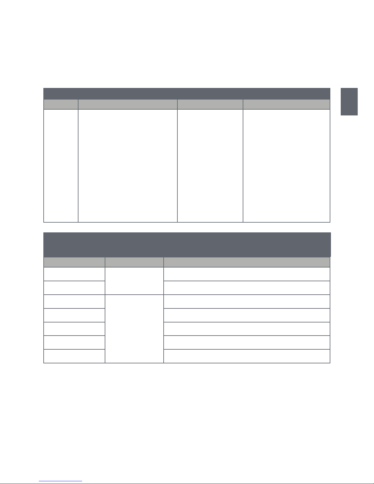
Components
The WM20 is made up of the following components:
Module Description
WM20 Main unit, measures and displays main electrical variables.
With LCD display and touch keypad, it lets you set
PHDVXUHPHQWSDUDPHWHUVFRQ¿JXUHDFFHVVRU\PRGXOHVDQG
manageup to two alarms.
Digital outputs Accessory module with two digital outputs. Expands main unit
FDSDFLW\VSHFL¿FDOO\DOORZLQJ\RXWR
transmit pulses proportional to energy consumption
control digital outputs (static or relay according to the module)
Communication Accessory module that lets you transmit data to other systems or
FRQ¿JXUHWKHDQDO\]HUIURPUHPRWH
9
EN
8021572 | WM20 | © 2016 | CARLO GAVAZZI Controls SpA
Breakdown of code key of main unit (rear of unit)
WM20 AVx 3 a
Model AV4: From 380 to 690 V
L-L ac, 1(2) A, connection
via CT
AV5: From 380 to 690 V
L-L ac, 5(6) A, connection
via CT
AV6: From 100 to 230 V
L-L ac, 5(6) A, connection
via CT
AV7: From 100 to 230 V
L-L ac, 1(2) A, connection
via CT
System:
balanced and
non-balanced
three-phase
with 3 or 4
wires
Two-phase
(3-wire)
Single-phase
(2-wire)
H: auxiliary power
supply from 100 to
240 V ac/dcL: auxiliary
power supply from 24 to
48 V ac/dc
Breakdown of code key of compatible accessory modules
(rear of module)
Code key Type Module description
M O O2
Digital outputs
Double static output
M O R2 Double relay output
M C 485232
Communication
Modbus RTU communication on RS485/RS232
M C ETH Modbus TCP/IP communication on Ethernet
M C BAC IP BACnet IP communication on Ethernet
M C BAC MS BACnet MS/TP communication on RS485
M C PB 3UR¿EXV'39FRPPXQLFDWLRQRQ56

10 8021572 | WM20 | © 2016 | CARLO GAVAZZI Controls SpA
EN
Breakdown of code key of pre-assembled WM20 (rear of main unit)
WM20 AVx 3a aa aa XX
Same as code
key of main
unit,
see "Key to
code key of
the main unit
(rear of unit)"
on page 9
Output type:
XX: none
O2: double
static output
R2: double
relay output
Communication type:
XX: none
S1: RTU Modbus communication on
RS485/RS232
E2: TCP/IP Modbus communication
on Ethernet
B1: BACnet IP communication on
Ethernet
B3: BACnet MS/TP communication
on RS485
P13UR¿EXV'39RQ56
No
option
included
3RVVLEOHFRQ¿JXUDWLRQV
WM20 only WM20 + 1 module WM20 + 2 modules
WARNING:PD[LPXPPRGXOHSHUW\SH,QWKHFRQ¿JXUDWLRQZLWKPRGXOHVWKH
communication module is installed last.
Other manuals for WM20
1
Table of contents


