Carpet Care Systems Trinity OP User manual

Trinity CM
Owners Manual
Carpet Care Systems

Table of Contents
Table of contents 2
Operation and Care 3
Grounding Instructions 3
Warnings 3
Maintenance of Machine 4
Machine Specifications 4
Wiring Instructions 4
Parts list and Diagram 5
Sprayer Hookup Instructions, Handle assembly 6
Warranty 7
Changing the speeds for your Trinity 8
Page 2

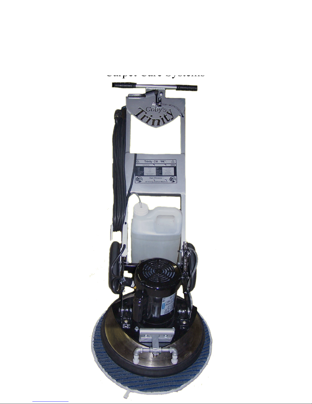
Operation and care Instruction
For the Trinity OP machine.
This floor machine is a high quality, precision made product. All parts used in the manufacturing of this machine have
passed rigid quality control standards prior to assembly and an “each unit” final inspection prior to packaging is your
assurance of proper assembly. This machine was protectively packed to prevent possible damage in transit. Should
damage occur, please notify the transporting carrier immediately for loss and/or claim.
GROUNDING INSTRUCTIONS
This appliance must be grounded. If it should malfunction or break-
down, grounding provides a path of least resistance for electric
current to reduce the risk of electric shock. This appliance is
equipped with a cord having equipment grounding conductor and
grounding plug. The plug must be inserted into an appropriate outlet
that is properly installed and grounded in accordance with all local
codes and ordinances.
Improper connection of the equipment grounding conductor
can result in a risk of electric shock. Check with a qualified
electrician or service person if you are in doubt as to weather
the outlet is properly grounded.
Do not modify the plug provided with the appliance – if it will
not fit the outlet, have a proper outlet installed by a qualified
electrician. Warranty is voided by removal of grounding pin.
This appliance is for use on a nominal 120- Volt circuit, and has a grounded
plug that looks like the plug illustrated in sketch A below. A temporary
adapter that looks like the adapter illustrated in sketches B and C may be
used to connect this plug to a 2-pole receptacle as shown in sketch B if a
properly grounded receptacle is not available. The temporary adapter
should be used only until a properly grounded outlet (sketch A) can be in-
stalled by a qualified electrician. The green colored ear, lug, or the like ex-
tending from the adapter must be connected to a permanent ground such
as a properly grounded outlet box cover. Whenever the adapter is used,
it must be held in place by a metal screw.
NOTE: In Canada, the use of a temporary adapter is not permitted
by the Canadian Electrical Code.
Minimum Wire Size (AWG) f
Extension Cord Usage Chart
Total Extension Cord Length (Feet)
Rating-Amps 25 50 75 100 125 150 175 200
0-10.0 18 18 16 16 14 14 12 12
10.1-13.0 16 16 14 14 14 12 12 12
13.1-15.0 12 12 12 12 12 12 12 –
RISK OF FIRE: Do not use with a flammable or
Combustible liquid to clean a floor
Risk of explosion. Floor sanding can result in an explosive
mixture of fine dust and air. Use floor-sanding machine
only in a well ventilated area free from any flame or match.
DANGER means: Severe bodily injury or death can occur to you
or other personnel if the DANGER statements found on this ma-
chine or in this Owner's Manual are ignored or are not adhered to.
Read and observe all DANGER statements found in this Owner's
Manual and on your machine.
WARNING means: Injury can occur to you or to other personnel
if the WARNING statements found on your machine or in this Own-
er's Manual are ignored or are not adhered to. Read and observe all
WARNING statements found in this Owner's Manual and on your
machine.
CAUTION means: Damage can occur to the machine or to other
property if the CAUTION statements found on your machine or in
this Owner's Manual are ignored or are not adhered to. Read and
observe all CAUTION statements found in this Owner's Manual and
on your machine.
DANGER: Failure to read the Owner's Manual prior to operating or
attempting any service or maintenance procedure to your machine
could result in injury to you or to other personnel; damage to the ma-
chine or to other property could occur as well.
DANGER: To reduce the risk of fire, use only commercially available
carpet products intended for machine application.
DANGER: Risk of explosion. Floor sanding can result in an explo-
sive mixture of fine dust and air. To reduce risk of explosion, use as
floor sanding machine only in well ventilated area.
DANGER: Operating a machine that is not completely or fully as-
sembled could result in injury or property damage. Do not operate
this machine until it is completely assembled. Inspect the machine
carefully before operation.
DANGER: Electrocution could occur if maintenance and repairs are
performed on a unit that is not disconnected from the power source.
Disconnect the power supply before attempting any maintenance
or service.
DANGER: Using a machine with a damaged power cord could result
in an electrocution. Do not use the machine if the power cord is
damaged. Do not use the electrical cord to move the machine.
Page 3

WARNING: Maintenance and repairs performed by unauthorized per-
sonnel could result in damage or injury. Keep adjustments according to
specifications.
WARNING: Electrical components of this machine can "short-out" if ex-
posed to water or moisture. Keep the electrical components of the ma-
chine dry. Wipe the machine down after each use. For storage,
keep the machine in a dry building.
WARNING: To prevent damage to the power cord, do not let the brush,
pad, pad driver or wheels touch the power cord when the machine is run-
ning. Always lift the cord over the machine. Do not pull the power cord to
move the machine.
WARNING: Operating a machine without observing instructional infor-
mation could result in injury or damage. Read manual before attempting to
operate.
WARNING: Use of this machine as a step or furniture could result in in-
jury or damage. Do not use this machine as a step or furniture. Do not ride
on this machine.
WARNING: To avoid injury keep hands, feet and loose clothing away
from all moving parts of this machine.
WARNING: Water solutions or cleaning materials used with this type of
machine can leave wet areas on the floor surface. These areas can
cause a dangerous condition for the operator or other persons. Always put
CAUTION signs near the area being cleaned.
CAUTION: The machine is heavy. Use care in transporting it.
Maintenance of the Machine
Clean your machine frequently. It will have longer life and need fewer
repairs. Replace damaged or worn parts with the correct CCS parts.
Keep nuts and bolts tight, if you hear or feel a rattling, examine the han-
dle bolts and be sure they are tight, loose bolts on an oscillating machine
can cause premature and undue wear.
Remove or blow dust and dirt from the motor frequently.
Machine Specifications
Page 4
Model Trinity OP 18” 3 Speed
Voltage 115/240 V 60 hz
Power Cord 12/3 50’
Motor 1 HP 143t Frame
RPM 1800 RPM
Machine Weight 110 #’s With Spray
Wiring Instructions
Simply plug the 12/3 wire male into the 12/3 wire female
connector.
Attach handle by inserting the four bolts, 2 per
side, through the base plate and tighten the the
3/8 nuts with a 9/16 wrench.
Make sure the motor plate is moved forward
away from the handle as far as it can go, or to
put it another way, make sure the handle arms
are moved to the “back” of the motor plate.
Attaching handle to base
Insert 3/8 plastic hose into the slot in the base plate, pull
tube through until it fits up into the tube fitting on the
spray heads.

Tr-1011
Tr-1012
Alum Spacer
Bearing Ring
20
21
Tr-1013
Tr-1014
Motor Mount
Counter-Balance
22 Tr-1015 Weights
23 Tr-1016 Shurflo Pump
24
25
26
Tr-1018
Tr-1019
Tr-1020
Cord Grip
Handle grips
CB-MM bolts
Page 5
5 TrH-1105 Trinity Handle Complete
6 TrH-1106 50’ 12/3 blue/black cord
7 TrH-1107 Push Button for spray
8 TrH-1108 Round Rocker Switch
9 Tr-1001 1 HP Motor
10 Tr-1002 Rubber Bumper
Brushes and heads for the trinity machine.
Brush Head
Grout and Tile Head
Rug Beater Head
14 Tr-1006 Black Phenoi Ball, For Rug Beater
15 Tr-1007 10” ”x2” Balloon cushion wheel
16 Tr-1008 150-997 6208-ZZ Bearing
17 Tr-1009 Alum Center Plug
18
19

Page 5
Page 6
To operate sprayer, either pull up on the lever on the left or press down with your right thumb on
the other end of the lever.
To raise or lower handle, simply pull up on the handle on the right.

Carpet Care Systems U.S. WARRANTY
This Carpet Care Systems Int. Industrial/Commercial Product is warranted to be
free from defects in materials and workmanship under normal use and service for
a period of one year from the date of purchase, when operated and maintained in
accordance with Carpet Care Systems Int.'s Maintenance and Operations In-
structions.
This warranty is extended only to the original purchaser for use of the product. It
does not cover normal wear parts such as electrical cable, rubber parts,
hoses,motor brushes and, wheels.
If difficulty develops with the product, you should:
(a). Contact the Carpet Care Systems Int. @ 859-744-5332
7980 Mt. Sterling Road, Winchester, Ky. 40391
(b). Return the product to the nearest Carpet Care Systems Int. repair location. Transportation charges to
and from the repair location must be prepaid by the purchaser.
(c).Carpet Care Systems Int.will repair the product and or replace any defective parts without charge within
a reasonable time after receipt of the product.
Carpet Care Systems Int.’s liability under this warranty is limited to repair of the product and/or replacement
of parts and is given to purchaser in lieu of all other remedies, including INCIDENTAL AND CONSEQUEN-
TIAL DAMAGES.
THERE ARE NO EXPRESS WARRANTIES OTHER THAN THOSE SPECIFIED HEREIN. THERE ARE NO
WARRANTIES WHICH EXTEND BEYOND THE DESCRIPTION OF THE FACE HEREOF. NO WARRAN-
TIES, INCLUDING BUT NOT LIMITED TO WARRANTY OF MERCHANTABILITY, SHALL BE IMPLIED. A
warranty registration card is provided with your Carpet Care Systems Int. product. Return the card to assist
Carpet Care Systems Int. in providing the performance you expect from your new OP machine. Send to:
Carpet Care Systems Int. @
7980 Mt. Sterling Road, Winchester, Ky. 40391
Page 7

To attach your brush or any head,
use the handy head tool with the
allen tool to hold the center plug as
you insert and tighten the two 3/8
bolts into your counterbalanc,Pic A.
Put the head tool into one of the
holes of the centerplug, Push in two
bolts and start then by hand, then
use the allen tool to tighten them, as
in picutre B
The speed of your Trinity is set by
which holes you use to attach your
different heads to the counterbal-
ance.
As you can see on the CB is a dia-
gram off which way the blue strip
on the centerplug must be posi-
tioned to run at the speed you want
to.
With the blue strip on the right, you
are in speed, same speed as other
CCS machines but still higher speed
than our competitors.
With the blue strip down, you are in
speed 2 or encap speed. Etc.
With the blue strip on the left, you
Changing the speeds for your Trinity
B
A
Page 8
This manual suits for next models
1
Table of contents
Popular Floor Machine manuals by other brands

Pioneer Eclipse
Pioneer Eclipse Power Glide Operator's manual

Nilfisk-Advance
Nilfisk-Advance FM400 L Instructions for use

Mi-T-M
Mi-T-M AW-7020-8001 Operating instructions and parts list

Mi-T-M
Mi-T-M AW-7020-8007 quick start guide

Numatic
Numatic TWINTEC CABLE TT4055 DAILY MAINTENANCE CHART

Tennant
Tennant F3 Operator and parts manual