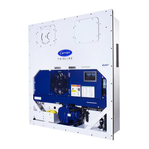
Carrier TRANSICOLD 69NT40-489 Operation manual

i
TABLE OF CONTENTS
Section Page
1DESCRIPTION 1-1........................................................
1.1 Introduction 1-1...........................................................
1.2 General Description 1-10....................................................
1.3 Refrigeration System Data 1-10...............................................
1.4 Electrical Data 1-11.........................................................
1.5 Voltage Switch (Optional) and Power Autotransformer (Optional) 1-11.............
1.6 Refrigeration Circuit 1-12....................................................
1.7 Safety and Protective Devices 1-14............................................
1.8 Fresh Air Makeup Vent 1-14.................................................
1.9 Remote Monitoring (Optional) 1-15..........................................
1.10 Suction Solenoid Valve 1-15..................................................
1.11 Water-Cooled Condenser (Optional) 1-15......................................
1.12 Micro-Link 2 Controller Module 1-16..........................................
1.12.1 Brief Description 1-16..............................................
1.12.2 Controller Programming (Memory) Cards 1-16.........................
1.12.3 General Layout of the Controller Section 1-18..........................
1.12.4 Controller Temperature Control 1-19..................................
1.12.5 Controller Function Codes 1-21......................................
1.12.6 Controller Alarms 1-24..............................................
1.13 Pre-Trip Diagnostics 1-27.....................................................
1.13.1 Pre-Trip 1-28......................................................
1.13.2 Pre-Trip Mode 1-29.................................................
1.14 DataCORDER Module (Optional) 1-32........................................
1.14.1 Brief Description 1-32..............................................
1.14.2 DataCORDER Programming (Memory) Cards 1-33.....................
1.14.3 Functions 1-33.....................................................
1.14.4 Status LED’s 1-35..................................................
1.14.5 DataCORDER Function Codes 1-35..................................
1.14.6 DataCORDER Alarm Codes 1-36....................................
1.14.7 USDA/Message Trip Comment 1-37...................................
1.14.8 USDA Recording 1-37..............................................
1.14.9 Pre-Trip Data Recording 1-38........................................
1.14.10 DataCORDER Communications 1-39.................................
1.15 USDA Cold Treatment Procedure 1-39.........................................
1.16 Humidity Control (Optional) 1-40.............................................
1.17 Nitrogen Feed (Optional) 1-40................................................
2OPERATION 2-1..........................................................
2.1 Pre-Trip Inspection (Before Starting) 2-1......................................
2.2 Starting and Stopping Instructions 2-1........................................
2.3 After Starting Inspection 2-1................................................
2.4 Unit Operation 2-1........................................................
2.4.1 Crankcase Heater (Optional) 2.1....................................
2.4.2 Cooling --- Controller Set BELOW --- 10_C(+14_F) or
--- 5_C(+23_F) optionally 2-1.......................................
2.4.3 Controller Set ABOVE ---10_C(+14_F) or --- 5_C(+23_F) optionally 2-2.
2.4.4 Defrost 2-4.......................................................
2.4.5 Economy 2-5.....................................................
3 TROUBLESHOOTING 3-1.................................................
3.1 UnitWillNotStartorStartsThenStops 3-1...................................
3.2 Unit Runs But Has Insufficient Cooling 3-1....................................
3.3 Unit Operates Long or Continuously In Cooling 3-1............................
3.4 Unit Will Not Heat or Has Insufficient Heating 3-2.............................
3.5 Unit Will Not Terminate Heating 3-2.........................................
3.6 Unit Will Not Defrost Properly 3-2...........................................
Downloaded from ManualsNet.com search engine

ii
TABLE OF CONTENTS (CONTINUED)
Section Page
3.7 Abnormal Pressures (Cooling) 3-3............................................
3.8 Abnormal Noise or Vibrations 3-3............................................
3.9 Temperature Controller Malfunction 3-3......................................
3.10 No Evaporator Air Flow or Restricted Air Flow 3-3.............................
3.11 Thermostatic Expansion Valve Malfunction 3-4.................................
3.12 Power Autotransformer Malfunction 3-4......................................
3.13 Evaporator Motor Transformer Malfunction 3-4................................
3.14 Water-Cooled Condenser or Water Pressure Switch Malfunction 3-4...............
4SERVICE 4-1.............................................................
4.1 Manifold Gauge Set 4-1....................................................
4.2 Suction and Discharge Service Valves 4-3......................................
4.3 Pumping the Unit Down 4-3.................................................
4.4 Refrigerant Leak Checking 4-3..............................................
4.5 Evacuation and Dehydration 4-3.............................................
4.5.1 General 4-3......................................................
4.5.2 Preparation 4-3...................................................
4.5.3 Procedure 4-4....................................................
4.6 Refrigerant Charge 4-4.....................................................
4.6.1 Checking the Refrigerant Charge 4-4.................................
4.6.2 Adding Refrigerant to System (Full Charge) 4-4........................
4.6.3 Adding Refrigerant to System (Partial Charge) 4-4.....................
4.7 Compressor --- Model 06DR 4-6.............................................
4.8 Compressor Disassembly 4-7................................................
4.9 Compressor Reassembly 4-9.................................................
4.10 Compressor Oil Level 4-10...................................................
4.11 Moisture-Liquid Indicator 4-11...............................................
4.12 Filter-Drier 4-11............................................................
4.13 High Pressure Switch 4-11....................................................
4.13.1 Replacing High Pressure Switch 4-11..................................
4.13.2 Checking High Pressure Switch 4-12...................................
4.14 Evaporator Coil and Heater Assembly 4-12.....................................
4.15 Evaporator Fan and Motor Assembly 4-12......................................
4.16 Evaporator Coil Heaters 4-13.................................................
4.17 Condenser Coil 4-13........................................................
4.18 Condenser Fan and Motor Assembly 4-13......................................
4.19 Recording Thermometer (Partlow) 4-13........................................
4.20 Recording Thermometer (Saginomiya) 4-15.....................................
4.21 Maintenance of Painted Surfaces 4-15.........................................
4.22 Power Autotransformer (Optional) 4-16........................................
4.23 SensorCheckoutProcedure(AMBS,DTS,RRS,RTS,SRS&STS) 4-16............
4.23.1 Checking Sensor (RRS, RTS, SRS or STS) 4-16.........................
4.23.2 Replacing Sensor (RRS, RTS, SRS or STS) 4-16........................
4.23.3 Checking Sensor (AMBS or DTS) 4-17................................
4.23.4 Replacing Sensor (AMBS or DTS) 4-17................................
4.24 Suction Solenoid Valve 4-17..................................................
4.25 Suction Modulation Valve 4-18...............................................
4.26 Thermostatic Expansion Valve 4-19............................................
4.27 Evaporator Fan Motor Capacitors (Optional) 4-20...............................
4.28 Controller and DataCORDER 4-21...........................................
4.28.1 Controller Programming Procedure 4-22...............................
4.28.2 DataCORDER Programming Procedure 4-23..........................
4.28.3 Controller Trouble-Shooting 4-23.....................................
4.29 Water-Cooled Condenser 4-24................................................
5 ELECTRICAL WIRING SCHEMATIC AND DIAGRAMS 5-1....................
5.1 Introduction 5-1...........................................................
Downloaded from ManualsNet.com search engine

iii
LIST OF ILLUSTRATIONS
Figure Page
1-1 Refrigeration Unit --- Front 1-4..............................................
1-2 Refrigeration Unit --- Rear (Panels Removed) 1-5...............................
1-3 Receiver and Tubing Section 1-6.............................................
1-4 Control Box --- Prior to Serial # 90234597 1-7..................................
1-5 Control Box --- Starting with Serial # 90234597 1-8..............................
1-6 Power Autotransformer Options 1-9..........................................
1-7 Refrigeration Circuit 1-13....................................................
1-8 Micro-Link 2 Controller Module 1-16..........................................
1-9 Key Pad 1-18...............................................................
1-10 Display Module 1-19........................................................
1-11 DataCORDER Module 1-32.................................................
1-12 Standard Configuration Report Sample 1-41....................................
1-13 Controller Set Point BELOW ---10_C(+14_F) or --- 5_C(+23_F) optionally 1-42.....
1-14 Controller Set Point ABOVE ---10_C(+14_F) or --- 5_C(+23_F) optionally 1-42.....
2-1 Cooling 2-2...............................................................
2-2 Heating Mode 2-3.........................................................
2-3 Defrost 2-4...............................................................
2-4 Economy Mode 2-5........................................................
4-1 Manifold Gauge Set 4-1....................................................
4-2 R-134a Manifold Gauge Set Connections 4-2...................................
4-3 Suction or Discharge Service Valve 4-3........................................
4-4 Vacuum Pump Connections 4-5..............................................
4-5 Compressor --- Model 06DR 4-6.............................................
4-6 Oil Pump 4-6..............................................................
4-7 Exploded View of Valve Plate 4-7............................................
4-8 Bottom Plate Removed 4-7..................................................
4-9 Oil Pump and Bearing Head 4-8.............................................
4-10 Motor End Cover 4-8.......................................................
4-11 Crankshaft Assembly 4-8....................................................
4-12 Removing Equalizing Tube and Lock Screw Assembly 4-9........................
4-13 Terminal Mounting Assembly 4-9.............................................
4-14 Suction Valve and Positioning Springs 4-9.....................................
4-15 Piston Rings 4-9...........................................................
4-16 Compressor Pump End View 4-10.............................................
4-17 Typical Setup for Testing High Pressure Switch 4-12..............................
4-18 Evaporator Fan Locating Dimension 4-12......................................
4-19 Partlow Recording Thermometer 4-14..........................................
4-20 Saginomiya Recording Thermometer 4-15......................................
4-21 Sensor (RRS, RTS, SRS & STS) 4-16..........................................
4-22 Sensor and Cable Assembly (RRS, RTS, SRS & STS) 4-17........................
4-23 Sensor (AMBS or DTS) 4-17.................................................
4-24 Sensor and Wire Assembly (AMBS or DTS) 4-17................................
4-25 Suction Solenoid Valve --- Alco 4-18...........................................
4-26 Suction Modulation Valve 4-18...............................................
4-27 Thermostatic Expansion Valve --- Alco 4-19.....................................
4-28 Thermostatic Expansion Valve Bulb 4-20.......................................
4-29 Controller side of the Control Box 4-21........................................
4-30 Water-Cooled Condenser Cleaning --- Forced Circulation 4-25.....................
4-31 Water-Cooled Condenser Cleaning --- Gravity Circulation 4-25....................
4-32 R-134a Compressor Pressure---Temperature and Motor Current Curves 4-30.........
Downloaded from ManualsNet.com search engine

iv
LIST OF ILLUSTRATIONS (CONTINUED)
Figure Page
5-1 Electrical Schematic --- Models 69NT40-489,-489-11 &
(Model 69NT40-489-1 --- Prior to Serial # 90234597)5-2........................
5-2 Electrical Wiring Diagram --- Models 69NT40-489,-489-11 &
(Model 69NT40-489-1 --- Prior to Serial # 90234597)5-4........................
5-3 Electrical Schematic --- Model 69NT40-489-2 5-6...............................
5-4 Electrical Wiring Diagram --- Model 69NT40-489-2 5-8..........................
5-5 Electrical Schematic --- Model 69NT40-489-10 &
(Model 69NT40-489-3 --- Prior to Serial # 90234597)5-10........................
5-6 Electrical Wiring Diagram --- Model 69NT40-489-10 &
(Model 69NT40-489-3 --- Prior to Serial # 90234597)5-12........................
5-7 Electrical Schematic --- Models 69NT40-489-4,-489-7, -489-8, -489-29 &
(Model 69NT40-489-13 --- Prior to Serial # 90234597)5-14.......................
5-8 Electrical Wiring Diagram --- Models 69NT40-489-4,-489-7, -489-8, -489-29 &
(Model 69NT40-489-13 --- Prior to Serial # 90234597)5-16.......................
5-9 Electrical Schematic --- Models 69NT40-489-5,-489-9 --- Prior to Serial # 90234597 5-18
5-10 Electrical Wiring Diagram --- Models 69NT40-489-5,-489-9 --- Prior to Serial # 90234597 5-20
5-11 Electrical Schematic --- Model 69NT40-489-6,-489-75 5-22.........................
5-12 Electrical Wiring Diagram --- Model 69NT40-489-6,-489-75 5-24...................
5-13 Electrical Schematic --- Model 69NT40-489-12 --- Prior to Serial # 90234597 5-26.....
5-14 Electrical Wiring Diagram --- Model 69NT40-489-12 --- Prior to Serial # 90234597 5-28...
5-15 Electrical Schematic --- Model 69NT40-489-12 --- Starting with Serial # 90234597 5-30....
5-16 Electrical Wiring Diagram --- Model 69NT40-489-12 --- Starting with Serial # 90234597 5-32
5-17 Electrical Schematic --- Models 69NT40-489-17,-489-23,-489-25,-489-59,-489-61,-489-64,
-489-66,-489-67,-489-70,-489-71 &
(Model 69NT40-489-13 --- Starting with Serial # 90234597)5-34.....................
5-18 Electrical Wiring Diagram --- Models 69NT40-489-17,-489-23,-489-25,-489-59,-489-61,-489-64,
-489-66,-489-67,-489-70,-489-71 &
(Model 69NT40-489-13 --- Starting with Serial # 90234597)5-36.....................
5-19 Electrical Schematic --- Model 69NT40-489-26,-489-52,-489-60 &
(Model 69NT40-489-1 --- Starting with Serial # 90234597)5-38.....................
5-20 Electrical Wiring Diagram --- Model 69NT40-489-26,-489-52,-489-60 &
(Model 69NT40-489-1 --- Starting with Serial # 90234597)5-40
5-21 Electrical Schematic --- Model 69NT40-489-3 --- Starting with Serial # 90234597 5-42.....
5-22 Electrical Wiring Diagram --- Model 69NT40-489-3 --- Starting with Serial # 90234597 5-44
5-23 Electrical Schematic --- Models 69NT40-489-14,-489-15,-489-18,-489-21,-489-54,-489-56
-489-58,-489-63,-489-65,-489-68,-489-77,-489-79,-489-83 &
(Model 69NT40-489-5,-489-9 --- Starting with Serial # 90234597)5-46................
5-24 Electrical Wiring Diagram --- Models 69NT40-489-14,-489-15,-489-18,-489-21,-489-54,-489-56
-489-58,-489-63,-489-65,-489-68,-489-77,-489-79,-489-83 &
(Model 69NT40-489-5,-489-9 --- Starting with Serial # 90234597)5-48................
5-25 Electrical Schematic --- Model 69NT40-489-19 5-50..................................
5-26 Electrical Wiring Diagram --- Model 69NT40-489-19 5-52.............................
5-27 Electrical Schematic --- Models 69NT40-489-20E,-489-20M,-489-22 5-54..................
5-28 Electrical Wiring Diagram --- Models 69NT40-489-20E,-489-20M,-489-22 5-56.............
5-29 Electrical Schematic --- Model 69NT40-489-50 5-58..................................
5-30 Electrical Wiring Diagram --- Model 69NT40-489-50 5-60.............................
5-31 Electrical Schematic --- Models 69NT40-489-51,-489-69,-489-81,-489-84 5-62...............
5-32 Electrical Wiring Diagram --- Models 69NT40-489-51,-489-69,-489-81,-489-84 5-64..........
5-33 Electrical Schematic --- Model 69NT40-489-62 5-66..................................
5-34 Electrical Wiring Diagram --- Model 69NT40-489-62 5-68.............................
5-35 Electrical Schematic --- Model 69NT40-489-78 5-70..................................
5-36 Electrical Wiring Diagram --- Model 69NT40-489-78 5-72.............................
5-37 Electrical Schematic --- Model 69NT40-489-80 5-74..................................
5-38 Electrical Wiring Diagram --- Model 69NT40-489-80 5-76.............................
5-39 Electrical Schematic --- Model 69NT40-489-30,-31 5-78...............................
5-40 Electrical Wiring Diagram --- Model 69NT40-489-30,-31 5-80..........................
Downloaded from ManualsNet.com search engine

v
LIST OF TABLES
Table Page
1-1 Model Chart 1-2...........................................................
1-2 Compressor Model Number Significance Chart 1-10.............................
1-3 Safety and Protective Devices 1-14............................................
1-4 Configuration Variables 1-17.................................................
1-5 Key Pad Function 1-18.......................................................
1-6 Controller Function Code Assignments 1-22....................................
1-7 Controller Alarm Indications 1-25.............................................
1-8 Pre-Trip Test Codes 1-28.....................................................
1-9 DataCORDER Function Code Assignments 1-36................................
1-10 DataCORDER Alarm Indications 1-37........................................
1-11 DataCORDER Alarm Configurations 1-37.....................................
1-12 DataCORDER Alarm Pre-Trip Data 1-38......................................
2-1 Electrical Control Positions --- BELOW ---10_C(+14_F) or
--- 5_C(+23_F) optionally 2-6...............................................
2-2 Electrical Control Positions --- ABOVE ---10_C(+14_F) or
--- 5_C(+23_F) optionally 2-6...............................................
4-1 AMBS, DTS, RRS, RTS, SRS & STS Controller and Recorder Sensors
Temperature-Resistance Chart 4-26..........................................
4-2 Partlow Bulb Temperature-Resistance Chart 4-26................................
4-3 Recommended Bolt Torque Values 4-26........................................
4-4 Wear Limits for Compressors 4-27............................................
4-5 Compressor Torque Values 4-28...............................................
4-6 Temperature-Pressure Chart --- R-134a 4-29.....................................
Downloaded from ManualsNet.com search engine
1-1
SECTION 1
DESCRIPTION
1.1 INTRODUCTION
WARNING
It has been determined that pressurized,
air-rich mixtures of refrigerants and air can
undergocombustionwhenexposedtoan
ignition source.
This manual contains Operating Data, Electrical
Data and Service Instructions for the refrigeration units
listed in Table 1-1. Also Table 1-1charts some significant
differences between these models.
The unit, of lightweight aluminum frame
construction, is an all electric, one piece self-contained,
cooling and heating, refrigeration unit. The unit is
designed to fit in the front of a container and to serve as
the container front wall. Fork lift pockets are provided
for installation and removal of the unit.
The unit is complete with a charge of R-134a,
compressor lubricating oil (approved POE SW20
compressor oil for R-134a only), mode indicating lights,
temperature controller and is ready for operation upon
installation.
Some units are dual voltage, designed to operate on
190/230 or 380/460 volts AC, 3 phase, 50-60 hertz power.
(Refertosection1.5)Otherunitsaredesignedtooperate
on 380/460 volts AC, 3 phase 50/60 hertz power only.
Operating control power is provided by a control
transformer which steps down the AC supply power
source to 18 to 24 volts and 30 to 36 voltsAC, 1 phase
control power.
The temperature controller (Micro-Link 2) is a
microprocessor based controller. Refer to section 1.12.
Once the temperature controller is set at a desired
container temperature, the unit will operate
automatically to maintain the desired temperature
withinverycloselimits.Thecontrolsystemautomatically
selects cooling, holding or heating as necessary to
maintain the desired temperature within the container.
WARNING
Beware of unannounced starting of the
evaporator and condenser fans. Do not open the
condenser fan grille before turning power OFF
and disconnecting power plug.
Some units are equipped with a Carrier Transicold
DataCorder (microprocessor based recorder). Detailed
informationontheDataCorderwillbefoundinsection
1.14. Someunitsareequippedwith a Partlowmechanical
temperature recorder or a Saginomiya battery driven
temperature recorder.
Someunitsmay have theintegrated CTDEverFresh
Controlled Atmosphere option installed. Refer to the
Model Chart in Table 1-1. Separately bound manuals
covering the CTD EverFresh Controlled Atmosphere
option are also supplied, see chart below:
Manual
Number Equipment
Covered Type of
Manual
T-265 Controlled
Atmosphere option Operation and
Service
T-265PL Controlled
Atmosphere option Service Parts
List
Some units may have a TransFRESH controlled
atmosphere system added. Contact TransFRESH
Corporation, P.O. Box 1788, Salinas, CA 93902 for
information on their system.
Downloaded from ManualsNet.com search engine
1-2
Table 1-1. Model Chart
NOTE
Models listed below may or may not include certain components (i.e., Transformer, DataCorder, Battery Packs
forthe Controller orDataCorder,TemperatureRecorder), itwillbe upto the end userto ascertainif theirunit
model includes these components.
MODELS
UNIT
WEIGHT R-134a
M
O
D
E
L
S
LB KG LB KG
69NT40-489 1265 573 11.5 5.2 X --- --- X--- X--- --- --- ---
69NT40-489-1 1265 573 11.5 5.2 A --- --- X --- X --- --- --- ---
69NT40-489-2 1265 574 11.5 5.2 --- --- --- --- X --- --- --- --- ---
69NT40-489-3 1385 628 11.5 5.2 A C X --- --- X --- --- H ---
69NT40-489-4 1250 567 11.5 5.2 A --- X --- --- X --- --- --- ---
69NT40-489-5 1385 628 11.5 5.2 A C X --- --- X --- --- --- ---
69NT40-489-6 1310 594 11.5 5.2 --- D X X --- X --- --- --- ---
69NT40-489-7 1230 557 11.5 5.2 A --- X --- --- X --- X --- ---
69NT40-489-8 1235 560 11.5 5.2 X --- X --- --- X --- X --- ---
69NT40-489-9 1385 628 11.5 5.2 A C X --- --- X --- --- --- ---
69NT40-489-10 1385 628 11.5 5.2 A C X --- --- X --- --- I---
69NT40-489-11 1265 573 11.5 5.2 A --- --- X --- X --- --- --- ---
69NT40-489-12 1265 573 11.5 5.2 A --- --- X --- X X --- --- ---
69NT40-489-13 1250 567 11.5 5.2 A B X --- --- X --- --- --- ---
69NT40-489-14 1385 628 11.5 5.2 A C X --- --- X --- --- --- ---
69NT40-489-15 1385 628 11.5 5.2 A C X --- --- X --- --- --- ---
69NT40-489-17 1250 567 11.5 5.2 A B X --- --- X --- --- --- X
69NT40-489-18 1385 628 11.5 5.2 A C X --- --- X --- --- --- ---
69NT40-489-19 1330 603 11.5 5.2 X D X --- --- X X X --- ---
69NT40-489-20E 1550 703 11.5 5.2 X C X X --- X --- --- G ---
69NT40-489-20M 1550 703 11.5 5.2 X --- X X --- X --- X G ---
69NT40-489-21 1385 628 11.5 5.2 --- C X --- --- X --- --- --- ---
69NT40-489-22 1550 703 11.5 5.2 X C X X --- X --- --- G ---
69NT40-489-23 1250 567 11.5 5.2 A B X --- --- X --- --- --- ---
69NT40-489-25 1230 567 11.5 5.2 A B X --- --- X --- --- --- ---
69NT40-489-26 1265 573 11.5 5.2 A --- --- X --- X --- --- --- ---
69NT40-489-29 1250 567 11.5 5.2 A --- X --- --- X --- --- H ---
69NT40-489-30 1250 567 11.5 5.2 A B X --- --- X --- --- --- X
69NT40-489-31 1250 567 11.5 5.2 A B X --- --- X --- --- --- X
69NT40-489-50 1250 567 11.5 5.2 X --- X --- --- X X X H X
69NT40-489-51 1385 628 11.5 5.2 A E X --- --- X --- --- --- ---
69NT40-489-52 1265 573 11.5 5.2 A --- --- X --- X --- --- --- ---
69NT40-489-54 1385 627 11.5 5.2 A C X --- --- X --- --- --- ---
69NT40-489-56 1385 628 11.5 5.2 A C X --- --- X --- --- H ---
69NT40-489-58 1385 628 11.5 5.2 A C X --- --- X --- --- --- ---
69NT40-489-59 1250 567 11.5 5.2 A B X --- --- X --- --- --- ---
69NT40-489-60 1265 573 11.5 5.2 A --- --- --- --- X --- --- --- ---
69NT40-489-61 1220 553 11.5 5.2 --- --- X --- --- X --- --- --- X
69NT40-489-62 1225 556 11.5 5.2 X --- X --- --- X X X H ---
69NT40-489-63 1385 628 11.5 5.2 A C X --- --- X --- --- --- ---
69NT40-489-64 1250 567 11.5 5.2 A B X --- --- X --- --- --- ---
69NT40-489-65 1355 615 9.0 4.1 A B X --- --- X--- --- --- ---
Downloaded from ManualsNet.com search engine
1-3
Table 1-1. Model Chart (Continued)
MODELS
UNIT
WEIGHT R-134a
M
O
D
E
L
S
LB KG LB KG
69NT40-489-66 1250 567 11.5 5.2 X --- X--- --- X--- --- --- X
69NT40-489-67 1235 560 11.5 5.2 X --- X --- --- X --- X --- ---
69NT40-489-68 1385 628 11.5 5.2 A B X --- --- X --- --- --- ---
69NT40-489-69 1385 628 11.5 5.2 A E X --- --- X --- --- H ---
69NT40-489-70 1250 566 11.5 5.2 A B X --- --- X --- --- --- ---
69NT40-489-71 1250 567 11.5 5.2 A B X --- --- X --- --- --- ---
69NT40-489-75 1310 594 11.5 5.2 --- D X X --- X --- --- --- ---
69NT40-489-77 1385 628 11.5 5.2 A C X --- --- X --- --- --- ---
69NT40-489-78 1220 553 11.5 5.2 A --- --- --- --- X --- --- --- ---
69NT40-489-79 1385 628 11.5 5.2 A C X --- --- X --- --- H ---
69NT40-489-80 1330 603 11.5 5.2 A D X X --- X X X --- J
69NT40-489-81 1385 628 11.5 5.2 A E X --- --- X --- --- --- ---
69NT40-489-83 1385 628 11.5 5.2 A B X --- --- X --- --- --- ---
69NT40-489-84 1385 628 11.5 5.2 A E X --- --- X--- --- --- ---
A --- Provision for USDA Cold Treatment.
B --- Provision for Dual Voltage Integral Transformer.
C --- Factory installed Dual Voltage Integral Transformer.
D --- Factory installed Dual Voltage Evaporator Transformer.
E --- Factory installed Dual Voltage Modular Transformer.
F --- Provision for Dual Voltage Modular Transformer.
G --- Factory installed CTD Everfresh Controlled Atmosphere option.
H --- Factory installed Transfresh Controlled Atmosphere option.
I--- Provision for Transfresh Controlled Atmosphere option.
J --- Provision for Communications Interface Module (RMU).
X --- Features that apply to model.
Downloaded from ManualsNet.com search engine
1-4
1
2
3
4
6
78910
11
12
16
1. Access Panel (Evap. Fan Motor #1)
2. Access Panel
(Heater & Thermostatic Expansion Valve Location)
(See Figure 1-2)
3. Fork Lift Pockets
4. Control Box
5. Compressor (CP)
6. Suction Service Valve
7. High Pressure Switch (HPS)
8. Compressor Sight Glass View Port
9. Serial/Model No. Plate
10. Power Cable(s) and Plug(s)
11.CondenserFanMotor(CM)
12. Interrogator Connector
13. Fresh Air Makeup Vent
14. Mechanical Recording Thermometer --- Optional
15. TIR Sealing Provisions
16. Access Panel (Evap. Fan Motor #2)
Figure 1-1. Refrigeration Unit --- Front
5
13
14
15
Downloaded from ManualsNet.com search engine
1-5
1. Evaporator Fan Motor #1 (EM1)
2. Thermostatic Expansion Valve
3. Humidity Sensor (HS) --- Optional
4. Return Recorder Sensor (RRS) --- Optional
5. Return Air Temperature Sensor (RTS)
6. Mechanical Recording Thermometer Bulb
7. Evaporator Fan Motor #2 (EM2)
8. Defrost Termination Sensor (DTS)
9. Heater Termination Thermostat (HTT)
10. Evaporator Coil
11. Drain Pan Heater (DPH)
12. USDA Probe Receptacle (PR3)
13. USDA Probe Receptacle (PR1)
14. Interrogator Receptacle (ICR)
15. USDA Probe Receptacle (PR2)
16. Heat Exchanger
17. Defrost Heaters
18. Cargo Probe --- Optional
1
3
4
5
6
7
8
9
10
11 12
13
14
15
16
17
2
18
Figure 1-2. Refrigeration Unit --- Rear (Panels Removed)
Downloaded from ManualsNet.com search engine
1-6
1. Discharge Pressure Regulator Valve
2. Suction Modulation Valve (SMV)
3. Condenser Pressure Control (CPC) --- Optional
4. Suction Solenoid Valve (SSV)
5. Quench Expansion Valve
6. Manual Liquid Line Valve
7. Ambient Temperature Sensor (AMBS)
8. Moisture-Liquid Indicator
9. Filter-Drier
10. Fusible Plug or
Rupture Disc
(if equipped w/Water-Cooled Condenser)
11. Receiver Sight Glasses
12. Receiver (Shown) or Water-Cooled Condenser
13. Supply Air Temperature Sensor (STS)
14. Supply Recorder Sensor (SRS) --- Optional
15. High Pressure Switch (HPS)
15
1
2
3
4
5
6
7
8
9
10
11
12
13
14
Figure 1-3. Receiver and Tubing Section
Downloaded from ManualsNet.com search engine
1-7
1234 5 67
19 18 17 16 13 12 11
1. Heat Contactor (HR)
2. Evaporator Fan Motor Contactor (EF)
3. Circuit Breaker (CB-1) --- 460V
*4. Circuit Breaker (CB-2) --- 230V --- Optional
(See Figure 1-6 for excepted location)
5. Voltage Switch (VS) --- Optional
6. Display Module
7. Slot location for Remote Monitoring Unit
(RMU) --- Optional
8. Controller Module
9. DataCorder Module --- Optional
10. Keypad
11. Start-Stop Switch (ST)
12. Manual Defrost Switch (MDS)
13. Remote Monitoring Receptacle (RM) --- Optional
14. DataCorder Battery Pack --- Optional
15. Controller Battery Pack --- Optional
16.HighVoltageModule(HVM)
17. Control Transformer (TR)
18. Compressor Contactor (C)
19.CondenserFanMotorContactor(CF)
20. Evaporator Fan Motor Contactor (ES)
89 10
14
15
UNITS WITH SINGLE-SPEED EVAPORATOR MOTORS
UNITS WITH DUAL-SPEED
EVAPORATOR MOTORS
20
5
*
Figure 1-4. Control Box --- Prior to Serial Number 90234597
Downloaded from ManualsNet.com search engine
1-8
1. Evaporator Fan Motor Contactor (EF)
2. Circuit Breaker (CB-1) --- 460V
*3. Circuit Breaker (CB-2) --- 230V --- Optional
(See Figure 1-6 for excepted location)
4. Voltage Switch (VS) --- Optional
5. Display Module
6. Slot location for Remote Monitoring Unit
(RMU) --- Optional
7. Controller Module
8. DataCorder Module --- Optional
9. Keypad
10. Start-Stop Switch (ST)
11. Manual Defrost Switch (MDS)
12. Remote Monitoring Receptacle (RM) --- Optional
13. DataCorder Battery Pack --- Optional
14. Controller Battery Pack --- Optional
15.HighVoltageModule(HVM)
16. Control Transformer (TR)
17. Compressor Contactor (C)
18. Heat Contactor (HR)
19.CondenserFanMotorContactor(CF)
20. Evaporator Fan Motor Contactor (ES)
UNITS WITH SINGLE-SPEED EVAPORATOR MOTORS
UNITS WITH DUAL-SPEED
EVAPORATOR MOTORS
20
19 18 17 16 15 14 13 12 11 10
123 45789
6*
Figure 1-5. Control Box --- Starting with Serial Number 90234597
Downloaded from ManualsNet.com search engine

1-9
1. Dual Voltage Integral Transformer --- Optional
2. Dual Voltage Evaporator Transformer --- Optional
3. Dual Voltage Modular Transformer --- Optional
4. Circuit Breaker (CB-2) --- 230V --- Optional
5. 460 VAC Power Receptacle
Dual Voltage Integral Transformer
Dual Voltage Evaporator Transformer
Dual Voltage Modular Transformer
1
2
3
4
5
Figure 1-6. Power Autotransformer Options
Downloaded from ManualsNet.com search engine
1-10
1.2 GENERAL DESCRIPTION
a. Compressor Section
NOTE
Check the compressor Serial/Model Number
plate forCFM displacement, refer to Table 1-2.
The compressor section includes the compressor
(with high pressure switch), optional crankcase heater,
power cable storage compartment, and an optional
transformer (Refer to Table 1-1 and Figure 1-6) whichis
located to the left of the compressor.
NOTE
The dual voltage evaporator transformer is
always on line and supplies 460v to the
evaporator motor contactor, and 230v to the
control transformer.
This section also contains the suction modulation
valve, suction solenoid valve, quench expansion valve,
moisture-liquid indicator, manual liquid line valve,
filter-drier, fusible plug or rupture disc, discharge
pressure regulator valve and optional discharge/suction
pressure transducers.
The supply air temperature sensor (STS), supply
recorder sensor (SRS) and ambient sensor (AMBS) are
located at the right side of the compressor.
Table 1-2. Compressor Model Number
Significance Chart
06DR2419CC1970
1st, 2nd & 3rd DIGIT
06D Hermetic Reciprocal
4th DIGIT
RRefrigeration Duty
6th & 7th DIGIT DISPLACEMENT
41 41CFM
b. Condenser Section
The condensing section consists of a condenser fan
motor, condenser fan and an air-cooled condenser coil.
Whenthe unit is operating, air is pulled in the bottomof
thecoilanddischargeshorizontallyoutthroughthefront
of the condenser fan grille.
c. Evaporator Section
The evaporator section contains the optional
mechanical temperature recordingbulb, return recorder
sensor (RRS), return temperature sensor (RTS),
thermostaticexpansionvalve,evaporatorfanmotorsand
fans (2), evaporator coil and heaters, drain pan and
heater, defrost termination sensor, heat termination
switch, and a heat exchanger. See Figure 1-2 and
Figure 1-3 for sensor location.
The evaporator fans circulate air throughout the
containerbypullingairinthetopoftherefrigerationunit
anddirectingtheairthroughtheevaporatorcoilwhereit
is either heated or cooled, and then discharged out the
bottom of the refrigeration unit into the container.
Some units are equippedwith two-speedevaporator
fan motors. Refer to Table 1-1. When transporting
perishable (chilled) commodities, the fan motors will
normally be in high speed above ---10_C(+14_F) or
--- 5_C(+23_F) optionally. If the unit is equipped with
economymodeanditisturnedon,thefanmotorswillrun
in low speed.
The evaporator coil heaters are accessible by
removing the front, lower access panel. The defrost
termination sensor (DTS) is located on the coil center
tube-sheet and may be serviced by removing the upper
rear, panel or by removing the left front, upper access
panel and reaching through the evaporator fan venturi
AFTER POWER IS TURNED OFF AND POWER
PLUG DISCONNECTED.
d. Control Box
Thecontrolboxincludesthemanualswitches,circuit
breaker(s), contactors, transformers, fuses, keypad,
display module, high voltage module, controller module
and an optional DataCorder module. (See Figure 1-4 or
Figure 1-5).
1.3 REFRIGERATION SYSTEM DATA
a. Compressor --- Motor Assembly
No. of Cylinders: 6
Model: 06DR
Weight (Dry): 260 lb (118 kg)
b. Approved Compressor Oil
Castrol Icematic --- SW20
c. Compressor Oil Charge
3.6 liters (7.6 U.S. pints)
d. Compressor Oil Sight Glass
The oillevelrange shouldbe betweenthe bottomto
1/8 of the sight glass, with the compressor off.
e. Expansion Valve Superheat
Verify at ---18_C(0_F) container box temperature:
3.36 to 4.48_C(6to8_F)
f. Heater Termination Thermostat
Opens: 54 (¦3)_C = 130 (¦5)_F
Closes: 38 (¦4)_C = 100 (¦7)_F
g. High Pressure Switch
Cutout: 25 (¦0.7) kg/cm@= 350 (¦10) psig
Cut-In: 18 (¦0.7) kg/cm@= 250 (¦10) psig
h. Refrigeration Charge
Refer to Table 1-1.
i. Fusible Plug
Melting point: 93_C = (200 _F)
j. Rupture Disc (Used on water-cooled units only)
Bursts at: 35 ±5% kg/cm@= (500 ±5% psig)
k. Unit Weight
Refer to Table 1-1.
Downloaded from ManualsNet.com search engine

1-11
l. Water Pressure Switch (Optional)
Cut-In: 0.5 ¦0.2 kg/cm@(7 ¦3psig)
Cutout: 1.6 ¦0.4 kg/cm@(22 ¦5psig)
1.4 ELECTRICAL DATA
a. Circuit Breaker
CB-1 Trips at: 29 Amps
CB-2 Trips at: 62.5 Amps
b. Compressor Motor
Full Load Amps (FLA): 17.6 Amps @ 460 VAC
(with current limiting set at 21 amps)
(Model 69NT40)
c. Condenser Fan Motor
Bearing Lubrication: Factory lubricated, additional
grease not required.
Full Load Amps: 2.6/1.3 @ 190/380 VAC/50 hz
3,2/1.6 @ 230/460 VAC/60 hz
Horsepower: 0.43/50 hz (0.75/60 hz)
Rotation: CCW when viewed from shaft end.
Speed: 1425/50 hz (1725/60 hz) RPM
Voltage and Frequency:
180 --- 230/360 --- 460 VAC @ 50 hz ¦1.25 hz
200 --- 250/400 --- 500 VAC @ 60 hz ¦1.5 hz
d. Drain Pan Heaters
Number of Heaters: 1
Rating: 750 watts +5 /---10 % @ 460 VAC
Resistance (cold): 285 ¦7.5% ohms nominal
Type: Sheath
e. Evaporator Coil Heaters
Number of Heaters: 4
Rating: 750 watts +5/---10% each @ 230 VAC
Resistance (cold): 66.8 to 77.2 ohms
Ambient: @20_C(68_F)
Type: Sheath
f. Evaporator Fan Motor(s)
Bearing Lubrication: Factory lubricated, additional
grease not required
Full Load Amps:
High Speed: 1.6 @ 380 VAC/50 hz
(2.1 @ 460 VAC/60 hz)
Low Speed: 0.6 @ 380 VAC/50 hz
(0.6 @ 460 VAC/60 hz)
Single Speed Motor: 3.2/1.6 @ 190/380 VAC/50 hz
(0.58/1.0 @ 230/460 VAC/60
hz)
Nominal Horsepower:
High Speed: 0.58 @ 380 VAC/50 hz
(1.0 @ 460 VAC/60 hz)
Low Speed: 0.07 @ 380 VAC/50 hz
(0.12 @ 460 VAC/60 hz)
Single Speed Motor: 0.58 @ 50 hz
(1.0 @ 60 hz)
Rotation:
Evap. Fan Motor #1 (See Figure 1-2):
CW when viewed from shaft end
CCW when viewed from end opposite shaft end
Evap. Fan Motor #2 (See Figure 1-2):
CCW when viewed from shaft end
CW when viewed from end opposite shaft end
Speed:
High Speed: 2850 rpm @50 hz
(3450 rpm @ 60 hz)
Low Speed: 1425 rpm @ 50 hz
(1750 rpm @ 60 hz)
Single Speed Motor: 2850 rpm @ 50 hz
(3450 rpm @ 60 hz)
Voltage and Frequency:
180 --- 230/360 --- 460 VAC @ 50 hz ¦1.25 hz
200 --- 250/400 --- 500 VAC @ 60 hz ¦1.5 hz
g. Fuses
Control Circuit: 15 Amps (F3)
Controller: 5Amps(F1&F2)
DataCorder: 3Amps(F)
h. Compressor Crankcase Heater (CCH) Optional
180 watts @ 460 vac
1.5 VOLTAGE SWITCH (OPTIONAL) AND
POWER AUTOTRANSFORMER (OPTIONAL)
WARNING
Do notattemptto unplug thepower cable before
turning OFF:
1. Start-stop switch (ST).
2. Unit circuit breaker(s), CB-1 and CB-2 (if
equipped).
3. External power source.
4. Make sure the power plugs are clean and dry
before connecting to any power receptacle.
a. Voltage Switch (without Power Autotransformer)
Dual voltage units without a transformer consist
entirely of dual mains voltage rated components that
operatefromboth190/230VACand380/460VACpower.
b. Step-Up Power Autotransformer
(with or without voltage switch)
Thetransformeriseitherthewhole-unittransformer
(item 1 or item 3, Figure 1-6) or the evaporator
transformer (item 2, Figure 1-6). (Also refer to
Table 1-1) The transformer (if equipped) is located
underthecondensercoilontheleft-handsideoftheunit.
The transformer (item 1 or item 3, Figure 1-6)
provides 380/460 VAC, 3 phase, 50/60 hertz power to the
single mains voltage rated components of the unit when
the 230 VAC (black) power cable is connected to a
190/230 VAC, 3 phase power source. The transformer
(item 1) may be permanently installed in the unit (with
accompanying voltage selector switch VS) or exist as a
modular transformer (item 3) added to convert a single
voltage (380/460 VAC) unit to dual voltage capability
(without voltage selector switch VS). The module in
addition to the transformer, includes a 230 VAC cable,
Downloaded from ManualsNet.com search engine

1-12
circuit breaker CB-2, and a receptacle to accept the unit
460 VAC power plug.
The evaporator transformer (item 2) is permanently
installed and provides 380/460 VAC power to single
voltage(two-speed)evaporatorfanmotorswhentheunit
is operated on 190/230 VAC power and alternately
provides 190/230 VAC power to the control transformer
when the unit is operated from 380/460VAC power.The
remaining mains voltage rated components are dual
voltage designsthat operate from both 190/230 VACand
380/460 VAC via the voltage selector switch (VS).
WARNING
Do notattemptto unplug thepower cable before
turning OFF:
1. Start-stop switch (ST).
2. Unit circuit breaker(s), CB-1 and CB-2 (if
equipped).
3. External power source.
4. Make sure the power plugs are clean and dry
before connecting to any power receptacle.
c. To Operate Unit on 190/230 VAC Power Supply
1. Make sure that the start-stop switch (ST, on
control panel) and circuit breaker (CB-2, in the control
box or on the modular transformer) are in position “0”
(OFF).Makesurevoltageswitch(VS,inthecontrolbox)
isinposition230;orif notequippedwitha voltageswitch
(VS), then make sure the 460 VAC power plug is locked
into the receptacle on the modular transformer and
circuit breaker (CB-1, in the control box) is in position
“1” (ON).
2. Plug the 230 VAC (black) cable into a
de-energized 190/230 VAC, 3 phase power source.
Energize thepower source.Set circuitbreaker(CB-2)to
position“1”(ON).Closeandsecurecontrolboxdoorand
thenplacethestart-stopswitch(ST)inposition“1”(ON)
to start the unit.
d. To Operate Unit on 380/460 VAC Power Supply
1. Make sure start-stop switch (ST, on control
panel) and circuit breaker (CB-1, in the control box) are
in position “0” (OFF). Make sure voltage switch (VS, in
the control box, if equipped) is in position 460.
2. Plug the 460 VAC (yellow) cable into a
de-energized 380/460 VAC, 3 phase power source.
Energize the power source. Place circuit breaker (CB-1)
in position “1” (ON). Close and secure control box door
and then place the start-stop switch (ST) in position “1”
(ON) to start the unit.
1.6 REFRIGERATION CIRCUIT
Starting at the compressor, the suction gas is
compressed to a higher temperature and pressure.
When operating with the air-cooled condenser, the
gas flows through the discharge service valve into the
pressure regulator valve that is normally open, however,
the pressure regulator valve may restrict the flow of
refrigerant tomaintain aminimumdischarge pressure of
5kg/cm@(70psig). Refrigerant gas then moves into the
air-cooled condenser. Air flowing across thecoil fins and
tubescoolsthegastosaturationtemperature.By
removing latent heat, the gas condenses to a high
pressure/high temperature liquid and then flows to the
receiver which stores the additional charge necessary for
low temperature operation.
On units equipped with condenser pressure control
(CPC), the condenser fan will cycle off if the condenser
pressureisbelow130psig.Ifthecondenserpressuregoes
above 200 psig, the condenser fan will cycle on.
From the receiver or water-cooled condenser, the
liquid refrigerant continues through the manual liquid
line valve, filter-drier (which keepsrefrigerant clean and
dry), a moisture-liquid indicator, a heat exchanger that
increases subcooling of liquid refrigerant to the
thermostatic expansion valve. As the liquid refrigerant
passesthroughthe orificeoftheexpansion valve someof
it vaporizes intoa gas (flash gas). Heat is absorbed from
the return air by the balance of the liquid causing it to
vaporize in the evaporator coil. The vapor then flows
through the suction modulation valve (and suction
solenoid valve under some conditions) to the
compressor.
Thethermostaticexpansionvalvebulbonthesuction
line near the evaporator coil outlet, controls the
thermostatic expansion valve, maintaining a relatively
constant superheat at the coil outlet regardless of load
conditions except at abnormally high container
temperatures such as during pulldown (valve at
maximum operating pressure condition).
Downloaded from ManualsNet.com search engine
1-13
1. Suction Service Valve
2. Discharge Service Valve
3. Discharge Pressure Regulator Valve
4. Air-Cooled Condenser
5. Evaporator
6. Thermostatic Expansion Valve
7. External Equalizer Line
8. Thermostatic Expansion Valve Bulb
9. Heat Exchanger
10. Fusible Plug or
Rupture Disc (if equipped w/Water-Cooled
Condenser
11. Manual Liquid Line Valve
12. Moisture-Liquid Indicator
13. Filter-Drier
14. Sight Glass
15. Receiver or
Water-Cooled Condenser
16. Suction Solenoid Valve
17. Suction Modulation Valve
18. Quench Expansion Valve
1
2
34
5
6
7
8
9
11
12
13
14
15
16
17
18
10
Figure 1-7. Refrigeration Circuit
Downloaded from ManualsNet.com search engine
Table of contents
Other Carrier TRANSICOLD Refrigerator manuals

Carrier TRANSICOLD
Carrier TRANSICOLD VECTOR 8100 Installation and operating instructions

Carrier TRANSICOLD
Carrier TRANSICOLD PrimeLINE 69NT40-571-001 Operation manual

Carrier TRANSICOLD
Carrier TRANSICOLD eSolutions Supra 60 Series Guide

Carrier TRANSICOLD
Carrier TRANSICOLD EverFRESH Guide

Carrier TRANSICOLD
Carrier TRANSICOLD Integra 35X Operation manual

Carrier TRANSICOLD
Carrier TRANSICOLD Supra 560 User manual

Carrier TRANSICOLD
Carrier TRANSICOLD 69NT40-541-200 Operation manual

Carrier TRANSICOLD
Carrier TRANSICOLD 69NT40-511-200 Operation manual