i
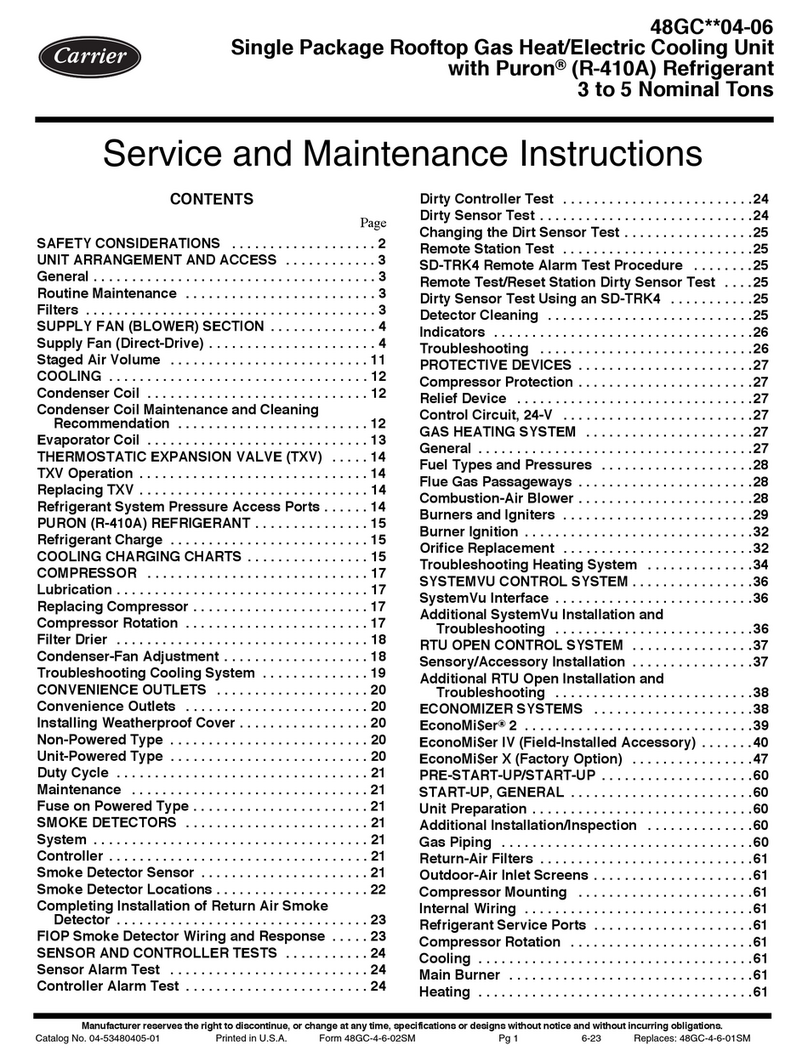
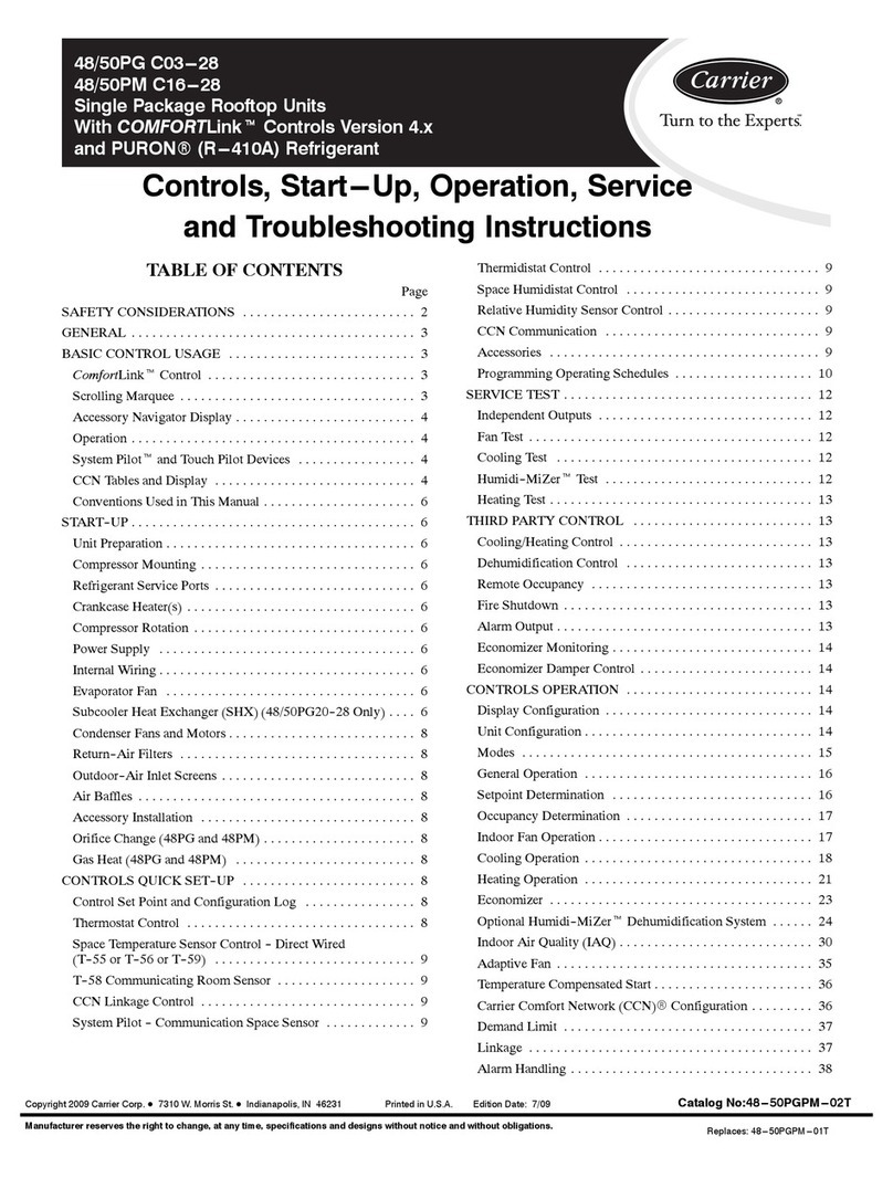
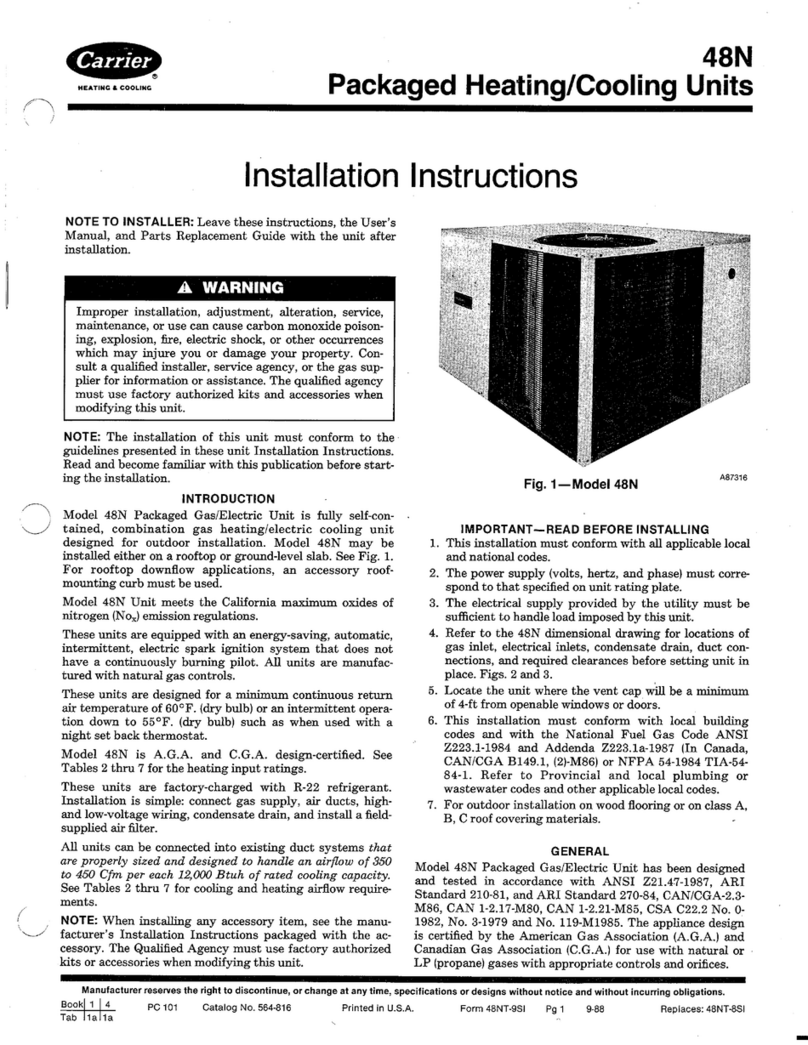
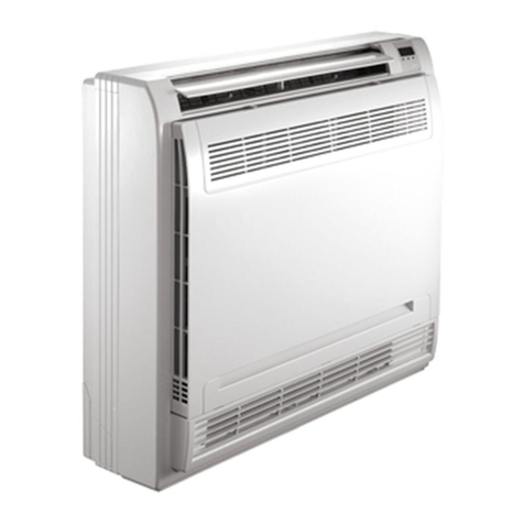
TABLE OF CONTENTS
Section Page
1 DESCRIPTION 1-1.........................................................
1.1 Introduction 1-1............................................................
1.2 Refrigeration System Component Specifications 1-5..............................
1.3 Electrical Specifications 1-6...................................................
1.4 Safety Devices 1-6...........................................................
1.5 System Operating Controls and Components 1-7.................................
1.6 Reheat Coolant Valve 1-9....................................................
1.7 Liquid Line Solenoid Valve 1-9................................................
1.8 Moisture/Liquid Indicator 1-9.................................................
1.9 Heater Coolant Flow Cycle 1-9................................................
1.10 Refrigeration Flow Cycle 1-10..................................................
2OPERATION 2-1...........................................................
2.1 Starting And Stopping Instructions 2-1.........................................
2.2 Pre-Trip Inspection 2-1.......................................................
2.3 Unit Operation 2-1..........................................................
2.3.1 Cooling (Air Conditioning) Cycle Operation - Cycling Clutch Control 2-1...
2.3.2 Cooling (Air Conditioning) Cycle Operation - Reheat Control 2-2..........
2.3.3 Heat Operation 2-3..................................................
3 TROUBLESHOOTING 3-1...................................................
3.1 Unit Will Not Cool 3-1.......................................................
3.2 Unit Runs But has Insufficient Cooling 3-1......................................
3.3 Abnormal Pressure 3-1.......................................................
3.4 Abnormal Noise and Vibrations 3-2............................................
3.4.1 Abnormal Noise 3-2..................................................
3.4.2 Abnormal Vibration 3-2...............................................
3.5 Temperature Controller Malfunction 3-2........................................
3.6 No Evaporator Air Flow or Restricted Air Flow 3-3..............................
3.7 Expansion Valve Malfunction 3-3..............................................
3.8 No Heating or Insufficient Heating 3-3.........................................
4SERVICE 4-1...............................................................
4.1 Maintenance Schedule 4-1....................................................
4.2 Suction and Discharge Service Valves 4-1.......................................
4.3 Manifold Gauge Set 4-1......................................................
4.4 System Pumpdown 4-2.......................................................
4.5 Removing Refrigerant Charge 4-2.............................................
4.6 Refrigerant Leak Check 4-3...................................................
4.7 Evacuation and Dehydration 4-3..............................................
4.8 Adding Refrigerant to System 4-5..............................................
4.9 Checking Refrigerant Charge 4-5..............................................
4.10 Filter-Drier Removal 4-6.....................................................
4.11 Checking Pressure Switches 4-6................................................
4.12 Thermostatic Expansion Valve 4-7.............................................
4.13 Removing the Heater Coil 4-8.................................................
4.14 Replacement of Evaporator Coil 4-8...........................................
4.15 Servicing the Reheat Coolant Valve 4-9.........................................
4.16 Servicing the Liquid Line Solenoid Valve 4-10....................................
