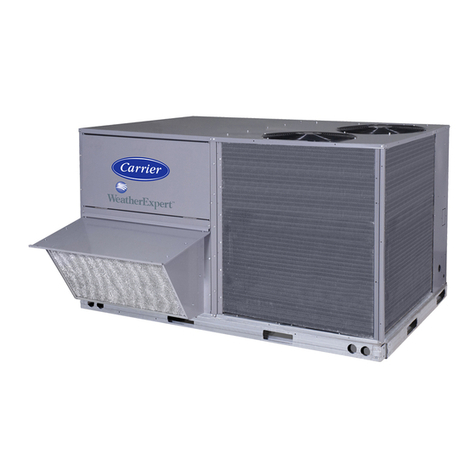
Carrier 09FC020 Installation manual

Manufacturer reserves the right to discontinue, or change at any time, specifications or designs without notice and without incurring obligations.
Catalog No. 04-53090030 -01 Printed in U.S.A. Form 09FC-1SI Pg 1 3-21 Replaces: NEW
Installation, Start-Up and
Maintenance Instructions
CONTENTS
Page
SAFETY CONSIDERATIONS . . . . . . . . . . . . . . . . . . . 1
INTRODUCTION . . . . . . . . . . . . . . . . . . . . . . . . . . . . . . 2
INSTALLATION . . . . . . . . . . . . . . . . . . . . . . . . . . . . . . 6
Storage . . . . . . . . . . . . . . . . . . . . . . . . . . . . . . . . . . . . . 6
• PROVIDE MACHINE PROTECTION
• INSPECTION DURING STORAGE
Step 1 — Inspect Shipment . . . . . . . . . . . . . . . . . . . . 6
Step 2 — Rig and Place Unit . . . . . . . . . . . . . . . . . . . 6
• PLACING UNITS
• MOUNTING UNITS
Step 3 — Connect Chilled Water Loop . . . . . . . . . . 17
• AIR SEPARATION
• FIELD PIPING
• MODULAR UNIT SERIES PIPING (09FC050 - 080)
Step 4 — Fill the Chilled Water Loop . . . . . . . . . . . 21
• WATER SYSTEM CLEANING
• WATER TREATMENT
• FILLING THE SYSTEM
• SET WATER FLOW RATE
Step 5 — Make Electrical Connections . . . . . . . . . . 24
• POWER SUPPLY
• POWER WIRING
• ENABLE SIGNAL
• COMMUNICATION OPTIONS
Step 6 — Install Accessories/Optional Equipment 29
• LOW AMBIENT OPERATION
• FIELD-INSTALLED ACCESSORY INSTALLATION
CONTROLS . . . . . . . . . . . . . . . . . . . . . . . . . . . . . . . . 30
General . . . . . . . . . . . . . . . . . . . . . . . . . . . . . . . . . . . . 30
Control Boards . . . . . . . . . . . . . . . . . . . . . . . . . . . . . 30
Carrier AppController . . . . . . . . . . . . . . . . . . . . . . . . 30
Required Configurations . . . . . . . . . . . . . . . . . . . . . 31
Carrier Equipment Touch Display . . . . . . . . . . . . . . 31
Outdoor Fan Control . . . . . . . . . . . . . . . . . . . . . . . . . 42
• VFD DISPLAY NAVIGATION
• VFD ALARMS AND ALERTS
Field Configuration . . . . . . . . . . . . . . . . . . . . . . . . . . 50
• LEAVING WATER SETPOINT
• OUTDOOR AIR SETPOINT
Communication - BACnet . . . . . . . . . . . . . . . . . . . . . 51
Operation . . . . . . . . . . . . . . . . . . . . . . . . . . . . . . . . . . 53
• SEQUENCE OF OPERATION
• LOW AMBIENT START
• SNOW CLEARING
START-UP . . . . . . . . . . . . . . . . . . . . . . . . . . . . . . . . . 53
SERVICE . . . . . . . . . . . . . . . . . . . . . . . . . . . . . . . . . . 53
Alarms . . . . . . . . . . . . . . . . . . . . . . . . . . . . . . . . . . . . .53
• NON-OPERATIONAL COMPONENT ALARM
• REVERSE LOAD WATER FLOW ALARM
• THERMISTOR ALARM
• FAN VFD FAILURE
Alarm Troubleshooting . . . . . . . . . . . . . . . . . . . . . . .54
• LEAVING WATER TEMPERATURE ALARM
• LEAVING WATER SENSOR FAILURE ALARM
• ENTERING WATER TEMPERATURE ALARM
• ENTERING WATER SENSOR FAILURE ALARM
• OUTDOOR AIR TEMPERATURE ALARM
• OUTDOOR AIR SENSOR FAILURE ALARM
• FAN VFD FAILURE
• REVERSE LOAD WATER FLOW ALARM
Controller Troubleshooting . . . . . . . . . . . . . . . . . . .55
To Restore Defaults . . . . . . . . . . . . . . . . . . . . . . . . . .56
• TO REPLACE THE CONTROLLER’S BATTERY
Fluid Piping System . . . . . . . . . . . . . . . . . . . . . . . . . .56
Check Valve . . . . . . . . . . . . . . . . . . . . . . . . . . . . . . . .56
3-Way Bypass Valve . . . . . . . . . . . . . . . . . . . . . . . . .56
Valve Linkage Adjustment . . . . . . . . . . . . . . . . . . . .56
Thermistor . . . . . . . . . . . . . . . . . . . . . . . . . . . . . . . . .57
External Control Valve . . . . . . . . . . . . . . . . . . . . . . . .57
Replacing Thermistors (EWT, LWT) . . . . . . . . . . . . .57
Replacing Thermistor (OAT) . . . . . . . . . . . . . . . . . . .57
Thermistor/Temperature Sensor Check . . . . . . . . .57
Fan Blade and Fan Motor Service . . . . . . . . . . . . . .59
Round Tube Plate Fin Condenser Coil Cleaning . .60
Remove Surface Loaded Fibers . . . . . . . . . . . . . . . .60
Periodic Clean Water Rinse . . . . . . . . . . . . . . . . . . .60
Routine Cleaning of Coil Surfaces . . . . . . . . . . . . . .60
Totaline Indoor/Outdoor Coil Cleaner Instructions 60
• REQUIRED EQUIPMENT
Application Instructions . . . . . . . . . . . . . . . . . . . . . . 60
Variable Frequency Drives . . . . . . . . . . . . . . . . . . . .61
MAINTENANCE . . . . . . . . . . . . . . . . . . . . . . . . . . . . .61
Recommended Maintenance Schedule . . . . . . . . . .61
Coil Maintenance and Cleaning . . . . . . . . . . . . . . . .61
APPENDIX A —CONTROL PANEL COMPONENT
LAYOUT . . . . . . . . . . . . . . . . . . . . . . . . . . . . . . . . . . .62
APPENDIX B —09FC FREE COOLING MODULE
CONTROLLER . . . . . . . . . . . . . . . . . . . . . . . . . . . . . .63
SAFETY CONSIDERATIONS
Installing, starting up, and servicing this equipment can be hazard-
ous due to system pressures, electrical components, and equip-
ment location (roofs, elevated structures, etc.).
09FC020-080
Free Cooling Unit
50/60 Hz

2
Only trained, qualified installers and service mechanics should in-
stall, start up, and service this equipment.
Untrained personnel can perform basic maintenance functions,
such as cleaning coils. All other operations should be performed
by trained service personnel.
When working on the equipment, observe precautions in the liter-
ature, and on tags, stickers, and labels attached to the equipment
and any other safety precautions that may apply.
• Follow all safety codes.
• Wear safety glasses and work gloves.
• Use care in handling, rigging, and setting bulky
equipment.
INTRODUCTION
This book contains the installation instructions, start-up and ser-
vice information for free cooling units.
See Table 1 for 09FC physical data information. See Fig. 1 for
model number nomenclature. See Tables 2 and 3 and Fig. 2 for
corner weight information.
DANGER
Separate power sources (main and control power circuits) are
used for these units. Be sure both main and control power
circuits are disconnected before servicing. Failure to do so
could result in personal injury from electric shock.
WARNING
Open all remote disconnects before servicing this equipment.
Failure to do so could result in personal injury from electric
shock.
WARNING
The free cooling module is not to be used by children or
persons with reduced physical, sensory, or mental capabilities.
Anyone with lack of experience and knowledge shall have
supervision or have been given instruction.
DANGER
Electrical shock can cause personal injury and death. After unit
power is disconnected, wait at least 20 minutes for the Variable
Frequency Drives (VFD) capacitors to discharge before
opening drive.
CAUTION
This unit uses a microprocessor control system. Do not short or
jumper between terminations on circuit boards or modules;
control or board failure may result.
Be aware of electrostatic discharge (static electricity) when
handling or making contact with circuit boards or module
connections. Always touch a chassis (grounded) part to
dissipate body electrostatic charge before working inside
control center.
Use extreme care when handling tools near boards and when
connecting or disconnecting terminal plugs. Circuit boards can
easily be damaged. Always hold boards by the edges and avoid
touching components and connections.
This equipment uses, and can radiate, radio frequency energy.
If not installed and used in accordance with the instruction
manual, it may cause interference to radio communications. It
has been tested and found to comply with the limits for a Class
A computing device pursuant to International Standard in
North America EN 61000-2/3 which are designed to provide
reasonable protection against such interference when operated
in a commercial environment. Operation of this equipment in a
residential area is likely to cause interference, in which case the
user, at his own expense, will be required to take whatever
measures may be required to correct the interference.
Always store and transport replacement or defective boards in
anti-static shipping bag.

3
Table 1 — Physical Data
UNIT 09FC*020 09FC*030 09FC*040 09FC*050 09FC*060 09FC*070 09FC*080
Shipping Weight, lbs (kg) 3471 (1574) 4946 (2243) 6482 (2940) 8219 (3728) 9694 (4397) 11209 (5084) 12683 (5753)
Operating Weight, lbs (kg) 4288 (1945) 6162 (2795) 8098 (3673) 10251 (4650) 12126 (5500) 14041 (6369) 15915 (7219)
Net Fluid Volume, gal (l) 98 (371) 146 (552) 194 (734) 234 (888) 281 (1062) 340 (1286) 388 (1468)
Nitrogen Shipping Charge 5 psig
Fans and Motors Shrouded Axial Type, Vertical Discharge
Quantity 4 6 8 10 12 14 16
Maximum Speed, rpm (r/s) 1140 (19)
Coils
Type Round Tube/Plate Fin
No. of Coils 4 6 8 10 12 14 16
Drain/Vent Size, in. 1/4 SAE male flare
Piping
Field Connection Size, in. 6666666
Field Connection Type Victaulic-type
Drain/Vent Size, in. 1/4 NPT
Max. Temperature, °F (°C) 100 (37.8)
Max. Pressure, psi (kPa) 300 (2068)
Chassis Dimensions
Length, ft-in. (mm) 8’ 4" (2535) 12’ 3" (3729) 16’ 2" (4923) 20’ 1" (6117) 24’ 0" (7311) 27’ 11" (8505) 31’ 10" (9699)
Width, ft-in. (mm) 7’ 4" (2236)
Height, ft-in. (mm) 8’ 3" (2513)

4
Fig. 1 — Model Number Nomenclature
09FC A 020 6 S - 0 0 - 0 - L
Model Code
09FC
Design Series
Unit Sizes
020
030
040
050
060
070
080
Power Supply (V-Ph-Hz)
1 = 575-3-60
2 = 380-3-60
5 = 208/230-3-60
6 = 460-3-60
9 = 400-3-50
G = 400-3-60
H = 380-3-50
J = 415-3-50
K = 440-3-50
Efficiency Tier
S = Standard Tier
Coil Options
- = Cu Tube/Al Fin
2 = E-coat Cu Tube/Al Fin
Not Used
Not Used
Piping & Valve Options
- = 3-way Valves
Electrical Options
0 = Single Point Power,
Fused Disconnect,
High SCCR
Control Options
- = BACNet
Shipping Options
0 = Coil Covers
1 = Coil Covers, Security Grilles
2 = Coil Covers, Secuirty Grilles, End Hail Guard
3 = Full Hail Guard
9 = Coil Covers, Security Grilles, Skid, Shipping Bag
B = Coil Covers, Security Grilles, Skid, Shipping Bag
C = Coil Covers, Security Grilles, End Hail Guard, Skid, Shipping Bag
D = Full Hail Guard, Skid, Shipping Bag
L = Coil Face Shipping Protection

5
Fig. 2 — Corner Weights
Table 2 — Unit Operating Corner Weights — lbs
UNIT SIZE OPERATING WEIGHT AT CORNER WEIGHTS, LBS
A B C D E F G H
020 991 1137 1006 1154 ————
030 1410 1663 1417 1672 ————
040 955 1105 920 1065 847 862 1162 1182
050 971 1118 965 1111 1340 1429 1605 1711
060 1390 1645 1376 1629 1340 1429 1605 1711
070 1396 1643 1380 1623 912 1084 892 1060
080 941 1088 935 1082 864 1050 891 1084
UNIT SIZE OPERATING WEIGHT AT CORNER WEIGHTS, LBS
I J K L M N O P
070 902 1087 936 1128 ————
080 922 1069 916 1063 884 1069 932 1127
Table 3 — Unit Operating Corner Weights — kg
UNIT SIZE OPERATING WEIGHT AT CORNER WEIGHTS, LBS
A B C D E F G H
020 450 516 456 523 ————
030 639 754 643 758 ————
040 433 501 418 483 384 391 527 536
050 440 507 438 504 608 648 728 776
060 630 746 624 739 608 648 728 776
070 633 745 626 736 414 492 405 481
080 427 494 424 491 392 476 404 492
UNIT SIZE OPERATING WEIGHT AT CORNER WEIGHTS, LBS
I J K L M N O P
070 409 493 424 512 ————
080 418 485 416 482 401 485 423 511
ACE GI K
BDFHJL
09FC070 Control
Panel
AC
BD
09FC020
,
09FC030 Control
Panel
ACE GI KM O
BDF HJ LN P
09FC080 Control
Panel
ACE G
BDF H
09FC040, 09FC050, 09FC060
Control
Panel

6
INSTALLATION
Storage
The 09FC free cooling units are designed for outdoor installations.
At times, a delay in construction or other factors require that a unit
be stored for a period of time prior to installation. The following
guidelines should be used for unit storage.
PROVIDE MACHINE PROTECTION
Place and store the unit in an area that will protect it from vandal-
ism, accidental contact with vehicles, falling debris or construction
waste. Ideally, do not remove the shipping protection such as the
coil protectors. This will provide additional protection for the unit.
The unit can be stored outdoors.
INSPECTION DURING STORAGE
To ensure faster installation when the time comes, the following
inspection schedule is recommended:
Every 3 Months
The 09FC units are shipped with a nitrogen holding charge in the
water loop. Check to be sure that there is positive pressure, at least
5 psig (34 kPa) in the water piping. If a circuit is found to be with-
out pressure, contact a qualified refrigeration mechanic. The sys-
tem should be pressurized to find the leak. It should be repaired
and recharged with nitrogen.
Every 6 Months
Check the unit for damage, both physical and from wildlife.
Check the unit for nests from rodents, birds, or insects. Depending
on location, these organisms can cause deterioration of compo-
nents which may result in failure. Consider an exterminator if nec-
essary. If damage is found and it will interfere with the installation,
consider repairing the damage before installation. Check the unit
control box for signs of moisture. If moisture is found, determine
the entry path and seal the leak.
Step 1 — Inspect Shipment
Inspect unit for damage upon arrival. If damage is found,
immediately file a claim with the shipping company. Verify proper
unit delivery by checking unit nameplate data and the model
number nomenclature shown in Fig. 1. See Table 1 for unit
physical data.
Step 2 — Rig and Place Unit
All units are designed for overhead rigging, it is important that
this method be used. Lifting holes are provided in frame base rails.
It is recommended shackles are used in the lifting holes (see rig-
ging label on unit and Fig. 4 for rigging weights and center of
gravity). All panels must be in place when rigging.
Use spreader bars or frame to keep the cables, chains, and straps
clear of the unit sides. Leave standard coil protection packaging in
place during rigging to provide coil protection. Remove and dis-
card all coil protection after rigging cables are detached.
Standard 09FC unit packaging consists of coil protection only.
Skids are not provided unless selected as a shipping option. If
overhead rigging is not available at the jobsite, the unit should be
placed on a skid or pad before dragging or rolling. Units with ex-
port shipping skid option, cannot be moved using rollers unless
there is a way to remove them first. When rolling, use a minimum
of 3 rollers. When dragging, pull the pad or skid. Do not apply
force to the unit. When in final position, raise from above to lift
unit off the pad or skid.
PLACING UNITS
When considering unit location, be sure to consult National Elec-
trical Code (NEC, U.S.A.) and local code requirements. Allow
sufficient space for airflow, wiring, piping, and service. The place-
ment area must be level and strong enough to support the operat-
ing weight of the unit. (See Tables 2 and 3.)
In areas where snow can be expected, consider the snow depth for
the location. The fan variable frequency drive (VFD) is equipped
with a cooling fan located on the bottom of the device. The unit
should be installed with the inlet of the VFD cooling fan at least
12 in. (304 mm) above the anticipated snow level.
Refer to Fig. 5-11 for airflow clearances. Recommended mini-
mum clearances are 6 ft (1829 mm) for unrestricted airflow and
service on sides of unit, 4 ft (1219 mm) on ends, and unrestricted
clear air space above the unit. Provide ample space to connect flu-
id lines to unit.
For multiple units, allow 10 ft (3048 mm) separation between air-
flow surfaces. See Fig. 3. If walls surround the unit, wall height
should not exceed the top of the unit fan discharge. Installation in
a pit is not recommended.
The unit may be placed at the end (opposite control box) of a
chiller, however assure there is space for piping between water
connections. Some chiller water connections are at the end of the
chiller and may not be accessible if 09FC is too close to it.
Fig. 3 — 09FC Multiple Unit Separation
IMPORTANT: To maintain unit stability while lifting, use a
minimum of 4 cables, chains or straps of equal length.
Attach one end of each cable to shackle attachment point
and the other end of each cable to overhead rigging point.
CAUTION
All panels must be in place when rigging. Failure to comply
could result in equipment damage.
CAUTION
For all unit sizes, do not forklift unit unless unit is attached to a
skid designed for forklifting. Failure to follow this caution
could result in equipment damage or personal injury.
* Minimum for when coils face each other. Less clearance is
required in other configurations.
† Clearance of 3.5 ft is required when a coil faces the wall. When
there is no coil facing the wall, see the certified drawing for the
required service clearance.
10 ft
(3.0 m)
MINIMUM*
3.5 ft (1.1 m)
MINIMUM†

7
Fig. 4 — Rigging Label
1. 1.50 dia (38.1mm) lifting holes provided for field supplied clevis.
2. Rig with a minimum of 25 ft (7620mm) length chain or cables.
3. If central lifting point is used, it must be minimum of 13 ft.
(3962mm) above the top of the unit.
4. Spreader bars made from steel or double nailed, and notched
2x6’s approximately 8 ft. (2438mm) long, must be placed just above
the top of the unit and coils.
5. If overhead rigging is not available, the unit can be moved on
roller or dragged. When unit is moved on roller, the unit steel skid, if
equipped, must be removed.To lift the unit, use jacks at rigging
points. Use a minimum of one roller every 6 ft. (1829mm) to
distribute the load. If the unit is to be dragged, lift the unit as
described above, and place unit on a pad. Apply moving force to the
pad, not the unit. When in its final location, raise the unit and
remove the pad.
6. Check the bill of lading to determine shipping weight of the unit.

8
Fig. 5 — 09FC 020 Unit Dimensions

9
Fig. 6 — 09FC 030 Unit Dimensions

10
Fig. 7 — 09FC 040 Unit Dimensions

11
Fig. 8 — 09FC 050 Unit Dimensions

12
Fig. 9 — 09FC 060 Unit Dimensions

13
Fig. 10 — 09FC 070 Unit Dimensions

14
Fig. 11 — 09FC 080 Unit Dimensions

15
Fig. 11 — 09FC Unit Dimensions
MOUNTING UNITS
When unit is in proper location, use of mounting holes in base
rails is recommended for securing unit to supporting structure.
Fasteners for mounting unit are field supplied. See Fig. 5-11. Be
sure unit is level to within 1/8 in. (3.2 mm) per foot for factory sup-
plied drains to operate properly.
NOTE: For units that are point loaded, such as those using rubber
and shear isolators, the base rail must be supported with a 24 x
4 in. (610 x 102 mm) plate at each mounting location, or base rail
deflection may result. See Fig. 12-15. Fasten the unit to the plates
using the mounting holes.

16
Fig. 12 — 09FC Base Rail Cross Section
Fig. 13 — 09FC Mounting Plate
5.12" [130 mm]
1.42" [36 mm]
5.35" [136 mm]
2.56" [65 mm]
4.87" [124 mm]
2.46" [63 mm]
INNER SIDE
OF UNIT
BASE RAIL
OUTER SIDE
OF UNIT
BASE RAIL
0'– 1-3/4"
[44 mm]
1.50 DIA. [ø38 mm]
RIGGING HOLE
BB
0'– 5"
[127 mm]
0.875 DIA. [ø22 mm]
MOUNTING HOLE
MOUNTING PLATE
0'– 3-15/16"
[100 mm]
0'– 1-9/16"
[39.89 mm]
REF
0'– 7-7/8"
[200 mm]
VIEW B-B
BOTTOM VIEW OF BASE
RAIL AT MOUNTING LOCATION
MOUNTING
PLATE
SIDE VIEW OF BASE RAIL
AT MOUNTING LOCATION
OUTER SIDE OF BASE RAIL

17
Fig. 14 — Perimeter Support Channel
Fig. 15 — Isolator
Step 3 — Connect Chilled Water Loop
Proper system design and installation procedures should be fol-
lowed closely. The system must be constructed with pressure tight
components and thoroughly tested for installation leaks.
Installation of water systems should follow sound engineering
practice as well as applicable local and industry standards.
Improperly designed or installed systems may cause unsatisfacto-
ry operation and/or system failure. Consult a water treatment spe-
cialist or appropriate literature for information regarding filtration,
water treatment, and control devices. Figure 16 show a typical in-
stallation and components.
To facilitate servicing, it is recommended additional field-supplied
air vents be installed. Locate air vents at the highest possible point
of the chilled water systems. To assist with filling and draining the
coils, a vent and drain are located on the top and bottom of each
coil header. Connections are 1/4 in. SAE male flare. In addition to
field-supplied air vents, facilitate servicing in addition to flow bal-
ancing by installing field-supplied shut-off valves, thermometers,
clean-out tees, pressure and temperature taps in the inlet and outlet
piping. Locate valves in return and supply chilled water as close to
the 09FC as possible.
AIR SEPARATION
For proper system operation, it is essential that water loops be in-
stalled with proper means to manage air in the system. Free air in
the system can cause noise, reduce capacity, stop flow, or even
cause pump failure due to pump cavitation. For closed systems,
equipment should be provided to eliminate all air from the system.
The amount of air that water can hold in solution depends on the
pressure and temperature of the water/air mixture. Air is less solu-
ble at higher temperatures and at lower pressures. Therefore, sepa-
ration can best be done at the point of highest water temperature
and lowest pressure. Typically, this point would be on the suction
side of the pump as the water is returning from the system or ter-
minals. This is generally the optimal place to install an air separa-
tor, if possible.
1. Install automatic air vents at all high points in the system. (If
the 09FC unit is located at the high point of the system, a vent
can be installed on the supply piping.)
2. Install an air separator in the water loop, at the place where
the water is at higher temperatures and lower pressures —
usually in the chilled water return piping. On a primary-sec-
ondary system, the highest temperature water is normally in
the secondary loop, close to the de-coupler. Preference should
be given to that point on the system (see Fig. 16). In-line or
centrifugal air separators are readily available in the field.
If it is not possible to install air separators at the place of the high-
est temperature and lowest pressure, preference should be given to
the points of highest temperature. It is important that the pipe be
sized correctly so that free air can be moved to the point of separa-
tion. Generally, a water velocity of at least 2 feet per second (0.6 m
per second) will keep free air entrained and prevent it from form-
ing air pockets.
Automatic vents should be installed at all physically elevated
points in the system so that air can be eliminated during system
operation. Provisions should also be made for manual venting
during the water loop fill.

18
Fig. 16 — Typical Air Separator and Expansion Tank Location on Primary-Secondary Systems
FIELD PIPING
When facing the coil header side of the unit, the inlet (return)
water connection is on the right. It is required that a field-sup-
plied strainer with a minimum size of 20 mesh and blow-down
valve be installed within 10 ft (3.05 m) of the unit connection
to prevent debris from damaging coil tubes. The blow-down
valve allows removal of particulates caught in the strainer
without complete removal of the screen. The outlet (supply)
water connection is on the left.
The 09FC has water-side Victaulic-type connections. Provide
proper support for the piping. If security grilles have been added,
holes must be cut in the grilles for field piping and insulation, if
required.
Victaulic Coupling Installation
1. The outside surface of the pipe, between the groove and the
pipe end, must be smooth and free from indentations, projec-
tions (including weld seams), and roll marks to ensure a leak-
tight seal. All oil, grease, loose paint, and dirt must be
removed.
2. Apply a thin coat of Victaulic lubricant or silicone lubricant to
the gasket sealing lips and exterior.
3. Position the gasket over the pipe end. Make sure the gasket
does not overhang the pipe end.
4. Align and bring the two pipe ends together. Slide the gasket
into position and center it between the groove in each pipe
end. Make sure no portion of the gasket extends into the
groove in either pipe end.
5. Install the housings over the gasket.
NOTE: Make sure the housings' keys engage the grooves
completely on both pipe ends.
6. Install the bolts, and thread a nut finger-tight onto each bolt.
For couplings supplied with stainless steel hardware, apply an
anti-seize compound to the bolt threads. Make sure the oval
neck of each bolt seats properly in the bolt hole.
7. Tighten the nuts evenly by alternating sides until metal-to-
metal contact occurs at the bolt pads. Make sure the housings'
keys engage the grooves completely.
NOTE: It is important to tighten the nuts evenly to prevent
gasket pinching.
8. Visually inspect the bolt pads at each joint to ensure metal-to-
metal contact is achieved.
See Fig. 18-22 for a typical piping diagram of a 09FC unit. Drain
connections are located at the bottom of the entering and leaving
water piping at the end of the unit. See Fig. 5-11 for connection lo-
cation.
The EWT and LWT thermistors are field-installed. See Fig. 17.
The thermistors are supplied with the unit coiled up near the enter-
ing and leaving water connections. Thermowells are included with
the unit and are placed in the control panel. Thermowells are 1/4in.
NPT to be installed in entering and leaving piping. Allow 4 pipe
diameters or straight pipe upstream of thermistor mounting loca-
tion to achieve mix flow for an accurate temperature measure-
ment. See Fig. 18-21 for suggested locations. On larger units,
09FC050-080, the LWT thermowell must be placed in the com-
mon piping if unit is piped in parallel arrangement.
In sound sensitive applications, consider the installation of piping
vibration isolators.
NOTE: Expansion tanks for 30XV/09FC hydronic kits must be installed for chillers piped in parallel in the primary water loop.
Zone 1
Zone 2
Zone 3
Distribution Pump
Air Separator
with Vent
Expansion
Tank(s)
Decoupler
Chiller 1
Chiller 2
09FC
09FC
WARNING
Safely relieve the pressure, and check for zero residual
pressure before removing the caps.
CAUTION
Always use a compatible lubricant to prevent the gasket from
pinching or tearing during installation. Failure to follow this
instruction could result in joint leakage.
CAUTION
Make sure the gasket does not become rolled or pinched while
installing the housings. Failure to follow this instruction could
cause damage to the gasket, resulting in joint leakage.

19
Fig. 17 — Dual Chiller Accessory Kit Leaving Water Thermistor and Well (P/N 00EFN900044000A)
MODULAR UNIT SERIES PIPING (09FC050 - 080)
The modular unit sizes 050 - 080, have two piping systems. From
the factory they are separated for parallel piping in the field. For
low flow rates, less than 150 gpm per V section, the unit may need
to be converted to a series arrangement for improved performance.
This conversion requires joining the two unit connections in the
center of the unit. These are the leaving water connection for the
first circuit and the entering water connection of the second
circuit.
First step is to remove the insulation from these tees. Rotate the
tees at these locations so they point towards each other. Remove
the couplings holding the tees. Reorient the tees so they point to-
wards each other, see Fig. 22. Once the tees are reattached add the
joining pipe include in the Modular Piping Accessory (Part No.
09FC70000801). Attach with the existing couplings. Add insula-
tion back to the tees and joining pipe section.
Fig. 18 — 09FC 050-080 Parallel Piping
30XV 140, 160, 180, 225 Standard Tier, 140 Mid Tier
5/8in. HEX
6 in. MINIMUM
CLEARANCE FOR
THERMISTOR
REMOVAL
1.188 in.
2.315 in.
1/4-18NPT
WIRE TIE
LOOP
THERMISTOR WIRE
AND SECURE
TO CHILLED WATER PIPE
INSERT THERMISTOR UNTIL
O-RING MEETSTHE
THERMISTOR WELL BODY.
09FC Unit Chiller
LWT
(Note 2)
EWT
(Note 2)
36"
(Note 1)
09FC
Control
Panel
24" Min
(Note 3)
NOTES:
1. Allow 36 in. for fan VFD access. Verify 36 in. meets local codes.
2. EWT and LWT thermistors must be installed in the field.
Thermistors are supplied inside control panel. Add 1/4 in. NPT hole in pipe for mounting.
LWT thermistor well must be in mixed flow piping.
3. Minimum access is a recommendation. Local code may require increased spacing.
4. Chiller tube service must be done from control panel end for this arrangement. See chiller
certified drawings for details.

20
Fig. 19 — 09FC 020-040, 050-080 Series Piping
30XV 140, 160, 180, 225 Standard Tier, 140 Mid Tier
Fig. 20 — 09FC 050-080 Series Piping
30XV 200, 250-500 Standard Tier
160-500 Mid Tier
140-500 High Tier
09FC Unit Chiller
LWT
(Note 1)
EWT
(Note 1)
09FC
Control
Panel
24" Min
(Note 2)
NOTES:
1. EWT and LWT thermistors must be installed in the field.
Thermistors are supplied inside control panel. Add 1/4 in. NPT hole in pipe for mounting.
LWT thermistor well must be in mixed flow piping.
2. Minimum access is a recommendation. Local code may require increased spacing.
3. Chiller tube service must be done from control panel end for this arrangement. See chiller
certified drawings for details.
09FC Unit
LWT
(Note 1)
EWT
(Note 1)
09FC
Control
Panel
1" Min
(Note 2)
NOTES:
1. EWT and LWT thermistors must be installed in the field.
Thermistors are supplied inside control panel. Add 1/4 in. NPT hole in pipe for mounting.
LWT thermistor well must be in mixed flow piping.
2. Minimum access is a recommendation. Local code may require increased spacing.
3. Chiller tube service must be done from control panel end for this arrangement. See chiller
certified drawings for details.
Chiller
This manual suits for next models
6
Table of contents
Other Carrier Cooling Box manuals