Carrier 50LC 14 Installation and user guide

Manufacturer reserves the right to discontinue, or change at any time, specifications or designs without notice and without incurring obligations.
Catalog No. 04-53500167-01 Printed in U.S.A. Form 50LC-14-26-03SM Pg 1 2-2020 Replaces: 50LC-14-26-02SM
Service and Maintenance Instructions
CONTENTS
SAFETY CONSIDERATIONS . . . . . . . . . . . . . . . . . . . . 1
General . . . . . . . . . . . . . . . . . . . . . . . . . . . . . . . . . . . . . 2
Routine Maintenance . . . . . . . . . . . . . . . . . . . . . . . . . . 2
SUPPLY FAN (BLOWER) SECTION . . . . . . . . . . . . . . 3
Supply Fan Assembly . . . . . . . . . . . . . . . . . . . . . . . . . 3
Changing Fan Wheel Speed by Changing Pulleys . . 4
COOLING . . . . . . . . . . . . . . . . . . . . . . . . . . . . . . . . . . . 5
Evaporator Coil . . . . . . . . . . . . . . . . . . . . . . . . . . . . . . 5
Coil Maintenance and Cleaning Recommendation. . 5
Evaporator Coil Metering Devices . . . . . . . . . . . . . . . 6
Refrigerant System Pressure Access Ports . . . . . . . 6
PURON® (R-410A) REFRIGERANT. . . . . . . . . . . . . . . 6
Refrigerant Charge. . . . . . . . . . . . . . . . . . . . . . . . . . . . 6
Evacuation . . . . . . . . . . . . . . . . . . . . . . . . . . . . . . . . . . 7
Compressors . . . . . . . . . . . . . . . . . . . . . . . . . . . . . . . 13
Condenser-Fan Adjustment . . . . . . . . . . . . . . . . . . . 13
Troubleshooting Cooling System. . . . . . . . . . . . . . . 13
CONVENIENCE OUTLETS . . . . . . . . . . . . . . . . . . . . . 15
Wet in Use Convenience Outlet Cover. . . . . . . . . . . 15
Duty Cycle. . . . . . . . . . . . . . . . . . . . . . . . . . . . . . . . . . 15
Non-Powered Type. . . . . . . . . . . . . . . . . . . . . . . . . . . 15
Unit-Powered Type. . . . . . . . . . . . . . . . . . . . . . . . . . . 15
Maintenance . . . . . . . . . . . . . . . . . . . . . . . . . . . . . . . . 17
Fuse On Powered Type . . . . . . . . . . . . . . . . . . . . . . . 17
Using Unit-Mounted Convenience Outlets . . . . . . . 17
SMOKE DETECTORS . . . . . . . . . . . . . . . . . . . . . . . . . 17
System . . . . . . . . . . . . . . . . . . . . . . . . . . . . . . . . . . . . 17
Controller . . . . . . . . . . . . . . . . . . . . . . . . . . . . . . . . . . 17
Sensor . . . . . . . . . . . . . . . . . . . . . . . . . . . . . . . . . . . . . 17
Smoke Detector Locations . . . . . . . . . . . . . . . . . . . . 18
FIOP Smoke Detector Wiring and Response. . . . . . 19
Sensor and Controller Tests . . . . . . . . . . . . . . . . . . . 19
Controller Alarm Test Procedure . . . . . . . . . . . . . . . 20
Dirty Controller Test Procedure . . . . . . . . . . . . . . . . 20
Dirty Sensor Test Procedure. . . . . . . . . . . . . . . . . . . 20
Changing the Dirty Sensor Test . . . . . . . . . . . . . . . . 20
To Configure the Dirty Sensor Test Operation . . . . 20
SD-TRK4 Remote Alarm Test Procedure . . . . . . . . . 20
Detector Cleaning . . . . . . . . . . . . . . . . . . . . . . . . . . . 21
Indicators . . . . . . . . . . . . . . . . . . . . . . . . . . . . . . . . . . 21
Resetting Alarm and Trouble Condition Trips . . . . 22
Troubleshooting. . . . . . . . . . . . . . . . . . . . . . . . . . . . . 22
PROTECTIVE DEVICES . . . . . . . . . . . . . . . . . . . . . . . 22
Compressor Protection . . . . . . . . . . . . . . . . . . . . . . . 22
Supply (Indoor) Fan Motor Protection . . . . . . . . . . . 23
Condenser Fan Motor Protection . . . . . . . . . . . . . . . 23
Control Circuit, 24-V . . . . . . . . . . . . . . . . . . . . . . . . . 23
ELECTRIC HEATERS . . . . . . . . . . . . . . . . . . . . . . . . . 23
Single Point Boxes and Supplementary Fuses . . . .24
Safety Devices . . . . . . . . . . . . . . . . . . . . . . . . . . . . . .24
Low-Voltage Control Connections . . . . . . . . . . . . . .25
WIRING DIAGRAMS . . . . . . . . . . . . . . . . . . . . . . . . . .25
PRE-START-UP . . . . . . . . . . . . . . . . . . . . . . . . . . . . . .31
START-UP, GENERAL . . . . . . . . . . . . . . . . . . . . . . . .31
Unit Preparation . . . . . . . . . . . . . . . . . . . . . . . . . . . . .31
Return-Air Filters . . . . . . . . . . . . . . . . . . . . . . . . . . . .31
Outdoor-Air Inlet Screens . . . . . . . . . . . . . . . . . . . . .31
Compressor Mounting . . . . . . . . . . . . . . . . . . . . . . . .31
Internal Wiring. . . . . . . . . . . . . . . . . . . . . . . . . . . . . . .31
Refrigerant Service Ports. . . . . . . . . . . . . . . . . . . . . .31
Compressor Rotation . . . . . . . . . . . . . . . . . . . . . . . . .32
Cooling. . . . . . . . . . . . . . . . . . . . . . . . . . . . . . . . . . . . .32
Heating. . . . . . . . . . . . . . . . . . . . . . . . . . . . . . . . . . . . .32
Ventilation (Continuous Fan). . . . . . . . . . . . . . . . . . .32
RTU Open Control System. . . . . . . . . . . . . . . . . . . . .34
SYSTEMVU™ (FACTORY OPTION). . . . . . . . . . . . . .34
Integrated Staging Control (ISC) Board . . . . . . . . . .34
EconoMi$er® X (Factory Option) . . . . . . . . . . . . . . .36
Staged Air Volume (SAV™) with Variable Frequency
Drive. . . . . . . . . . . . . . . . . . . . . . . . . . . . . . . . . . . . .50
Multi-Speed VFD Display Kit (Field-Installed
Option). . . . . . . . . . . . . . . . . . . . . . . . . . . . . . . . . . .51
FASTENER TORQUE VALUES. . . . . . . . . . . . . . . . . .62
SEQUENCE OF OPERATION . . . . . . . . . . . . . . . . . . .62
General . . . . . . . . . . . . . . . . . . . . . . . . . . . . . . . . . . . .62
Ventilation . . . . . . . . . . . . . . . . . . . . . . . . . . . . . . . . . .63
Cooling. . . . . . . . . . . . . . . . . . . . . . . . . . . . . . . . . . . . .63
Economizer (Optional) . . . . . . . . . . . . . . . . . . . . . . . .63
Low Ambient Cooling Operation down to 40°F
(4°C) . . . . . . . . . . . . . . . . . . . . . . . . . . . . . . . . . . . . .63
Heating. . . . . . . . . . . . . . . . . . . . . . . . . . . . . . . . . . . . .63
6APPENDIX A — MODEL NUMBER
NOMENCLATURE . . . . . . . . . . . . . . . . . . . . . . . . . .64
APPENDIX B — PHYSICAL DATA . . . . . . . . . . . . . . .65
APPENDIX C — FAN PERFORMANCE . . . . . . . . . . .72
START-UP CHECKLIST . . . . . . . . . . . . . . . . . . . . .CL-1
SAFETY CONSIDERATIONS
Installation and servicing of air-conditioning equipment can be
hazardous due to system pressure and electrical components. Only
trained and qualified service personnel should install, repair, or
service air-conditioning equipment.
Untrained personnel can perform basic maintenance functions of
cleaning coils and filters and replacing filters. All other operations
should be performed by trained service personnel. When working
on air-conditioning equipment, observe precautions in the
literature, tags and labels attached to the unit, and other safety
precautions that may apply.
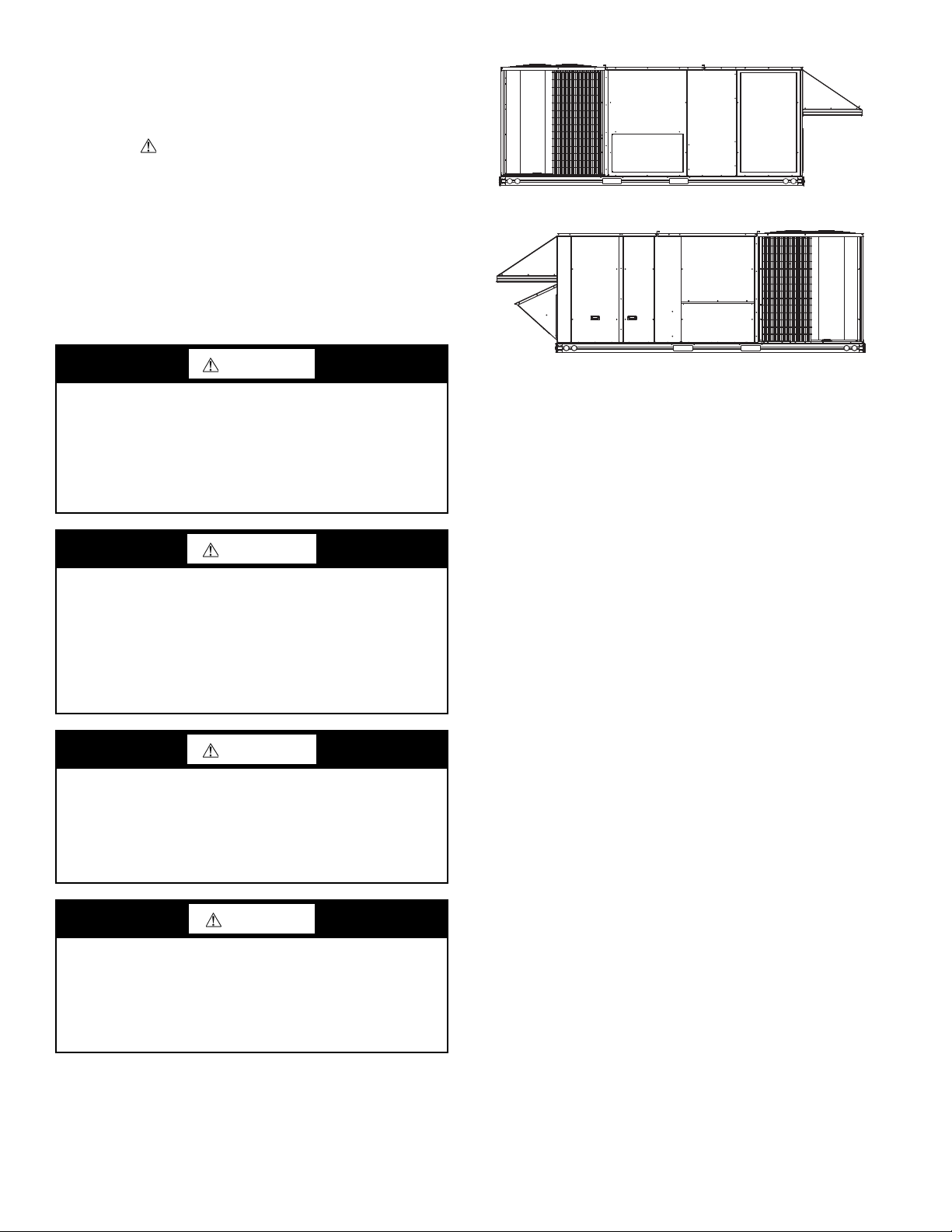
WeatherExpert®
50LC*D14-D26
Single Package Rooftop Cooling Only
with Puron®(R-410A) Refrigerant

2
Follow all safety codes, including ANSI (American National
Standards Institute) Z223.1. Wear safety glasses and work gloves.
Use quenching cloth for unbrazing operations. Have fire
extinguisher available for all brazing operations.
It is important to recognize safety information. This is the safety-
alert symbol . When you see this symbol on the unit and in
instructions or manuals, be alert to the potential for personal
injury.
Understand the signal words DANGER, WARNING,
CAUTION, and NOTE. These words are used with the safety-
alert symbol. DANGER identifies the most serious hazards which
will result in severe personal injury or death. WARNING signifies
hazards which could result in personal injury or death. CAUTION
is used to identify unsafe practices, which may result in minor
personal injury or product and property damage. NOTE is used to
highlight suggestions which will result in enhanced installation,
reliability, or operation.
General
Figure 1 and 2 show general unit arrangement and access
locations.
Fig. 1 — Typical Access Panel Locations (Rear)
Fig. 2 — Typical Access Panel Locations (Front)
Routine Maintenance
These items should be part of a routine maintenance program,
to be checked every month or two, until a specific schedule for
each can be identified for this installation:
QUARTERLY INSPECTION (AND 30 DAYS AFTER INI-
TIAL START)
• Return air filter replacement
• Outdoor hood inlet filters cleaned
• Belt tension checked
• Belt condition checked
• Pulley alignment checked
• Fan shaft bearing locking collar tightness checked
• Condenser coil cleanliness checked
• Condensate drain checked
SEASONAL MAINTENANCE
These items should be checked at the beginning of each season
(or more often if local conditions and usage patterns dictate):
AIR CONDITIONING
• Condenser fan motor mounting bolts tightness
• Compressor mounting bolts
• Condenser fan blade positioning
• Control box cleanliness and wiring condition
• Wire terminal tightness
• Refrigerant charge level
• Evaporator coil cleaning
• Evaporator blower motor amperage
HEATING
• Power wire connections
• Fuses ready
• Manual-reset limit switch is closed
ECONOMIZER OR OUTSIDE AIR DAMPER
• Inlet filters condition
• Check damper travel (economizer)
• Check gear and dampers for debris and dirt
AIR FILTERS AND SCREENS
Each unit is equipped with return air filters. If the unit has an
economizer, it will also have an outside air screen. If a manual
WARNING
ELECTRICAL OPERATION HAZARD
Failure to follow this warning could result in personal inju-
ry or death.
Before performing service or maintenance operations on
unit, LOCKOUT/TAGOUT the main power switch to unit.
Electrical shock and rotating equipment could cause severe
injury.
WARNING
ELECTRICAL OPERATION HAZARD
Failure to follow this warning could result in personal inju-
ry or death.
Units with convenience outlet circuits may use multiple
disconnects. Check convenience outlet for power status be-
fore opening unit for service. Locate its disconnect switch,
if appropriate, and open it. Lock-out and tag-out this
switch, if necessary.
WARNING
UNIT OPERATION AND SAFETY HAZARD
Failure to follow this warning could cause personal injury,
death and/or equipment damage.
R-410A refrigerant systems operate at higher pressures than
standard R-22 systems. Do not use R-22 service equipment or
components on R-410A refrigerant equipment.
CAUTION
PERSONAL INJURY HAZARD
Failure to follow this caution may result in personal injury.
Sheet metal parts may have sharp edges or burrs. Use care
and wear appropriate protective clothing, safety glasses and
gloves when handling parts and servicing air conditioning
equipment.
FILTER
ACCESS
PANEL
ELECTRIC HEAT
ACCESS PANEL
CONTROL
BOX
ACCESS
PANEL
FILTER
AND
INDOOR
COIL
ACCESS
PA N E L
INDOOR
BLOWER
ACCESS
PA N E L

3
outside air damper is added, an inlet air screen
will also be present.
Each of these filters and screens will need to be periodically re-
placed or cleaned.
RETURN AIR FILTERS
Return air filters are disposable fiberglass media type. Access
to the filters is through the vertical panel to the right of the con-
trol box. Filters are situated on slide-out racks for easy inspec-
tion and repair. (See Fig. 1.)
To remove the filters:
1. Remove vertical filter access door.
2. Reach in and extract the filters from the filter rack.
3. Replace these filters as required with similar replacement
filters of same size. Observe the flow direction arrows on
the side of each filter frame.
4. Re-install filter access panel.
OUTSIDE AIR HOOD
Outside air hood inlet screens are permanent aluminum-mesh
type filters. Check these for cleanliness.
Remove the screens when cleaning is required. Clean by wash-
ing with hot low-pressure water and soft detergent and replace
all screens before restarting the unit. Observe the flow direc-
tion arrows on the side of each filter frame.
ECONOMIZER AND MANUAL OUTSIDE AIR SCREENS
This air screen is retained by spring clips under the top edge of
the hood. (See Fig. 3.)
Fig. 3 — Filter Installation
To remove the filter, remove screws in horizontal filter retain-
ers on leading edge of hood. Slide filters out. To re-install fil-
ters, slide clean or new filters into hood side retainers. Once
positioned, re-install horizontal filter retainer.
SUPPLY FAN (BLOWER) SECTION
Supply Fan Assembly
The supply fan system consists of two forward-curved centrif-
ugal blower wheels mounted on a solid blower shaft that is
supported by two greaseable pillow block concentric bearings.
A fixed-pitch driven (fan) pulley is attached to the fan shaft
and an adjustable-pitch driver pulley is mounted on the motor.
The pulleys are connected using a “V” type belt. (See Fig. 4.)
Fig. 4 — Belt Drive Motor Mounting
BELT
Check the belt condition and tension quarterly. Inspect the belt
for signs of cracking, fraying or glazing along the inside sur-
faces. Check belt tension by using a spring-force tool (such as
Browning’s “Belt Tension Checker” or equivalent tool); ten-
sion should be between 5 and 10 lbs with 5/8-in. deflection
when measured at the centerline of the belt span. This point is
at the center of the belt when measuring the distance between
the motor shaft and the blower shaft.
NOTE: Without the spring-tension tool, place a straight edge
across the belt surface at the pulleys, then deflect the belt at mid-
span using one finger to a 1/2-in. deflection.
Adjust the belt tension by loosening the four motor mounting
nuts and bolts where the motor bolts to the blower rail. There
are two jack bolts and nuts that are used to slide the motor plate
to either increase or decrease belt tension. There are locking
nuts on the jack bolts that need to be loosened at the motor
plate. Turn the jack bolts clockwise or counter clockwise until
the correct belt tension is achieved. Ensure the fan shaft and
motor shaft are parallel prior to tightening motor plate nuts.
(See Fig. 5.)
Fig. 5 — Adjusting Belt Tension
IMPORTANT: DO NOT OPERATE THE UNIT WITH-
OUT THESE FILTERS!
WARNING
ELECTRICAL OPERATION HAZARD
Failure to follow this warning could result in personal inju-
ry or death.
Before performing service or maintenance operations on
unit, LOCKOUT/TAGOUT the main power switch to unit.
Electrical shock and rotating equipment could cause severe
injury.
Step 1: Loosen
motor bolts
Step 2: Loosen jack bolt
lock nuts
Step 3: Loosen or tighten
jack boltsuntil proper
belt tension isachieved

4
To replace the belt:
1. Use a belt with same section type or similar size. Do not
substitute a “FHP” type belt. When installing the new belt,
do not use a tool (screwdriver or pry-bar) to force the belt
over the pulley flanges. This will stress the belt and cause
a reduction in belt life.
2. Loosen the motor mounting plate front bolts and rear
bolts.
3. Loosen the Jack bolt lock nuts and using the Jack bolts
relieve the belt tension to allow easy removal of the belt
by hand.
4. Remove the belt by gently lifting the old belt over one of
the pulleys.
5. Install the new belt by gently sliding the belt over both
pulleys, then using the Jack bolts slide the motor plate
away from the fan housing until proper belt tension is
achieved.
6. Check the alignment of the pulleys; adjust if necessary.
7. Tighten all nuts to motor plate and Jack bolts.
8. Check the tension after a few hours of runtime and re-
adjust as required.
ADJUSTABLE-PITCH PULLEY ON MOTOR
The motor pulley is an adjustable-pitch type that allows a ser-
vicer to implement changes in the fan wheel speed to match as-
installed ductwork systems. The pulley consists of a fixed
flange side that faces the motor (secured to the motor shaft)
and a movable flange side that can be rotated around the fixed
flange side that increases or reduces the pitch diameter of this
driver pulley. (See Fig. 6.)
Fig. 6 — Supply-Fan Pulley Adjustment
As the pitch diameter is changed by adjusting the position of
the movable flange, the centerline on this pulley shifts laterally
(along the motor shaft). This creates a requirement for a re-
alignment of the pulleys after any adjustment of the movable
flange. Also reset the belt tension after each realignment.
Check the condition of the motor pulley for signs of wear.
Glazing of the belt contact surfaces and erosion on these sur-
faces are signs of improper belt tension and/or belt slippage.
Pulley replacement may be necessary.
To change fan speed:
1. Shut off unit power supply and install lock-out tag.
2. Loosen belt by loosening the motor adjustment bolts as
described in the Belt Adjustment section above. (See
Fig. 4.)
3. Loosen movable pulley flange setscrew. (See Fig. 6.)
4. Screw movable flange toward fixed flange to increase
speed and away from fixed flange to decrease speed.
Increasing fan speed increases load on motor. Do not
exceed maximum speed listed in the Product Data or
motor amperage as listed on the unit rating plate.
5. Set movable flange at nearest keyway or flat of pulley hub
and tighten setscrew to torque specifications. Torque pul-
ley set screw to 72 ± 5 (in. lbs).
To align fan and motor pulleys:
1. Loosen fan pulley setscrews.
2. Slide fan pulley along fan shaft. Make angular alignment
by loosening motor from mounting.
3. Tighten fan pulley setscrews and motor mounting bolts to
torque specifications.
4. Recheck belt tension.
BEARINGS
This fan system uses bearings featuring concentric split lock-
ing collars. The collars are tightened through a cap screw
bridging the split portion of the collar. The cap screw has a
Torx T25 socket head. To tighten the locking collar, hold the
locking collar tightly against the inner race of the bearing and
torque the cap screw to 65 to 70 in. lb (7.4 to 7.9 Nm). (See
Fig. 7.)
Fig. 7 — Tightening Locking Collar
MOTOR
When replacing the motor, also replace the external-tooth lock
washer (star washer) under the motor mounting base; this is
part of the motor grounding system. Ensure the teeth on the
lock washer bite through and are in contact with the motor’s
painted base. Tighten motor mounting bolts to 120 ± 12 in. lbs.
Changing Fan Wheel Speed by Changing Pulleys
The horsepower rating of the belt is primarily dictated by the
pitch diameter of the smaller pulley in the drive system (typi-
cally the motor pulley in these units). Do not install a replace-
ment motor pulley with a smaller pitch diameter than provided
on the original factory pulley. Change fan wheel speed by
changing the fixed sheave fan pulley (larger pitch diameter to
reduce wheel speed, smaller pitch diameter to increase wheel
speed) or select a new system (both pulleys and matching
belt(s)).
Before changing pulleys to increase fan wheel speed, check the
fan performance at the target speed and airflow rate to deter-
mine new motor loading (bhp). Use the fan performance tables
or use the Packaged Rooftop Builder software program. Con-
firm that the motor in this unit is capable of operating at the
new operating condition. Fan shaft loading increases dramati-
cally as wheel speed is increased.
To reduce vibration, replace the motor’s adjustable pitch pulley
with a fixed pitch pulley (after the final airflow balance adjust-
ment). This will reduce the amount of vibration generated by
the motor/belt-drive system. To determine variable pitch pulley
diameter perform the following calculation:
1. Determine full open and full closed pulley diameter.
2. Subtract the full open diameter from the full closed diameter.
STRAIGHT EDGE
MUST BE PARALLEL
WITH BELT
SETSCREWS
MOTOR AND
FANSHAFTS
MUST BE
PARALLEL
FIXED FLANGE
MOVABLE
FLANGE
SINGLE - GROOVE
FAN PULLEY
MOTOR PULLEY
T --- 2 5 T O R X S O C K E T
HEAD CAP SCREW
LOCKING COLLAR

5
3. Divide that number by the number of pulley turns open
from full closed.
This number is the change in pitch datum per turn open.
EXAMPLE
• Pulley dimensions 2.9 to 3.9 (full close to full open)
• 3.9 – 2.9 = 1
• 1 divided by 5 (turns from full close to full open)
• 0.2 change in pulley diameter per turn open
• 2.9 + 0.2 = 3.1-in. pulley diameter when pulley closed one
turn from full open
COOLING
Evaporator Coil
The evaporator coil is traditional round-tube, plate-fin technol-
ogy. Tube and fin construction is of various optional materials
and coatings (see Appendix A). Coils are multiple-row. On two
compressor units, the evaporator coil is a face split design,
meaning the two refrigerant circuits are independent in the
coil. The bottom portion of the coil will always be circuit A,
with the top of the coil being circuit B.
Coil Maintenance and Cleaning Recommendation
Routine cleaning of coil surfaces is essential to maintain proper
operation of the unit. Elimination of contamination and remov-
al of harmful residues will greatly increase the life of the coil
and extend the life of the unit. The following maintenance and
cleaning procedures are recommended as part of the routine
maintenance activities to extend the life of the coil.
REMOVE SURFACE LOADED FIBERS
Surface loaded fibers or dirt should be removed with a vacuum
cleaner. If a vacuum cleaner is not available, a soft non-metal-
lic bristle brush may be used. In either case, the tool should be
applied in the direction of the fins. Coil surfaces can be easily
damaged (fin edges can be easily bent over and damage to the
coating of a protected coil) if the tool is applied across the fins.
NOTE: Use of a water stream, such as a garden hose, against a
surface loaded coil will drive the fibers and dirt into the coil. This
will make cleaning efforts more difficult. Surface loaded fibers
must be completely removed prior to using low velocity clean wa-
ter rinse.
PERIODIC CLEAN WATER RINSE
A periodic clean water rinse is very beneficial for coils that are
applied in coastal or industrial environments. However, it is
very important that the water rinse is made with very low ve-
locity water stream to avoid damaging the fin edges. Monthly
cleaning as described below is recommended.
ROUTINE CLEANING OF EVAPORATOR COIL SURFACES
Monthly cleaning with Totaline environmentally sound coil
cleaner is essential to extend the life of coils. This cleaner is
available from Carrier Replacement parts division as part
number P902-0301 for one gallon container, and part number
P902-0305 for a 5 gallon container. It is recommended that all
round tube coil cleaner as described below. Coil cleaning
should be part of the unit’s regularly scheduled maintenance
procedures to ensure long life of the coil. Failure to clean the
coils may result in reduced durability in the environment.
Avoid the use of
• coil brighteners
• acid cleaning prior to painting
• high pressure washers
• poor quality water for cleaning
Totaline environmentally sound coil cleaner is non-flammable,
hypoallergenic, non-bacterial, and a USDA accepted biode-
gradable agent that will not harm coil or surrounding compo-
nents such as electrical wiring, painted metal surfaces, or insu-
lation. Use of non-recommended coil cleaners is strongly dis-
couraged since coil and unit durability could be affected.
Totaline Environmentally Sound Coil Cleaner Application
Equipment
•2
1/2gallon garden sprayer
• water rinse with low velocity spray nozzle
Totaline Environmentally Sound Coil Cleaner Application
Instructions
1. Proper eye protection such as safety glasses, gloves and
protective clothing are recommended during mixing and
application.
2. Remove all surface loaded fibers and dirt with a vacuum
cleaner as described above.
3. Thoroughly wet finned surfaces with clean water and a
low velocity garden hose, being careful not to bend fins.
4. Mix Totaline environmentally sound coil cleaner in a
21/2gallon garden sprayer according to the instructions
included with the cleaner. The optimum solution tempera-
ture is 100°F (38°C).
NOTE: Do NOT use water in excess of 130°F (54°C), as the enzy-
matic activity will be destroyed.
5. Thoroughly apply Totaline environmentally sound coil
cleaner solution to all coil surfaces including finned area,
tube sheets and coil headers.
WARNING
UNIT OPERATION AND SAFETY HAZARD
Failure to follow this warning could cause personal injury,
death and/or equipment damage.
This system uses R-410A refrigerant, which has higher
pressures than R-22 and other refrigerants. No other refrig-
erant may be used in this system. Gage set, hoses, and re-
covery system must be designed to handle R-410A refriger-
ant. If unsure about equipment, consult the equipment man-
ufacturer.
CAUTION
UNIT DAMAGE HAZARD
Failure to follow this caution may result in accelerated cor-
rosion of unit parts.
Harsh chemicals, household bleach or acid or basic clean-
ers should not be used to clean outdoor or indoor coils of
any kind. These cleaners can be very difficult to rinse out of
the coil and can accelerate corrosion at the fin/tube inter-
face where dissimilar materials are in contact. If there is
dirt below the surface of the coil, use the environmentally
balanced coil cleaner.
CAUTION
UNIT DAMAGE HAZARD
Failure to follow this caution may result in reduced unit
performance or unit shutdown.
High velocity water from a pressure washer, garden hose,
or compressed air should never be used to clean a coil. The
force of the water or air jet will bend the fin edges and in-
crease airside pressure drop.

6
6. Hold garden sprayer nozzle close to finned areas and apply
cleaner with a vertical, up-and-down motion. Avoid spraying
in horizontal pattern to minimize potential for fin damage.
7. Ensure cleaner thoroughly penetrates deep into finned
areas.
8. Interior and exterior finned areas must be thoroughly
cleaned.
9. Finned surfaces should remain wet with cleaning solution
for 10 minutes.
10. Ensure surfaces are not allowed to dry before rinsing.
Reapply cleaner as needed to ensure 10-minute saturation
is achieved.
11. Thoroughly rinse all surfaces with low velocity clean
water using downward rinsing motion of water spray noz-
zle. Protect fins from damage from the spray nozzle.
Evaporator Coil Metering Devices
These systems use thermal expansion valves (TXV).
Refrigerant System Pressure Access Ports
There are two access ports in each system - on the suction tube
near the compressor and on the discharge tube near the com-
pressor. These are brass fittings with black plastic caps. The
hose connection fittings are standard 1/4-in. SAE Male Flare
couplings.
The brass fittings are two-piece High Flow valves, with a re-
ceptacle base brazed to the tubing and an integral spring-closed
check valve core screwed into the base. (See Fig. 8.) This
Schrader valve is permanently assembled into the core body
and cannot be serviced separately. Replace the entire core body
if necessary. Service tools are available from RCD (P920-
0010) that allow the replacement of the Schrader valve core
without having to recover the entire system refrigerant charge.
Apply compressor refrigerant oil to the Schrader valve core’s
bottom O-ring. Install the fitting body with 96 ±10 in. lbs of
torque; do not over-tighten.
NOTE: The High Flow valve has a black plastic cap with a rubber
O-ring located inside the cap. This rubber O-ring must be in place
in the cap to prevent refrigerant leaks.
EXAMPLE:
Model 50LC*D26
Coil-Leaving Temperature . . . . . . . . . . . . . 85°F (29°C)
Discharge Pressure . . . . . . . . . . . . . . 340 psig (2344 kPa)
PURON®(R-410A) REFRIGERANT
This unit is designed for use with Puron (R-410A) refrigerant.
Do not use any other refrigerant in this system.
Puron (R-410A) refrigerant is provided in pink (rose) colored
cylinders. These cylinders are available with and without dip
tubes; cylinders with dip tubes will have a label indicating this
feature. For a cylinder with a dip tube, place the cylinder in the
upright position (access valve at the top) when adding liquid
refrigerant for charging. For a cylinder without a dip tube, in-
vert the cylinder (access valve on the bottom) when adding liq-
uid refrigerant.
Because Puron (R-410A) refrigerant is a blend, it is strongly
recommended that refrigerant always be removed from the cyl-
inder as a liquid. Admit liquid refrigerant into the system in the
discharge line when breaking refrigerant system vacuum while
the compressor is OFF. Only add refrigerant (liquid) into the
suction line while the compressor is operating. If adding refrig-
erant into the suction line, use a commercial metering/expan-
sion device at the gage manifold. Remove liquid from the cyl-
inder, pass it through the metering device at the gage set and
then pass it into the suction line as a vapor. Do not remove
Puron (R-410A) refrigerant from the cylinder as a vapor.
Refrigerant Charge
Amount of refrigerant charge is listed on the unit’s nameplate.
Refer to Carrier GTAC2-5 Charging, Recovery, Recycling and
Reclamation training manual and the following procedures.
Unit panels must be in place when unit is operating during the
charging procedure.
NO CHARGE
Use standard evacuating techniques. Evacuate system down to
500 microns and let set for 10 minutes to determine if system
has a refrigerant leak. If evacuation level raises to
1100 microns and stabilizes, the system has moisture in it and
should be dehydrated per GTAC2-5 recommends.
If system continues to rise above 1100 microns, the system has
a leak and should be pressurized and leak tested using appro-
priate techniques as explained in GTAC2-5. After evacuating
system, weigh in the specified amount of refrigerant as listed
on the unit rating plate.
Fig. 8 — CoreMax1Access Port Assembly
1. CoreMax is a registered trademark of Fastest, Inc.
5/8” HEX 0.47
30°
0.596
1/2-20 UNF RH
1/2” HEX
45°
WASHER
O-RING
7/16-20 UNF RH
DEPRESSOR PER AHRI 720
+.01/-.035
FROM FACE OF BODY
Thissurface providesametal to metal seal when
torqued into the seat. Appropriate handling is
required to not scratch or dent the surface.
SEAT CORE
(Part No. EC39EZ067)

7
LOW-CHARGE COOLING
Using Cooling Charging Charts (Fig. 10-14.), vary refrigerant
until the conditions of the appropriate chart are met. Note the
charging charts are different from the type normally used.
Charts are based on charging the units to the correct subcooling
for the various operating conditions. Accurate pressure gage
and temperature sensing device are required. Connect the pres-
sure gage to the service port on the discharge line. Mount the
temperature sensing device on the liquid line leaving the con-
denser coil and insulate it so that outdoor ambient temperature
does not affect the reading. Indoor-air cfm must be within the
normal operating range of the unit.
TO USE COOLING CHARGING CHARTS
Select the appropriate unit charging chart from Fig. 10-14.
Take the liquid-line temperature and read the discharge pres-
sure gage. Refer to chart to determine what liquid-line tem-
perature should be. If liquid-line temperature is high, add re-
frigerant. If liquid-line temperature is low, carefully recover
some of the charge. Recheck the discharge pressure as charge
is adjusted.
Evacuation
Proper evacuation of the system will remove non-condensables
and ensure a tight, dry system before charging. Evacuate from
both high and low side ports. Never use the system compressor
as a vacuum pump. Refrigerant tubes and indoor coil should be
evacuated to 500 microns. Always break a vacuum with dry ni-
trogen. The two possible methods are the deep vacuum method
and the triple evacuation method.
DEEP VACUUM METHOD
The deep vacuum method requires a vacuum pump capable of
pulling a minimum vacuum of 500 microns and a vacuum gage
capable of accurately measuring this vacuum depth. The deep
vacuum method is the most positive way of assuring a system
is free of air and liquid water. (See Fig. 9.)
Fig. 9 — Deep Vacuum Graph
TRIPLE EVACUATION METHOD
The triple evacuation method should only be used when vacu-
um pump is capable of pumping down to 28-in. of mercury and
system does not contain any liquid water.
Proceed as follows:
1. Pump system down to 28-in. of mercury and allow pump
to continue operating for an additional 15 minutes.
2. Close service valves and shut off vacuum pump.
3. Connect a nitrogen cylinder and regulator to system and
open until system pressure is 2 psig.
4. Close service valve and allow system to stand for 1 hour.
During this time, dry nitrogen will be able to diffuse
throughout the system, absorbing moisture.
5. Repeat this procedure. System will then contain minimal
amounts of contaminants and water vapor.
LEAK IN
SYSTEM
VACUUM
TIGHT
TOO WET
TIGHT
DRY SYSTEM
01234567
MINUTES
5000
4500
4000
3500
3000
2500
2000
1500
1000
500
MICRONS

8
Fig. 10 — Cooling Charging Chart (50LC14)
1050 1350 1650 1950 2250 2550 2850 3150 3450 3750 4050 4350
-6
0
6
12
18
24
30
36
42
48
54
60
20
40
60
80
100
120
140
150 200 250 300 350 400 450 500 550 600 650
seergeD[,erutarepmeTgnivaeL
lioCroodtuO°F/°C]
Compressor Discharge Pressure, [psig / Kpa]
50LC500756
REV-B
Remove charge if below the curve
Standard Unit
Standard Unit with
Humidi-MiZer
For Standard Units: Must run both compressors and OFM at high speed
For Humidi-MiZer Units: Must run Sub-Cooling Mode
12.5 Ton R-410A CHARGING CHART
Add charge if above curve

9
Fig. 11 — Cooling Charging Charts (50LC17)
1050 1350 1650 1950 2250 2550 2850 3150 3450 3750 4050 4350
-6
0
6
12
18
24
30
36
42
48
54
60
20
40
60
80
100
120
140
150 200 250 300 350 400 450 500 550 600 650
seergeD[,erutarepmeTgnivaeLlioCroodtuO°F/°C]
Compressor Discharge Pressure, [psig / Kpa]
50LC500757
REV-B
Standard Unit
Standard Unit with
Humidi-MiZer
For Standard Units: Must run both compressors and OFM at high speed
For Humidi-MiZer Units: Must run Sub-Cooling Mode
Remove charge if below the curve
15 Ton R-410A CHARGING CHART
Add charge if above curve

10
Fig. 12 — Cooling Charging Charts (50LC20)
1050 1350 1650 1950 2250 2550 2850 3150 3450 3750 4050 4350
-6
0
6
12
18
24
30
36
42
48
54
60
20
40
60
80
100
120
140
150 200 250 300 350 400 450 500 550 600 650
Outdoor Coil Leaving Temperature, [Degrees °F/°C]
Compressor Discharge Pressure, [psig / Kpa]
50LC500758 REV-B
Remove charge if below the curve
Standard Unit
Standard Unit
w/ Humidi-MiZer®
For Standard Units: Must run both compressors and OFM at high speed
For Humidi-MiZer Units: Must run Sub-Cooling Mode
17.5 Ton R-410A CHARGING CHART
Add charge if above curve

11
Fig. 13 — Cooling Charging Charts (50LC24)
1050 1350 1650 1950 2250 2550 2850 3150 3450 3750 4050 4350
-6
0
6
12
18
24
30
36
42
48
54
60
20
40
60
80
100
120
140
150 200 250 300 350 400 450 500 550 600 650
seergeD[,erutarepmeTgnivaeLlioCroodtuO °F/°C]
Compressor Discharge Pressure, [psig / Kpa]
50LC500759
REV-B
Remove charge if below the curve
Standard Unit
Standard Unit with
Humidi-MiZer
20 Ton R-410A CHARGING CHART
For Standard Units: Must run both compressors and OFM at high speed
For Humidi-MiZer Units: Must run Sub-Cooling Mode
Add charge if above the curve

12
Fig. 14 — Cooling Charging Charts (50LC26)
1050 1350 1650 1950 2250 2550 2850 3150 3450 3750 4050 4350
-6
0
6
12
18
24
30
36
42
48
54
60
20
40
60
80
100
120
140
150 200 250 300 350 400 450 500 550 600 650
seergeD[,erutarepmeTgnivaeLlioCroodtuO°F/°C]
Compressor Discharge Pressure, [psig / Kpa]
50LC500760 REV-B
Remove charge if below the curve
Standard Unit
Standard Unit w/
Humidi-MiZer
For Standard Units: Must run both compressors and OFM at high speed
For Humidi-MiZer Units: Must run Sub-Cooling Mode
22.5 Ton R-410A CHARGING CHART
Add charge if above the curve

13
Compressors
LUBRICATION
Compressors are charged with the correct amount of oil at the
factory.
REPLACING COMPRESSOR
The compressor used with Puron refrigerant contains a POE
oil. This oil has a high affinity for moisture. Do not remove the
compressor’s tube plugs until ready to insert the unit suction
and discharge tube ends.
1. Remove all sources of power to the unit. Install lock-out
tag.
2. Recover refrigerant using environmentally friendly
procedures.
3. Remove electrical wires from compressor terminal. Cau-
tion must be used when removing wires from compressor
terminals. Use pliers, gloves, safety glasses and do not
face directly towards the compressor terminals. Terminal
blow out could occur.
4. With refrigerant completely recovered, open both sides of
manifold gage set. Refrigerant system should now be at
ambient pressures.
5. Prior to applying heat and removing compressor, procure a
wet quenching cloth and fire extinguisher.
6. Using torch, heat compressor suction line and remove suc-
tion tube from compressor.
7. Using torch, heat compressor discharge line and remove
hot gas tube from compressor.
8. Remove system filter drier and replace with new.
9. Loosen four compressor retaining bolts and save compo-
nents for installation of new compressor.
10. Using proper lifting techniques or devices, remove com-
pressor from system.
Compressor mounting bolt torque is 65 to 75 in. lbs (7.3 to
8.5 Nm).
COMPRESSOR ROTATION
On 3-phase units with scroll compressors, it is important to be cer-
tain compressor is rotating in the proper direction. To determine
whether or not compressor is rotating in the proper direction:
1. Connect service gages to suction and discharge pressure
fittings.
2. Energize the compressor.
3. The suction pressure should drop and the discharge pres-
sure should rise, as is normal on any start-up.
NOTE: If the suction pressure does not drop and the discharge
pressure does not rise to normal levels, then:
1. Note that the evaporator fan is probably also rotating in
the wrong direction.
2. Turn off power to the unit. Install lock-out tag.
3. Reverse any two of the unit power leads.
4. Reapply power to the compressor.
The suction and discharge pressure levels should now move to
their normal start-up levels.
NOTE: When the compressor is rotating in the wrong direction,
the unit makes an elevated level of noise and does not provide
cooling.
FILTER DRIER
Replace whenever refrigerant system is exposed to atmo-
sphere. Only use factory specified liquid-line filter driers with
working pressures no less than 650 psig. Do not install a suc-
tion-line filter drier in liquid line. A liquid-line filter drier de-
signed for use with Puron (R-410A) refrigerant is required on
every unit.
Condenser-Fan Adjustment
See Fig. 15.
1. Shut off unit power supply. Install lockout tag.
2. Remove condenser-fan assembly (grille, motor, and fan).
3. Loosen fan hub setscrews.
4. Adjust fan height as shown in Fig. 15.
5. Tighten setscrews to 84 in. lbs (9.5 Nm).
6. Replace condenser-fan assembly.
Fig. 15 — Condenser Fan Adjustment
Troubleshooting Cooling System
Refer to Table 1 for additional troubleshooting topics.
CAUTION
UNIT DAMAGE HAZARD
Failure to follow this caution may result in damage to com-
ponents.
The compressor is in a R-410A refrigerant system and uses
a polyolester (POE) oil. This oil is extremely hygroscopic,
meaning it absorbs water readily. POE oils can absorb
15 times as much water as other oils designed for HCFC
and CFC refrigerants. Avoid exposure of the oil to the at-
mosphere.

14
Table 1 — Cooling Service Analysis
PROBLEM CAUSE REMEDY
Compressor and Condenser Fan Will Not
Start.
Power failure. Call power company.
Fuse blown or circuit breaker tripped. Replace fuse or reset circuit breaker.
Defective thermostat, contactor, transformer, or
control relay. Replace component.
Insufficient line voltage. Determine cause and correct.
Incorrect or faulty wiring. Check wiring diagram and rewire correctly.
Thermostat setting too high. Lower thermostat setting below room
temperature.
Compressor Will Not Start But Condenser
Fan Runs.
Faulty wiring or loose connections in compressor
circuit. Check wiring and repair or replace.
Compressor motor burned out, seized, or
internal overload open. Determine cause. Replace compressor.
Defective run/start capacitor, overload, start
relay. Determine cause and replace.
One leg of three-phase power is dead. Replace fuse or reset circuit breaker. Determine
cause.
Compressor Cycles (other than normally
satisfying thermostat).
Refrigerant overcharge or undercharge. Recover refrigerant, evacuate system, and
recharge to nameplate.
Defective compressor. Replace and determine cause.
Insufficient line voltage. Determine cause and correct.
Blocked condenser. Determine cause and correct.
Defective run/start capacitor, overload, or start
relay. Determine cause and replace.
Defective thermostat. Replace thermostat.
Faulty condenser-fan motor or capacitor. Replace.
Restriction in refrigerant system. Locate restriction and remove.
Compressor Operates Continuously.
Dirty air filter. Replace filter.
Unit undersized for load. Decrease load or increase unit size.
Thermostat set too low. Reset thermostat.
Low refrigerant charge. Locate leak; repair and recharge.
Leaking valves in compressor. Replace compressor.
Air in system. Recover refrigerant, evacuate system, and
recharge.
Condenser coil dirty or restricted. Clean coil or remove restriction.
Excessive Head Pressure.
Dirty air filter. Replace filter.
Dirty condenser coil. Clean coil.
Refrigerant overcharged. Recover excess refrigerant.
Air in system. Recover refrigerant, evacuate system, and
recharge.
Condenser air restricted or air short-cycling. Determine cause and correct.
Head Pressure Too Low.
Low refrigerant charge. Check for leaks; repair and recharge.
Compressor valves leaking. Replace compressor.
Restriction in liquid tube. Remove restriction.
Excessive Suction Pressure.
High heat load. Check for source and eliminate.
Compressor valves leaking. Replace compressor.
Refrigerant overcharged. Recover excess refrigerant.
Suction Pressure Too Low.
Dirty air filter. Replace filter.
Low refrigerant charge. Check for leaks; repair and recharge.
Metering device or low side restricted. Remove source of restriction.
Insufficient evaporator airflow. Increase air quantity. Check filter and replace if
necessary.
Temperature too low in conditioned area. Reset thermostat.
Outdoor ambient below 25°F. Install low-ambient kit.
Evaporator Fan Will Not Shut Off. Time off delay not finished. Wait for 30 second off delay.
Compressor Makes Excessive Noise. Compressor rotating in wrong direction. Reverse the 3-phase power leads.

15
CONVENIENCE OUTLETS
Two types of convenience outlets are offered on 50LC models:
non-powered and unit-powered. Both types provide a 125-v
GFCI (ground-fault circuit-interrupter) duplex receptacle rated
at 15-A behind a hinged waterproof access cover, located on
the end panel of the unit. (See Fig. 16.)
Fig. 16 — Convenience Outlet Location
Wet in Use Convenience Outlet Cover
The unit has a “wet in use” convenience outlet cover that must
be installed on panel containing the convenience outlet. This
cover provides protection against moisture entering the GFCI
receptacle. This cover is placed in the unit control box during
shipment. See Fig. 17.
Fig. 17 — Convenience Outlet Cover
Duty Cycle
The unit-powered convenience outlet has a duty cycle limita-
tion. The transformer is intended to provide power on an inter-
mittent basis for service tools, lamps, etc. It is not intended to
provide 15 amps loading for continuous duty loads (such as
electric heaters for overnight use). Observe a 50% limit on cir-
cuit loading above 8 amps (i.e., limit loads exceeding 8 amps
to 30 minutes of operation every hour).
Non-Powered Type
This type requires the field installation of a general-purpose
125-v 15-A circuit powered from a source elsewhere in the
building. Observe national and local codes when selecting wire
size, fuse or breaker requirements and disconnect switch size
and location. Route 125-v power supply conductors into the
bottom of the utility box containing the duplex receptacle.
Unit-Powered Type
A unit-mounted transformer is factory-installed to stepdown
the main power supply voltage to the unit to 115-v at the du-
plex receptacle. This option also includes a manual switch with
fuse, located in a utility box and mounted on a bracket behind
the convenience outlet. Access is through the unit’s control box
access panel. (See Fig. 16.)
The primary leads to the convenience outlet transformer are
not factory-connected. Selection of primary power source is a
customer option. If local codes permit, the transformer primary
leads can be connected at the line-side terminals on a unit-
mounted non-fused disconnect or circuit-breaker switch. This
will provide service power to the unit when the unit disconnect
switch or circuit-breaker is open. Other connection methods
will result in the convenience outlet circuit being de-energized
when the unit disconnect or circuit-breaker is open. (See
Fig. 18.)
WARNING
ELECTRICAL OPERATION HAZARD
Failure to follow this warning could result in personal inju-
ry or death.
Units with convenience outlet circuits may use multiple
disconnects. Check convenience outlet for power status be-
fore opening unit for service. Locate its disconnect switch,
if appropriate, and open it. Lock-out and tag-out this
switch, if necessary.
RUBBER
GROMMET
CORNER
POST
WIRE
TIES
THRU THE BASE
CONNECTION
COVER - WHILE-IN-USE
WEATHERPROOF
BASEPLATE FOR
GFCI RECEPTACLE
GASKET
GFCI RECEPTACLE
NOT INCLUDED
TOP
TOP
TOP
WET LOCA
TIONS
WETLOCATIONS

16
Fig. 18 — Powered Convenience Outlet Wiring
UNIT
VOLTAGE
CONNECT
AS
PRIMARY
CONNECTIONS
TRANSFORMER
TERMINALS
208, 230 240 L1: RED +YEL
L2: BLU + GRA
H1 + H3
H2 + H4
460 480
L1: RED
Splice BLU + YEL
L2: GRA
H1
H2 + H3
H4
575 600 L1: RED
L2: GRA
H1
H2

17
Maintenance
Periodically test the GFCI receptacle by pressing the TEST
button on the face of the receptacle. This should cause the in-
ternal circuit of the receptacle to trip and open the receptacle.
Check for proper grounding wires and power line phasing if
the GFCI receptacle does not trip as required. Press the RESET
button to clear the tripped condition.
Fuse On Powered Type
The factory fuse is a Bussman1“Fusetron” T-15, non-renew-
able screw-in (Edison base) type plug fuse.
Using Unit-Mounted Convenience Outlets
Units with unit-mounted convenience outlet circuits will often
require that two disconnects be opened to de-energize all pow-
er to the unit. Treat all units as electrically energized until the
convenience outlet power is also checked and de-energization
is confirmed. Observe National Electrical Code Article 210,
Branch Circuits, for use of convenience outlets. Always use a
volt meter to verify no voltage is present at the GFCI recepta-
cles before working on unit.
SMOKE DETECTORS
Smoke detectors are available as factory-installed options on
50LC models. Smoke detectors may be specified for supply air
only, for return air without or with economizer, or in combina-
tion of supply air and return air. Return-air smoke detectors are
arranged for vertical return configurations only. All compo-
nents necessary for operation are factory-provided and mount-
ed. The unit is factory-configured for immediate smoke detec-
tor shutdown operation. Additional wiring or modifications to
unit terminal board may be necessary to complete the unit and
smoke detector configuration to meet project requirements.
System
The smoke detector system consists of a four-wire controller
(HT28TZ001) and one or two sensors (HT50TZ001). Its pri-
mary function is to shut down the rooftop unit in order to pre-
vent smoke from circulating throughout the building. It is not
to be used as a life saving device.
Controller
The controller includes a controller housing, a printed circuit
board, and a clear plastic cover. (See Fig. 19.) The controller
can be connected to one or two compatible duct smoke sensors.
The clear plastic cover is secured to the housing with a single
captive screw for easy access to the wiring terminals. The con-
troller has three LEDs (for Power, Trouble and Alarm) and a
manual test/reset button (on the cover face).
Fig. 19 — Controller Assembly
Sensor
The sensor includes a plastic housing, a printed circuit board, a
clear plastic cover, a sampling tube inlet and an exhaust tube.
(See Fig. 20.) The sampling tube (when used) and exhaust tube
are attached during installation. The sampling tube varies in
length depending on the size of the rooftop unit. The clear plas-
tic cover permits visual inspections without having to disas-
semble the sensor. The cover attaches to the sensor housing us-
ing four captive screws and forms an airtight chamber around
the sensing electronics. Each sensor includes a harness with an
RJ45 terminal for connecting to the controller. Each sensor has
four LEDs (Power, Trouble, Alarm and Dirty) and a manual
test/reset button (on the left-side of the housing).
Fig. 20 — Smoke Detector Sensor
1. Bussman and Fusetron are trademarks of Cooper Technologies
Company.
DUCT SMOKE SENSOR
CONTROLLER
CONDUIT NUTS
(SUPPLIED BY INSTALLER)
CONDUIT SUPPORT PLATE
TERMINAL BLOCK COVER
COVER GASKET
(ORDERING OPTION)
CONTROLLER
COVER
FASTENER (2X)
CONDUIT COUPLINGS
(SUPPLIED BY INSTALLER)
CONTROLLER HOUSING
AND ELECTRONICS
ALARM
TROUBLE
POWER
TEST/RESET
SWITCH
SEE DETAIL A
DETAIL
A
PLUG
SAMPLING TUBE
(ORDERED SEPARATELY)
COUPLING
MAGNETIC
TEST/RESET
SWITCH
ALARM
TROUBLE
POWER
DIRTY
SENSOR
COVER
COVER GASKET
(ORDERING OPTION)
SENSOR HOUSING
AND ELECTRONICS
EXHAUST GASKET
EXHAUST TUBE DUCT SMOKE SENSOR
INTAKE
GASKET
TSD-CO2
(ORDERING OPTION)

18
Air is introduced to the duct smoke detector sensor’s sensing
chamber through a sampling tube that extends into the HVAC
duct and is directed back into the ventilation system through a
(shorter) exhaust tube. The difference in air pressure between
the two tubes pulls the sampled air through the sensing cham-
ber. When a sufficient amount of smoke is detected in the sens-
ing chamber, the sensor signals an alarm state and the control-
ler automatically takes the appropriate action to shut down fans
and blowers, change over air handling systems, notify the fire
alarm control panel, etc.
The sensor uses a photoelectric (light scattering principle) pro-
cess called differential sensing to prevent gradual environmen-
tal changes from triggering false alarms. A rapid change in en-
vironmental conditions, such as smoke from a fire, causes the
sensor to signal an alarm state, but dust and debris accumulated
over time does not.
For installations using two sensors, the duct smoke detector
does not differentiate which sensor signals an alarm or trouble
condition.
Smoke Detector Locations
SUPPLY AIR
The supply-air smoke detector sensor is located to the left of
the unit’s indoor (supply) fan. (See Fig. 21.) Access is through
the fan access panel. There is no sampling tube used at this lo-
cation. The sampling tube inlet extends through the side plate
of the fan housing (into a high pressure area). The controller
module is mounted in the left side of the control box, accessed
by opening the Control Box access door.
Fig. 21 — Typical Supply Air Smoke Detector Sensor
Location
RETURN AIR WITHOUT ECONOMIZER
The sampling tube is located across the return air opening on
the unit basepan. (See Fig. 22.) The holes in the sampling tube
face downward, into the return air stream. The sampling tube is
attached to the control module bushing that extends from the
control box through the partition into the return air section of
the unit. The sensing tube is shipped mounted to the indoor
blower housing and must be relocated to the return air section
of the unit. Installation requires that this sensing tube be at-
tached to the control module bushing. See installation steps.
Fig. 22 — Return Air Sampling Tube Location in Unit
Without Economizer
RETURN AIR WITH ECONOMIZER
The sampling tube is inserted through the side plates of the
economizer housing, placing it across the return air opening on
the unit basepan. (See Fig. 23.) The holes in the sampling tube
face downward, into the return air stream. The sampling tube is
connected via tubing to the return air sensor that is mounted on
a bracket high on the partition between return filter and con-
troller location. (This sensor is shipped in a flat-mounting loca-
tion. Installation requires that this sensor be relocated to its op-
erating location and the tubing to the sampling tube be con-
nected. See installation steps).
Fig. 23 — Return Air Sampling Tube Location in Unit
with Economizer
SUPPLY AIR
SMOKE
DETECTOR
SENSOR
RETURN AIR DETECTOR
SAMPLING TUBE
RETURN AIR DETECTOR
SAMPLING TUBE

19
Fig. 24 — Typical Smoke Detector System Wiring
FIOP Smoke Detector Wiring and Response
ALL UNITS
FIOP smoke detector is configured to automatically shut down
all unit operations when smoke condition is detected. See
Fig. 24.
HIGHLIGHT A
JMP 3 is factory-cut, transferring unit control to smoke detector.
HIGHLIGHT B
Smoke detector NC contact set will open on smoke alarm con-
dition, de-energizing the ORN conductor.
HIGHLIGHT C
24-v power signal via ORN lead is removed at Smoke Detector
input on LCTB; all unit operations cease immediately.
HIGHLIGHT D
On smoke alarm condition, the smoke detector NO Alarm con-
tact will close, supplying 24-v power to GRA conductor.
HIGHLIGHT E
WHT lead at Smoke Alarm input on LCTB provides 24-v sig-
nal to FIOP DDC control.
HIGHLIGHT F
Five conductors are provided for field use (see Highlight F in
Fig. 24) for additional annunciation functions.
ADDITIONAL APPLICATION DATA
Refer to the application data document “Factory Installed
Smoke Detectors for Small and Medium Rooftop Units 2 to
25 Tons” for discussions on additional control features of these
smoke detectors including multiple unit coordination. (See
Fig. 24.)
Sensor and Controller Tests
SENSOR ALARM TEST
The sensor alarm test checks a sensor’s ability to signal an
alarm state. This test requires that use of a field provided SD-
MAG test magnet.
SENSOR ALARM TEST PROCEDURE
1. Hold the test magnet where indicated on the side of the
sensor housing for seven seconds.
2. Verify that the sensor’s Alarm LED turns on.
3. Reset the sensor by holding the test magnet against the
sensor housing for two seconds.
4. Verify that the sensor’s Alarm LED turns off.
CONTROLLER ALARM TEST
The controller alarm test checks the controller’s ability to initi-
ate and indicate an alarm state.
B
D
ACEF
IMPORTANT: OPERATIONAL TEST ALERT
Failure to follow this ALERT can result in an unnecessary
evacuation of the facility.
This test places the duct detector into the alarm state.
Unless part of the test, disconnect all auxiliary equipment
from the controller before performing the test. If the duct
detector is connected to a fire alarm system, notify the
proper authorities before performing the test.

20
Controller Alarm Test Procedure
1. Press the controller’s test/reset switch for seven seconds.
2. Verify that the controller’s Alarm LED turns on.
3. Reset the sensor by pressing the test/reset switch for two
seconds.
4. Verify that the controller’s Alarm LED turns off.
DIRTY CONTROLLER TEST
The dirty controller test checks the controller’s ability to initi-
ate a dirty sensor test and indicate its results.
Dirty Controller Test Procedure
1. Press the controller’s test/reset switch for two seconds.
2. Verify that the controller’s Trouble LED flashes.
DIRTY SENSOR TEST
The dirty sensor test provides an indication of the sensor’s abil-
ity to compensate for gradual environmental changes. A sensor
that can no longer compensate for environmental changes is
considered 100% dirty and requires cleaning or replacing. You
must use a field provided SD-MAG test magnet to initiate a
sensor dirty test. The sensor’s Dirty LED indicates the results
of the dirty test as shown in Table 2.
Dirty Sensor Test Procedure
1. Hold the test magnet where indicated on the side of the
sensor housing for two seconds.
2. Verify that the sensor’s Dirty LED flashes.
Changing the Dirty Sensor Test
By default, sensor dirty test results are indicated by:
• The sensor’s Dirty LED flashing.
• The controller’s Trouble LED flashing.
• The controller’s supervision relay contacts toggle.
The operation of a sensor’s dirty test can be changed so that the
controller’s supervision relay is not used to indicate test results.
When two detectors are connected to a controller, sensor dirty
test operation on both sensors must be configured to operate in
the same manner.
To Configure the Dirty Sensor Test Operation
1. Hold the test magnet where indicated on the side of the
sensor housing until the sensor’s Alarm LED turns on and
its Dirty LED flashes twice (approximately 60 seconds).
2. Reset the sensor by removing the test magnet then holding
it against the sensor housing again until the sensor’s Alarm
LED turns off (approximately 2 seconds).
REMOTE STATION TEST
The remote station alarm test checks a test/reset station’s abili-
ty to initiate and indicate an alarm state.
SD-TRK4 Remote Alarm Test Procedure
1. Turn the key switch to the RESET/TEST position for
seven seconds.
2. Verify that the test/reset station’s Alarm LED turns on.
3. Reset the sensor by turning the key switch to the RESET/
TEST position for two seconds.
4. Verify that the test/reset station’s Alarm LED turns off.
REMOTE TEST/RESET STATION DIRTY SENSOR TEST
The test/reset station dirty sensor test checks the test/reset sta-
tion’s ability to initiate a sensor dirty test and indicate the re-
sults. It must be wired to the controller as shown in Fig. 25 and
configured to operate the controller’s supervision relay. For
more information, see “Changing the Dirty Sensor Test.”
IMPORTANT: OPERATIONAL TEST ALERT
Failure to follow this ALERT can result in an unnecessary
evacuation of the facility.
Pressing the controller’s test/reset switch for longer than
seven seconds will put the duct detector into the alarm state
and activate all automatic alarm responses.
IMPORTANT: OPERATIONAL TEST ALERT
Failure to follow this ALERT can result in an unnecessary
evacuation of the facility.
Pressing the controller’s test/reset switch for longer than
seven seconds will put the duct detector into the alarm state
and activate all automatic alarm responses.
Table 2 — Dirty LED Test
FLASHES DESCRIPTION
1 0-25% dirty. (Typical of a newly installed detector)
2 25-50% dirty
3 51-75% dirty
4 76-99% dirty
IMPORTANT: OPERATIONAL TEST ALERT
Failure to follow this ALERT can result in an unnecessary
evacuation of the facility.
Changing the dirty sensor test operation will put the detec-
tor into the alarm state and activate all automatic alarm
responses. Before changing dirty sensor test operation, dis-
connect all auxiliary equipment from the controller and
notify the proper authorities if connected to a fire alarm
system.
IMPORTANT: OPERATIONAL TEST ALERT
Failure to follow this ALERT can result in an unnecessary
evacuation of the facility.
This test places the duct detector into the alarm state.
Unless part of the test, disconnect all auxiliary equipment
from the controller before performing the test. If the duct
detector is connected to a fire alarm system, notify the
proper authorities before performing the test.
This manual suits for next models
5
Table of contents
Other Carrier Cooling Box manuals