Rittal 3370.22 Series User manual
Assembly and operating instructions
Compact cooling unit
3370.22X 3370.52X
3370.32X 3370.62X
3370.37X 3370.72X
3370.42X
1194.42X 1194.55X
1194.62X 1194.72X

Contents
Page 2of 13 Rittal cooling unit assembly and operating instructions
EN
Contents
Contents.....................................................2
1Application...........................................3
2Technical data......................................3
3Assembly..............................................3
4Safety notes .........................................3
5Commencing operation and control
behavior......................................................3
5.1 Controller control....................................3
5.1.1 Operation of the controller......................3
5.1.2 Editable parameters...............................4
5.1.3 Parameter navigation.............................4
5.1.4 Setting the target temperature ...............5
5.1.5 Setting the temperature range ...............5
5.1.6 Controller display ...................................5
5.1.7 Display buttons.......................................5
5.1.8 Compressor: On / Off.............................6
5.2 Alarm parameters...................................6
5.3 Evaluating system messages.................6
5.4 Forced cooling........................................6
6Filter mats ............................................6
7Technical informations........................7
7.1.1 Operation of the cooling unit..................7
7.1.2 Condensate discharge ...........................7
8Handling instructions..........................7
8.1 Fitting the cooling unit ............................7
8.1.1 External mounting of the cooling unit.....8
8.1.2 Partial internal mounting of the cooling
unit (accessories not included)...............8
8.2 Electrical connection ..............................9
8.2.1 Connection data.....................................9
8.2.2 Overvoltage protection and power line
load ........................................................9
9Inspection and maintenance...............9
9.1 Compressed air cleaning .....................10
10 Storage and disposal.........................12
11 Scope of supply and guarantee........12

1 Application
Rittal cooling unit assembly and operating instructions page 3of 13
1Application
Enclosure cooling units are designed and built to
dissipate heat from enclosures by cooling the air
inside the enclosure and protecting temperature
sensitive components.
2Technical data
See nameplate
3Assembly
The standard wall-mounted unit is suitable for exter-
nal mounting. Cut out the sections and drill accord-
ing to the drawing.
Cut the enclosed seals to the required length and
attach to the unit. Screw tapped pins into the blind
nuts on the rear of the unit. The unit is then to be
secured using washers and nuts
4Safety notes
The following safety notices are to be observed in
their entirety for the correct use of the equipment:
To prevent the enclosure with the cooling unit
fitted tipping over, it is essential that this be
bolted to the floor.
A roller door is to be used to ensure problem
free opening and closing of the enclosure door.
A transportable enclosure with built-in cooling
unit may only be produced if an additional
transport anchorage to support the cooling unit
is used.
Prior to mounting, ensure that:
the site for the enclosure, and hence the ar-
rangement to the cooling unit, is selected so as
to ensure good ventilation;
the location is free from excessive dirt and mois-
ture,
the cutout for air extraction is located in the
upper area of the enclosure;
the mains connection ratings, as stated on the
rating plate. are available:
the ambient temperature does not exceed
+50°C;
The packaging shows no signs of damage.
Traces of oil on damaged packaging are an in-
dication of refrigerant loss and of leakage in the
unit system. Any damage to the packaging may
be the cause of subsequent malfunctions:
the enclosure is sealed on an sides
Condensation will occur if the enclosure is leaky;
the separation of the units from one another and
from the wall should not be less than 200mm;
air inlet and outlet are not obstructed on the
inside of the enclosure;
units are only fitted horizontally in the specified
position Max. deviation from the true horizontal:
2°
condensate drainage is provided
electrical connection and repair are carried out
only by authorized personnel
Use only original replacement parts and acces-
sories.
Losses from the components installed in the
enclosure must not exceed the specific refrige-
ration capacity of the cooling unit itself;
The customer may not modify the cooling unit in
any way.
5Commencing operation and
control behavior
Following the completion of mounting and a waiting
period of approximately 30 minutes (to allow oil to
collect in the compressor in order to ensure lubrica-
tion and cooling).
5.1 Controller control
Figure 1: Controller
After electrical connection the internal fan turns on
and circulates the enclosure air. This helps assure
even temperature distribution within the enclosure.
The condenser fan and compressor are controlled
by the controller. The minimum time is 3 minutes to
restart the compressor after it has switched off. The
switching difference is 5 K. To avoid short switching
cycles and hence the danger of inadequate or only
partial cooling in some sections of the enclosure,
The switching difference should be set to be only as
low as necessary. For economic reasons (energy
saving), the nominal value of the internal enclosure
temperature Ti should also be set to be only as low
as necessary.
5.1.1Operation of the controller
The display terminal H1 consists of a 3 position 7-
segment display which indicates the internal enclo-
sure temperature in °C as well as any fault codes.
The actual enclosure internal temperature is con-
stantly displayed on H1. When a system message is
generated, this alternates in the display with the
current internal enclosure temperature.

5 Commencing operation and control behavior
page 4of 13 Rittal cooling unit assembly and operating instructions
5.1.2Editable parameters
Param.
Type
Display
screen
Parameter
Min.
value
Max.
value
Factory
setting
Description
F
PS
Password
0
99
22
Protection code for modifying the configu-
ration parameters (default=22). The value
of the password can be customized from
the supervisor
S
St
Setpoint
r1
r2
35
:r1 minimum value and r2 maximum
value of the set point. Parameter St de-
termines the desired temperature to be
maintained inside the cabinet or cold
room (set point).
F
rd
Regulation diffe-
rential
0
+19
5
Value that is added to (or subtracted
from, i
set point.
rd= low values:
more precise temperature control;
high compressor On/Off switching
frequency in the event of minimum.
Temperature deviations (with the risk
of causing damage).
rd= high values:
less precise temperature control;
low compressor On/Off switching
frequency in the event of minimum
temperature deviations.
Important: the compressor can also be
safeguarded using the parameters that
limit the number of activations/hour and
the minimum off time
C
r1
Setpoint min.
value
20
r2
30
r1 & r2 :set the range of temperatures
for setting the set point.
C
r2
Setpoint max.
value
r1
50
45
C
cc
Continuous cycle
period
0
15
1 (hours)
?
C
A0
Alarm and fan
differential
-20
+20
2
See chapter 5.2
F
AH
Alarm maximum
temp.
-50
+99
10
See chapter 5.2
C
Ad1
Delay for high and
low temp. alarm
0
199
30
Delay for high temperature alarm when
power on just before. When alarm condi-
tion is achieved but power on just before ,
the timer start to count for a specify value
(Ad1). Only the time elapsed, alarm relay
can be active
5.1.3Parameter navigation
The operating parameters, modifiable using the key-
pad, are divided into two types: frequent (type F) and
configuration (type C). Access to the latter is pro-
tected by password (default= 22) to prevent acciden-
tal or un-authorized modifications.
Accessing the type F parameters:
Press the SET button for more than 3 s (if there
are active alarms, mute the buzzer), the display
use the UP and DOWN buttons to scroll the pa-
rameters. The LED corresponding to the catego-
ry of parameters will be on (see parameters list)
press SET to display the value associated with
the parameter increase or decrease the value us-
ing the UP or DOWN button respectively;
press SET to temporarily save the new value and
display the parameter again; repeat the proce-
dure for any other parameters that need to be
modified;
press the SET button for more than 3 s to per-
manently save the parameters and exit the pa-
rameter setting procedure.
Accessing the type C parameters:
Press the SET button for more than 3 s (if there
are active alarms, mute the buzzer), the display

5 Commencing operation and control behavior
Rittal cooling unit assembly and operating instructions page 5of 13
press the SET button to access the password
setting; use the UP and DOWN buttons to scroll
access the parameters);
press the SET button to confirm the password ;
use the UP and DOWN buttons to scroll the pa-
rameters. The LED corresponding to the catego-
ry of parameters will be on (see Below Table);
press SET to display the value associated with
the parameter increase or decrease the value us-
ing the UP or DOWN button respectively;
press SET to temporarily save the new value and
display the parameter again;
repeat the procedure for any other parameters
that need to be modified;
press the SET button for more than 3 s to per-
manently save the parameters and exit the pa-
rameter setting procedure.
Accessing the type S parameters:
press SET for 1 s, the set value will start flashing;
increase or decrease the value using UP or
DOWN;
press SET to confirm the new value.
5.1.4Setting the target temperature
The temperature is preset at the factory to 35℃.
press SET for 1 s, the set value will start flashing;
increase or decrease the value using UP or
DOWN;
press SET to confirm the new value.
5.1.5Setting the temperature range
Press the SET button for more than 3 s (if there
are active alarms, mute the buzzer), the display
press the SET button to access the password
setting; use the UP and DOWN buttons to scroll
access the parameters);
press the SET button to confirm the password;
use the UP and DOWN buttons to scroll the pa-
rameters.
press SET to display the value associated with
the parameter increase or decrease the value us-
ing the UP or DOWN button respectively;
press SET to temporarily save the new value and
display the parameter again;
repeat the procedure for any other parameters
that need to be modified;
press the SET button for more than 3 s to per-
manently save the parameters and exit the pa-
rameter setting procedure.
Notice!
It is not allowed to change the value for
authorization
5.1.6Controller display
Figure 2: Controller display
function
Normal operation
Start up
no.
on
off
flash
1
compressor
on
off
call
on
2
digits
two digits with sign and decimal
point, -99 to 99(*).
Notice!
The parameters that feature three digit
values can be set from the supervisor.
---
5.1.7Display buttons
Figure 3: Display buttons
no.
Normal operation
Start up/ reset
Pressing the button alone
1
more than 3 s: switch the
compressor ON/OFF
-
2
1 sec: displays/sets
the set point
more than 3 sec.: ac-
cesses the parameter
setting menu (enter
password 22)
mutes the audible
alarm (buzzer)
-
pressed
together (2
and 3) acti-
vate parame-
ter reset pro-
cedure
Start up/ reset to factory setting parameters
Disconnect power supply
Reconnect power supply while holding but-
tons 2 and 3
After a few seconds the unit will restart with
factory setting parameters

5 Commencing operation and control behavior
Page 6 of 13 Rittal cooling unit assembly and operating instructions
5.1.8Compressor: On / Off
Switching the compressor ON: press UP for more
than 3 s (when pressing the button, the display
shows ON).
Switching the compressor OFF: press UP for more
than 3 s. The d
In OFF status, the following functions are disabled (if
featured by the model):
compressor control
duty setting
continuous cycle
5.2 Alarm parameters
A0: Alarm temperature differential
This represents the differential used to activate the
high temperature alarm
r-
mines the actual activation of the temperature alarm.
) defines the
nature of alarm relative):
A0 0 AH expressed as absolutes
A0 > 0 AH expressed relative to the set point
Figure 4: High temperature alarm
AH: High temperature alarm
AH setting: 10 degrees is the factory setting (-50 to
99 is the lower and upper limit ). Other Factory set-
tings: Setpoint (ST) = 35°C; A0 = 2°C.
For example: If the internal temperature of the cabi-
net is Ti = 46°C, ST (35°C)+ AH (10°C) = 45°C ,
so 46°C > 45°C the display will show AH-alarm. As
long as Ti is more than 43°C the display will show
AH-alarm, because ST (35°C)+ AH (10°C) - A0 (2°C)
= 43°C. If the temperature Ti will fall to 42°C the
alarm AH will no longer be shown in the display. As
long as the temperature inside of the cabinet will not
rise over 45°C again there will be no AH-alarm dis-
played.
Temperature alarm output
Logo and buzzer on display: The information
buzzer.
The over temperature message may also be
polled via a contact on the connection clamp of
the cooling unit (system message relay with
changeover contact, see connection diagrams).
--Terminal “1”C (connection of the supply voltage
to the fault signal relay)
--Terminal “2”NO (normally open) .
Notice!
Delay for high temperature alarm when
power ON: When alarm condition is
achieved but power is ON, the timer
start to count for a specify value (Ad1).
Alarm relay becomes active when this
time is elapsed.
Notice!
The u
Notice!
The contacts of the relays are normally
open (NO). If the alarm occurs the con-
tacts close (NC).
5.3 Evaluating system messages
Display
screen
Buzzer
Alarm
relay
System
message
Measures
E0
Active
Not
active
Ambient
temperature
probe bro-
ken
Check sen-
sor cable
and replace
if necessary
HI
Active
Active
High tem-
perature
alarm
Check cool-
ing capaci-
ty/check unit
5.4 Forced cooling
The continuous cycle is used to maintain refrigeration
forced cooling mode active in the cabinet or cold
room, regardless of the temperature inside the unit.
This may be useful for rapidly bringing the tempera-
ture below the set point value.
To activate or deactivate the continuous cycle from
the keypad, Press UP+DOWN for more than 3 s, the
hes,
pause).
The unit starts the forced cooling mode at least after
the minimum compressor off time ( 3 min.). The
forced cooling mode is activated after the start for 1 h.
After this time the unit starts normal operation.
6Filter mats
The stainless steel filter mat available as an acces-
sory is coarse and filters large dust particles or fluff
from the air. Subject to the suction of the blower be-
ing high enough, fine dust is blown through the filter
mat and the external circuit of the unit. This does not
affect the unit's operation.
5 Commencing operation and control behavior
Rittal cooling unit assembly and operating instructions page 7of 13
Figure 5: Replacement of the filter mat
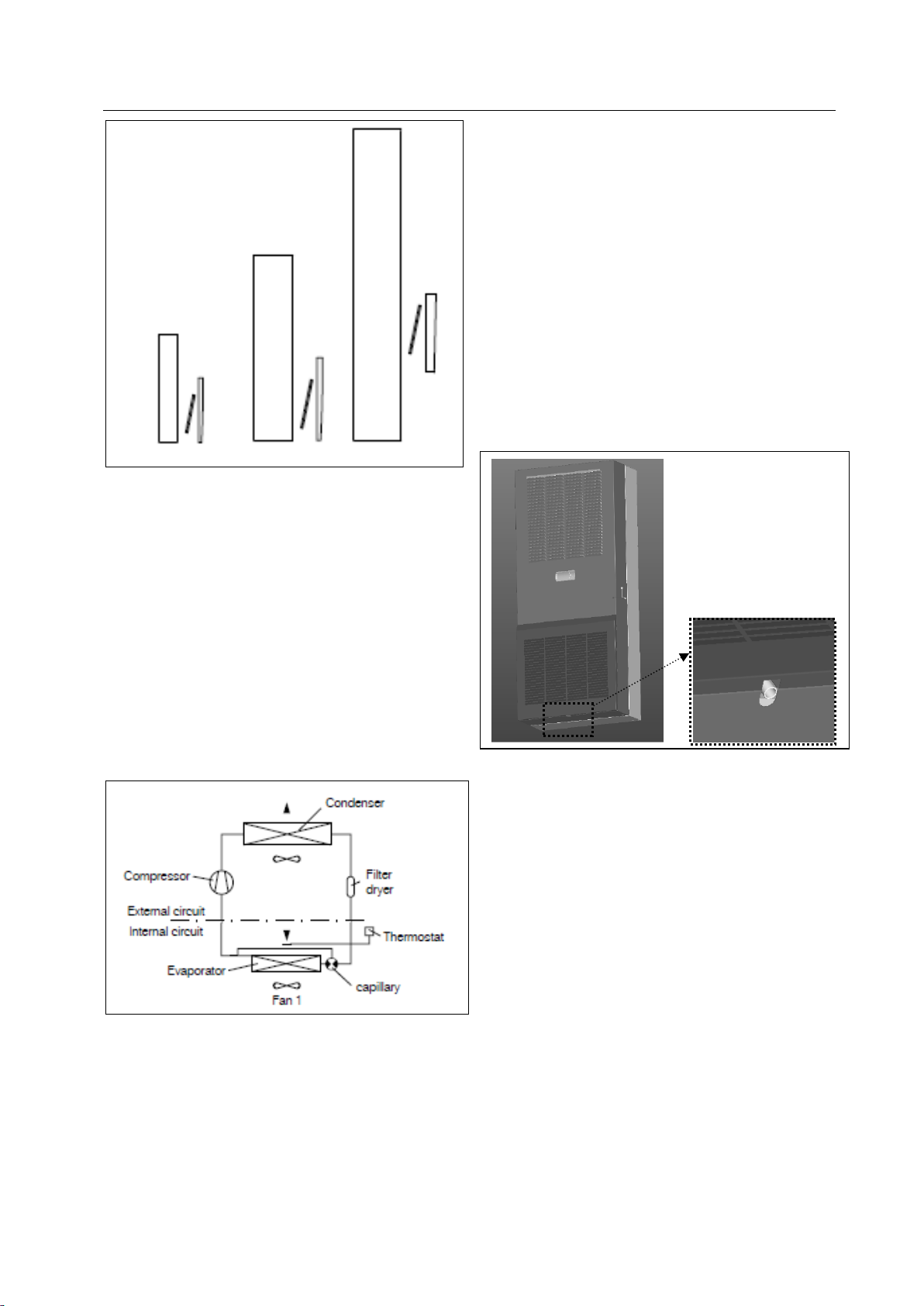
7Technical informations
The cooling unit (compressor refrigeration unit) con-
sists of four main components: the coolant compres-
sor, evaporator, condenser, and the capillary, which
are connected by suitable Pipe-work. This circuit is
filled with a readily boiling substance, the refrigerant.
The R134a (CH2FCF3) refrigerant is free from chlo-
rine. It has an ozone destroying potential (ODP) of 0
and is therefore environmentally friendly. A filter
dryer which is integrated in the hermetically sealed
cooling circuit, provides effective protection against
moisture, acid, dirt particles, and foreign bodies with-
in the cooling circuit.
7.1.1Operation of the cooling unit
Figure 6: Operation of the cooling unit
The compressor takes the gaseous refrigerant from
the evaporator and compresses it to a higher pres-
sure in the condenser. During this process the tem-
perature of the refrigerant rises above the ambient
temperature and heat can be dissipated to the envi-
ronment via the surface of the condenser. Then the
refrigerant is liquefied and, by means of a thermos-
tatically controlled capillary, returned to the evapora-
tor, where it evaporates at low pressure. The heat
required for complete evaporation is drawn from the
enclosure interior causing it to cool down. The cool-
ing cycle is thus completed, the aforementioned
process of the heat transfer starts afresh.
7.1.2Condensate discharge
A drain pipe fitted to the evaporator divider panel
ensures that any condensate which may form on the
evaporator (at high air humidity, low temperatures
inside the enclosure) is drained away from the bot-
tom of the unit. For this purpose, a length of hose
should be fitted to the condensate pipe connection
piece. The condensate must be able to run off freely.
If the condensate is to be drained off over a greater
distance, then care must be taken that the hose is
free from kinks and a check for correct drainage
made.
8Handling instructions
8.1 Fitting the cooling unit
The enclosure cooling unit may optionally be exter-
nally mounted on the enclosure (1) or partially inter-
nally mounted (2).

8 Handling instructions
Page 8 of 13 Rittal cooling unit assembly and operating instructions
Figure 7: Installation method
To this end, cut the side panel or door of the enclo-
sure, as per the Manu included with the supply, and
drill the relevant holes.
Notice!
For mounting the units SK 3370724 in
the TS side panel or rear panel, we
recommend the use of enclosure panel
fasteners TS 8800.071 (see RITTAL
Catalogue).
8.1.1External mounting of the cooling
unit
Cut the supplied sealing tape to the correct
length and stick it carefully along the back of the
unit so that no gaps are left at the joints.
Figure 8: Applying the self-adhesive tape
Screw the supplied grub screws into the blind
nuts on the rear of the unit.
Secure the unit using the supplied washers and
nuts.
Figure 9: Securing the unit (all compact units except 3370220)
8.1.2Partial internal mounting of the
cooling unit (accessories not in-
cluded)
Fix the 4 mounting bars on the air conditioner by
using screws.
Figure 10: Fixing mounting bars
Cut the supplied sealing tape to the correct
length and stick it carefully along the inside of the
rear enclosure half so that no gaps are left at the
connection points.
Figure 11: Sticking sealing tape
Mount the front enclosure tray using the washers
and nuts.
8 Handling instructions
Page 9 of 13 Rittal cooling unit assembly and operating instructions
Figure 12: Mounting cooling units
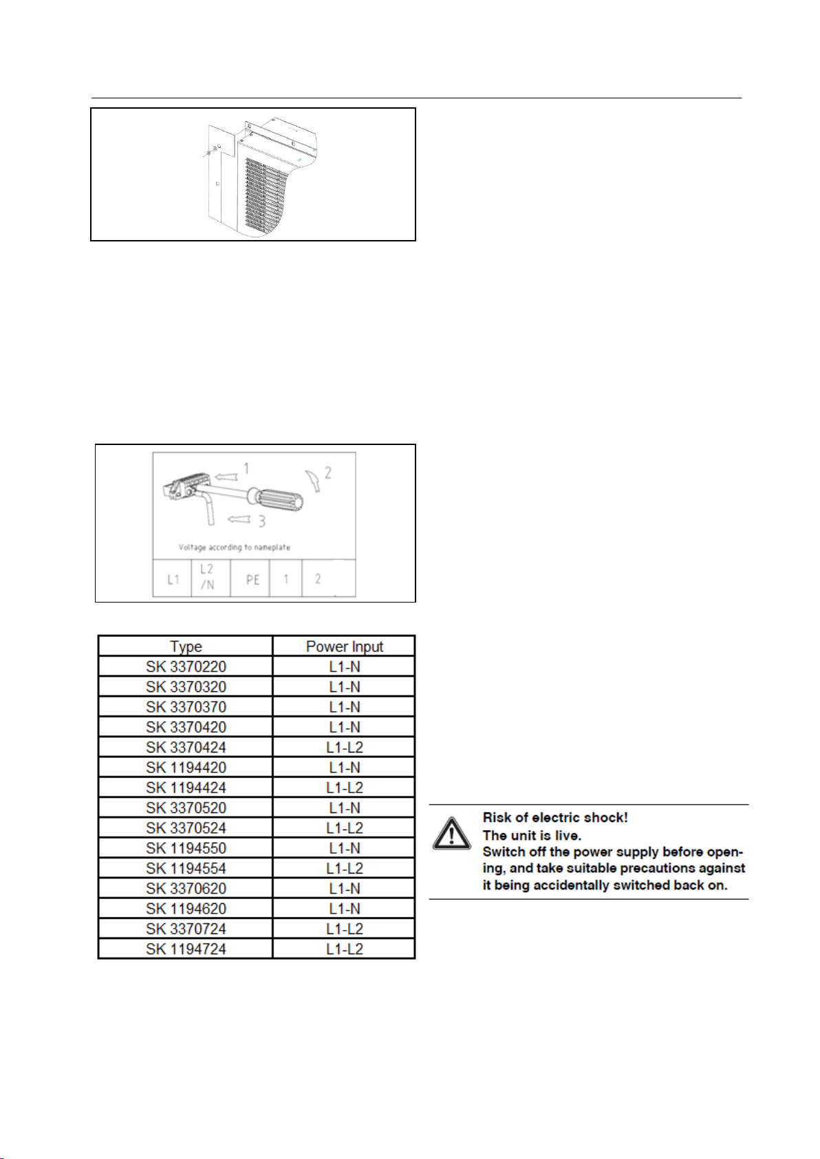
8.2 Electrical connection
When performing electrical installation, shall comply
with national and local institute There are existing
regulations and provisions of the local power supply
bureau. Electrical safety. Installed by qualified elec-
trician, electrician must comply with the current stan-
dards and regulations. Connect the power supply
cable according to the power supply tension as
shown on the name plate by following the instruc-
tions below:
Figure 13: Electrical connection
8.2.1Connection data
The connected voltage and frequency must cor-
respond to the values stated on the rating plate
The cooling unit must be connected to the mains
via an all-pin isolating device, which ensures at
least 3 mm contact opening when switched off
No additional temperature control may be con-
nected upstream of the unit at the supply end
Install the pre-fuse specified on the rating plate to
protect the cable and equipment from short-
circuits
The mains connection must ensure low-noise
8.2.2Overvoltage protection and power
line load
The unit does not have its own overvoltage pro-
tection. Measures must be taken by the operator
at the supply end to ensure effective lightning
and overvoltage protection. The mains voltage
must not exceed a tolerance of ±10%.
In accordance with IEC 61 000-3-11, the unit is
intended solely for use at sites with a continuous
current-carrying capacity (incoming mains power
supply) of more than 100 A per phase and with a
supply voltage of 400/230 V. If necessary, the
electricity supply company must be consulted to
ensure that the continuous current-carrying ca-
pacity at the point of connection to the public grid
is sufficient for connection of such a unit.
The fans and compressors in single- and three-
phase units are intrinsically safe (thermal winding
protection). This also applies to transformer ver-
sions, types 3370.420, 3370.520, 3370.724 and
to special-voltage units which are likewise
equipped with a transformer.
Install the slow pre-fuse specified on the rating
plate (miniature circuit-breaker with appropriate
characteristic or gG
standard type slow fuse, circuit-breaker for plant
or transformer protection) to protect the cable
and equipment from short-circuits. Select a suit-
able circuit-breaker in accordance with the infor-
mation specified on the rating plate: Set it to the
minimum specified value. This will achieve the
best short-circuit protection for cables and
equipment. Example: Specified setting range 6.3
10 A; set to 6.3 A.
9Inspection and maintenance
The cooling circle is designed in the form of a main-
tenance-free, hermetically sealed system. The cool-
ing unit is filled with the required quantity of refrige-
rant at the factory, checked for leaks, and subjected
to a functional test run.
The installed maintenance-free fans are mounted on
ball bearings, protected against moisture and dust.
The life expectancy is at least 30,000 operating
hours. The cooling unit is thus largely maintenance-

9 Inspection and maintenance
Rittal cooling unit assembly and operating instructions page 10 of 13
free. All that may be required from time to time is to
clean the components of the external air circuit using
a vacuum cleaner or compressed air if they become
visibly dirty. Any stubborn, oily stains may be re-
moved using a non-flammable detergent, such as
degreaser. Maintenance interval: 2,000 operating
hours. Depending on the level of contamination in the
ambient air, the maintenance interval may be re-
duced to suit the air pollution intensity.
Notice!
Caution!
Risk of fire!
Never use flammable liquids for
cleaning.
Sequence of maintenance measures:
Check the level of dirt.
Filter soiling? Replace the filter if necessary.
Cooling membranes soiled? Clean if necessary.
Activate test mode; cooling function OK?
Check noise generation of compressor and fans.
Sequence of maintenance measures:
-Check the level of dirt.
-Filter soiling? Replace the filter if necessary.
-Cooling membranes soiled? Clean if necessary..
-Check noise generation of compressor and fans.
9.1 Compressed air cleaning
Figure 14: Break power
Figure 15: Twist off the screw on the top of the cover
Figure 16: Twist off the screw on the bottom of the cover
Figure 17: Open the cover
Figure 18: Disconnect the plug of the display

9 Inspection and maintenance
Page 11 of 13 Rittal cooling unit assembly and operating instructions
Figure 19: Twist off the screw of the outside fan(1)
Figure 20: Twist off the screw of the outside fan(2)
Figure 21: Remove the outside fan
Figure 22: Disconnect the plug of the outside fan(1)
Figure 23: Disconnect the plug of the outside fan(2)
Figure 24: Clean the heat pipe and compressor
chamber using compressed air

9 Inspection and maintenance
Rittal cooling unit assembly and operating instructions page 12 of 13
Figure 25: Clean the heat exchanger using
compressed air
10 Storage and disposal
Store the cooling unit in the appropriate position
for transport.
The closed cooling cycle contains refrigerant and
oil, which must be properly disposed of for the
protection of the environment. Facilities for dis-
posal are available at the Rittal plant.
Please contact us for advice.
11 Scope of supply and guaran-
tee
1 cooling unit, ready for connection
1 sealing tape
1 set of mounting and operating instructions
Guarantee:
This unit is covered by a 1-year guarantee from
the date of supply, subject to correct usage(see
also Safety notices under heading 4.). Within this
period, the returned unit will be repaired in the
factory or replaced free of charge. The cooling
unit is to be used for the cooling of enclosures
only. If it is connected or handled improperly the
manufac
this case we are not liable for any damage
caused.

RITTAL GmbH & Co. KG
Postfach 1662 ·D-35726 Herborn
Phone + 49(0)2772 505-0 ·Fax + 49(0)2772 505-2319
This manual suits for next models
10
Table of contents
Other Rittal Cooling Box manuals


