4
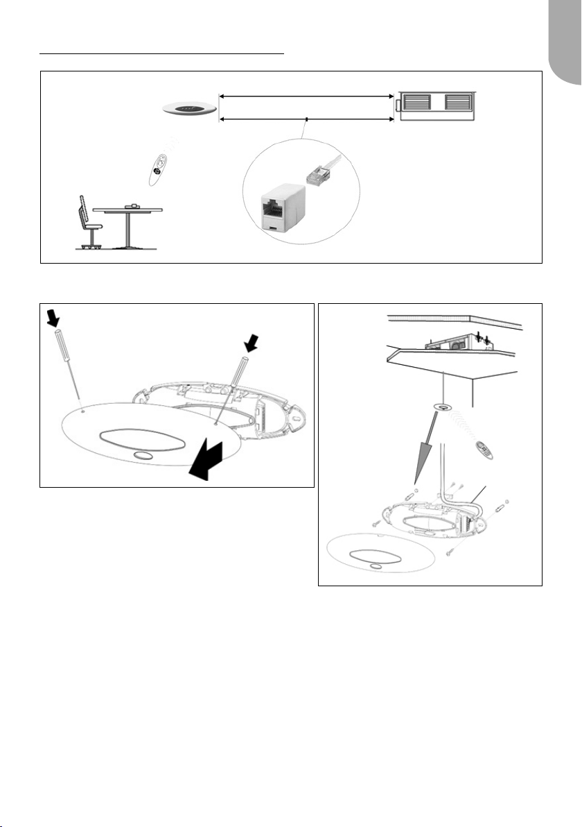
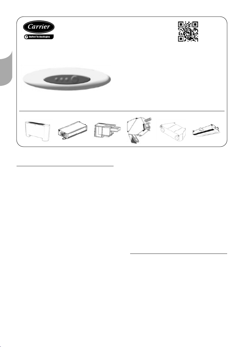
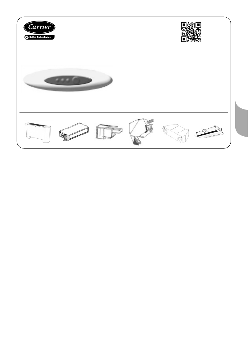
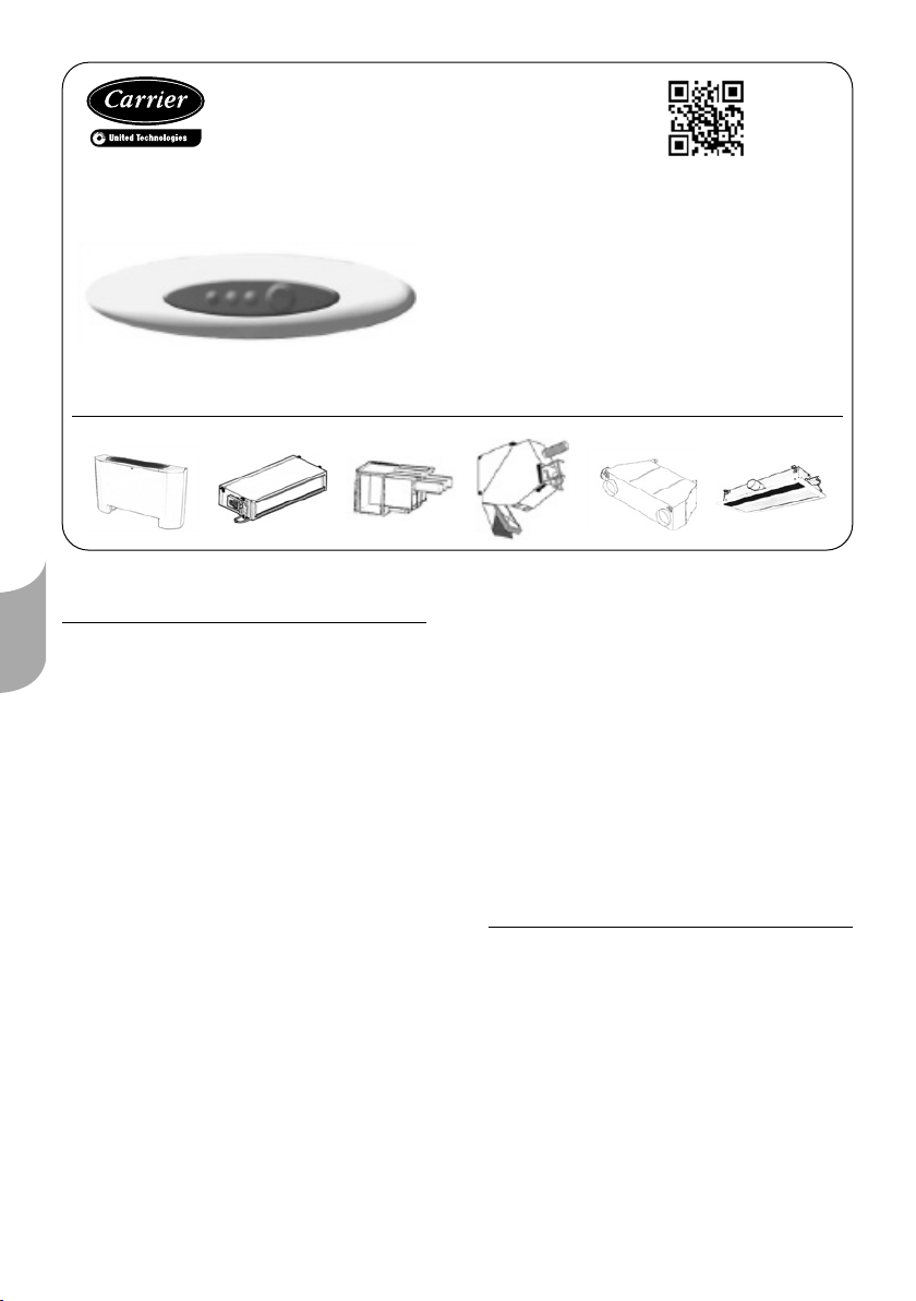
Récepteur à infrarouge
WTC-IS
Manuel d’installation
Contenu de l'emballage
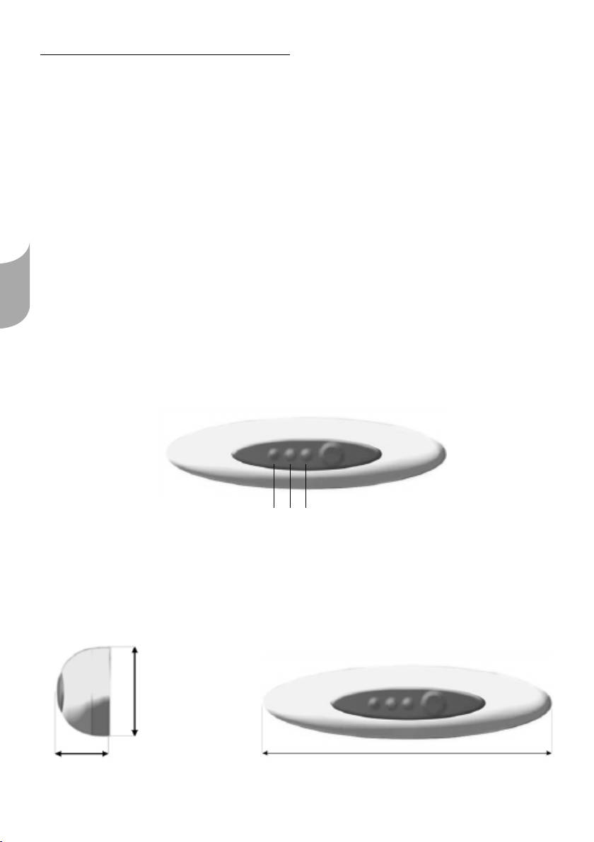
■Récepteur à infrarouge
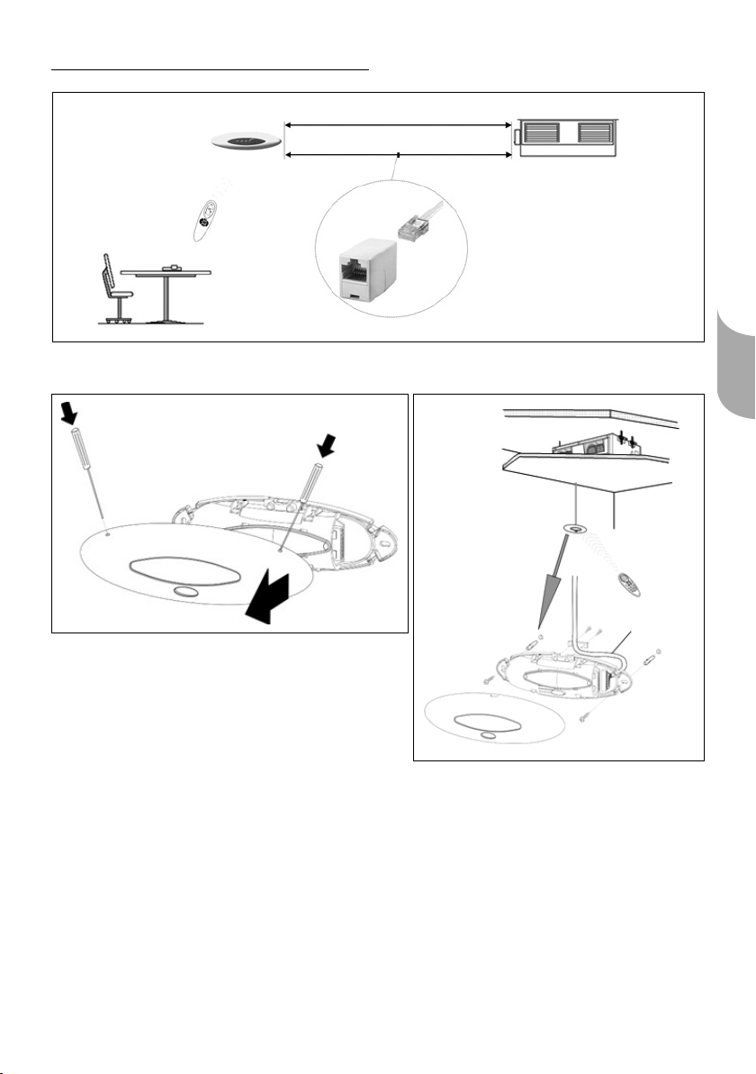
■Câble RJ45 15 m
■Deux vis et deux chevilles en plastique
■Manuel d'installation
Précautions d'installation
Introduction
Lisez attentivement les instructions avant
d'installer ce dispositif. Le fabricant
décline toute responsabilité pour tout
inconvénient ou dommage résultant du
non-respect des instructions fournies dans
le présent manuel.Toute réclamation au
titre de la garantie est nulle si les
instructions fournies dans le présent
manuel ne sont pas respectées.
■Seuls des installateurs d'entretien
qualiésdoiventêtreautorisésà
installer et à entretenir l'équipement.
■Toutes les instructions fournies dans le
présentmanueldoiventêtrelueset
suivies.
■ L'équipemententrantdoitêtre
soigneusementvériéenvuede
détecter d'éventuels dommages
apparus pendant le transport ou
résultant d'une manipulation
incorrecte. En cas de dommage,
déposez une réclamation auprès de
l'entreprise de transport.
Exigences d'installation générales
Éliminez tous les matériaux d'emballage
conformément à toutes les
réglementations locales en vigueur.
Protection contre les électrocutions
Prenezdesprécautionsand'empêcher
les décharges électrostatiques sur
l'appareil lors de l'installation, de
l'entretien ou du fonctionnement de
l'équipement.
Environnement
Température de stockage : -20 à 50°C
Humidité relative : 0 à 95 % sans condensation
Température de fonctionnement : 5 à 40°C
Français