Carrier TSTATCCREC01 User manual

MULTI-STAGE WIRELESS RECIEVER
Installation Instructions
TSTATCCREC01
TSTATBBREC01
P474-1100REC
Wireless Reciever
NOTE: Read the entire instruction manual before starting the installation.
Form: IM-TSTAT-10 Cancels: Printed in U.S.A. Catalog No. 13TS-TA36
HEAT
COOL
FAN
POWER
HEAT
PUMP
HEAT
COOL
&
Page 1
Table Of Contents
PREPARATION
REMOVE OLD THERMOSTAT
MOUNT WALL PLATE & WIRE
CONNECTIONS & SWITCHES
WIRING DIAGRAMS
CALABRATION
TROUBLESHOOTING
CAUTION Follow Installation Instructions carefully.
DISCONNECT POWER TO THE HEATER -
AIR CONDITIONER BEFORE REMOVING
THE OLD THERMOSTAT AND INSTALLING
THE NEW THERMOSTAT. WARNING
2
3
4
5
7
10
11
FCC ID MUH-T10016
This device complies with Part 15 of the FCC rules.
Operation is subject to the following two conditions:
(1) this device may not cause harmful interference,
and (2) this device must accept any interference
received, including interference that may cause
undesired operation.
This receiver is designed to operate @
0-70 C
Proper installation of the receiver will be
accomplished by following these step
by step instructions. If you are unsure
about any of these steps, call a qualified
technician for assistance.
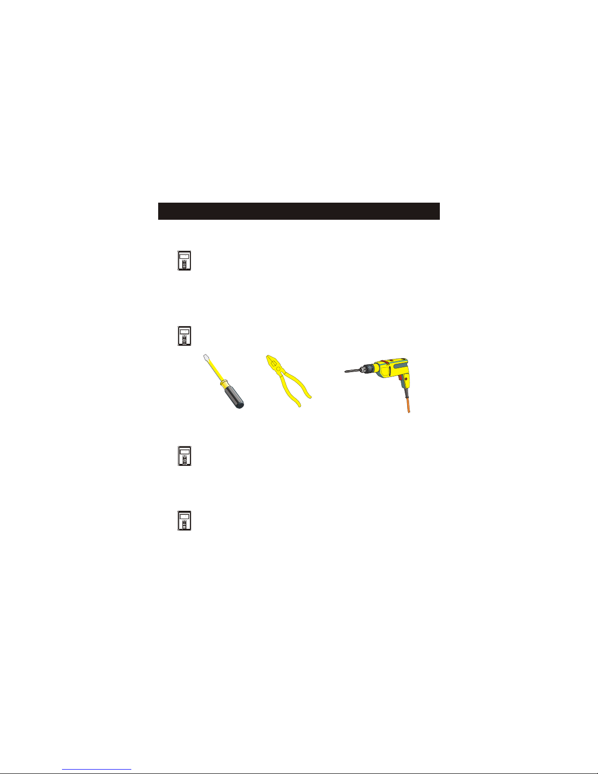
Assemble tools as shown below.
Flat Blade
Screwdriver
Wire cutter
& Stripper
Drill with
3/16 inch
Drill Bit
Make sure your Heater/Air Conditioner
is working properly before beginning
installation of the receiver.
Carefully unpack the receiver.
Save the screws, wall anchors, and
instructions.
STEP #1
PREPARATION
Page 2
70
70
12:00
Set
Cool
FanAuto
MODE
FAN
70
70
12:00
Set
Cool
FanAuto
MODE
FAN
70
70
12:00
Set
Cool
FanAuto
MODE
FAN
70
70
12:00
Set
Cool
FanAuto
MODE
FAN

Turn off the power to the Heating/Air
Conditioning system at the main fuse
panel. Most residential systems have
a separate breaker for disconnecting
power to the furnace.
Remove the cover of the old thermostat.
If it does not come off easily check for
screws.
Loosen the screws holding the thermostat
base or subbase to the wall, and lift away.
Disconnect the wires from the old
thermostat. Tape the ends of the wires
as you disconnect them, and mark them
with the letter of the terminal for easy
reconnecting to the receiver.
STEP #2
REMOVE OLD THERMOSTAT
Page 3
70
70
12:00
Set
Cool
FanAuto
MODE
FAN
70
70
12:00
Set
Cool
FanAuto
MODE
FAN
70
70
12:00
Set
Cool
FanAuto
MODE
FAN
70
70
12:00
Set
Cool
FanAuto
MODE
FAN
70
70
12:00
Set
Cool
FanAuto
MODE
FAN
Keep the old thermostat for reference
purposes, until your new thermostat is
functioning properly.

STEP #3
MOUNT WALL PLATE AND WIRE
Page 4
If the terminal designations on your old
thermostat do not match those on the
new thermostat, refer to the chart below,
or the wiring diagrams that follow.
70
70
12:00
Set
Cool
FanAuto
MODE
FAN
70
70
12:00
Set
Cool
FanAuto
MODE
FAN
* C may not be used on all systems.
** O/B is used if your system is a Heat Pump.
Mount the wall plate with the 2 screws supplied.
Use the supplied wall anchors if mounting on
drywall. A 3/16" hole will have to be drilled for
the wall anchors.
Wire from the
old thermostat
terminal marked Function
Install on the
new receiver
terminal marked
G or F Fan G
Y1, Y or C Cooling Y1
W1, W or H Heating W1,O,B
W1,O,B**
PowerRh, R, M, Vr, A R
C
O/B
C *
Common
Rev. Valve
Y2 Y2
W2 W2
2nd Stage Cool
2nd Stage Heat
RS+5 Remote Sensor +5vdc
RS Remote Sensor Signal
RS G Remote Sensor Ground
CK1
CK2
Dry Contact Switch
Dry Contact Switch

Connections & Switches - Setting House Code
Page 5
W2
Y2
R
W1
O
B
Y1
GC
11
22
44
88
1616
3232
EHEH
HPHP
ONON
OFFOFF
Antenna Terminals for
Connection to
HVAC
Dip
Switches
Circuit Board
Rear Housing
11
22
44
88
1616
3232
EHEH
HPHP
ON
OFF
11
22
44
88
1616
3232
EHEH
HPHP
ON
OFF
Add all ON switches to
arrive at HOUSE CODE
number. All thermostats
communicating with this
receiver must have the
same House Code #.
All # switches off = 0
ON Indicator
Example:
House Code 10,
2+8=10
O / BO / B O / BO / B

Connections & Switches - Heat Pump
Page 6
11
22
44
88
1616
3232
EHEH
HPHP
ONON
OFFOFF
Antenna
Dip
Switches
Circuit Board
Heat Pump
11
22
44
88
1616
3232
EHEH
HPHP
O / BO / B
ON
OFF
To configure the receiver
for heat pump operation
Slide HP switch to the
ON position as shown.
Reversing Valve polarity
(O or B) can also be set.
OFF = O, ON = B
ON Indicator
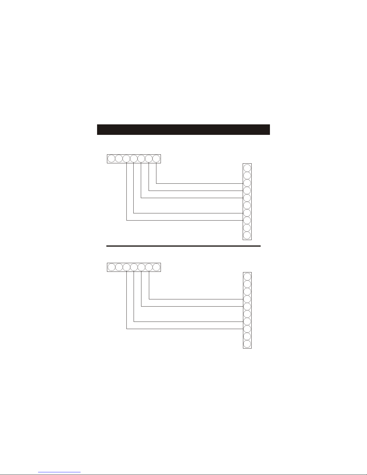
Sample Wiring Diagrams
Receiver
Receiver
Page 7
R
C
G
Y1
Y2
W1
W2
O
E
L
RC
G
Y1
Y2 W1
W2
O
24 vac common
24 vac return
fan relay
compressor relay
1st stage heat circuit
R
C
G
Y1
Y2
W1
W2
O
E
L
RC
G
Y1
Y2 W1
W2
O
24 vac return
fan relay
compressor relay
1st stage heat circuit
5 Wire, 1 Stage Cooling, 1 Stage Gas Heat
4 Wire, 1 Stage Cooling, 1 Stage Gas Heat
Residential Gas or Electric Heat *,
Electric Cool, split systems & package
units
Residential Gas or Electric Heat *,
Electric Cool, split systems & package
units
*If using electric heat this option must be
selected on during advanced setup.
*If using electric heat this option must be
selected on during advanced setup.

Sample Wiring Diagrams
Page 8
R
C
G
Y1
Y2
W1
W2
O
E
L
RC
G
Y1
Y2 W1
W2
O
24 vac common
24 vac return
fan relay
compressor relay
2nd stage compressor relay
1st stage heat circuit
R
C
G
Y1
Y2
W1
W2
O
E
L
RC
G
Y1
Y2 W1
W2
O
24 vac common
24 vac return
fan relay
compressor relay
1st stage heat circuit
2nd stage heat circuit
Residential 2 Stage Cooling, with
Gas or Electric Heat*
Residential & commercial 1 Stage Cooling,
with 2 Stage Gas or Electric Heat*
6 Wire, 2 Stage Cooling, 1 Stage Heat
6 Wire, 1 Stage Cooling, 2 Stage Heat
Receiver
Receiver
* If using electric heat, this option must
be selected during advanced setup.

Sample Wiring Diagrams
Page 9
R
C
G
Y1
Y2
W1
W2
O
E
L
RC
G
Y1
Y2 W1
W2
O
24 vac common
24 vac return
fan relay
compressor relay
2nd stage compressor relay
1st stage heat circuit
2nd stage heat circuit
R
C
G
Y1
Y2
W1
W2
O
E
L
RC
G
Y1
Y2 W1
W2
O
24 vac common
24 vac return
fan relay
compressor relay
reversing valve
Commercial Gas or Electric Heat ***,
Electric Cool, split systems & package units
including Commercial Heat Pumps **
No auxiliary heat, residential Heat Pumps ,
split systems & package units
7 Wire, 2 Stage Cooling, 2 Stage Heat
5 Wire, 1 Stage Cooling, 1 Stage Heat - Heat Pump*
Receiver
Receiver
* If using residential heat pump, this option
must be selected on during advanced setup.
** Commercial heat pumps do not have
the heat pump turned on in advanced setup.
*** If using electric heat, this option must
be selected on during advanced setup.
Other manuals for TSTATCCREC01
1
This manual suits for next models
2
Table of contents
Other Carrier Receiver manuals


