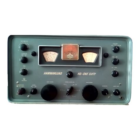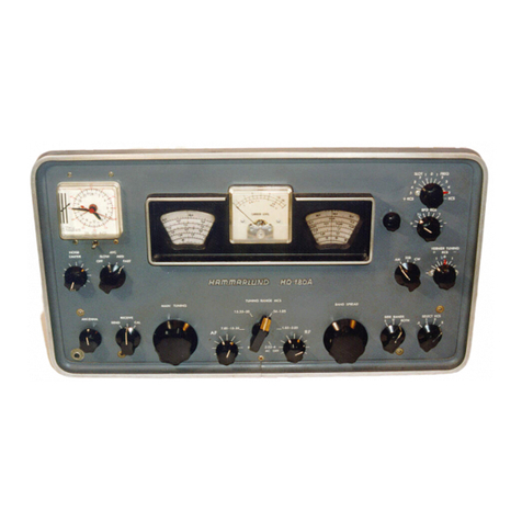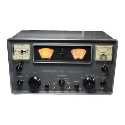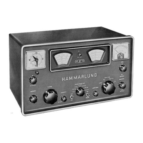
Tuning
Lock-The
tuning lock, located to
the
right
of
the
tuning knob, provides apositive locking
for
the
tuning mechanism without affecting
the
fre·
quency setting, when
it
is desired
to
prevent accidental
shifting
of
the
tunin~·or
when
the
receiver is operated
under asevere condition of vibration.
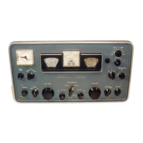
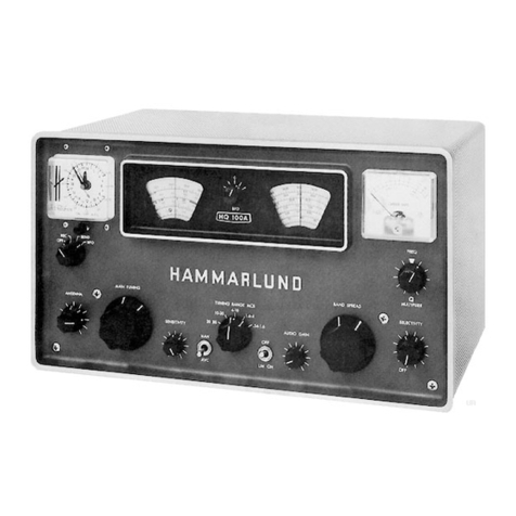
Tuning
Meter-
The
tuning meter
at
the
upper
left on
the
front panel is useful
in
accurately tuning a
signal and provides an indication of the relative
strength
of
the received
si~nal
in db from 1microvolt.
The
"METER
AD]
RP" control at the rear
of
the
chassis provides adjustment
of
the
plus 20 db reading
on
the
RF
scale, with a10 microvolt input signal. De-
pression
of
the
"METER
SWITCH"
converts
the
meter circuit for indication of
the
AF
output power
level
in db
from
6miljiwilttll.
Thill
IIwitch is Ilpnng
returned
to
the RF scale circuit position when released
and should not be
depTe8lied
for
the
AF
scale unless
the audio
output
bas been adjusted for low power out-
put, by means
of
headphones
or
speaker. Failure
to
abserve
this precaution
fUy
re.<"\1lt
in
damage
to
the
meter.
The
"METER
AD]
AF"
control at
the
rear of
the chassis provides adjustment
of
the
0db reading on
the
AF
scale, which should
be
made when
the
AF
out-
put
power from
the
600 ohm audio output terminals is
6milliwatts or 1.9 volts across a600 ohm load.
Band Change-
The
large knob,
to
the
left, is
the
band change controL Each revolution of this control
turns
the
turret, containing
the
RF
and
HF
oscilla.tor
coil, trimmer and switch contact assemblies, from one
frequency band to
the
next.
The
turret has no stops
and may be turned in either direction desired. A
posi-
tive detent machanism assures correct location
of
the
\'anous bands.
The
band change control simulta.ne-
ously operates
the
small frequency
ba.nd
dial, loca.ted
at tht:: ct:nter uf
the
panel
anJ
.uign" the Jial frequency
indicator
with
the
proper
f\C3.le.
SelectivitySwitch -
The
selectivity switch provides
three crystal and
three
non-crystal degrees
of
selec-
tivity, ranging from extremely sharp, for C'W recep-
tion,
to
broad for good fidelity Mewoperation.
The
control knob dial indicates
the
6db band width
at
each
setting.
Phasing Control -
The
phasing control permits
high attenuation
of
closely adjacent channel interfer'
ence on either side
of
the signal frequency, when
the
crystal selectivity positions are used.
Beat Frequency Oscillator -
The
beat frequency
o.scillator is turned
"on"
for C'W signal operation by
the
"MOD-CW"
switch.
The
beat frequency dial
should be set at
xero
for tuning-
to
.u:ro
beat and then
adjusted to
~ve
the
desired audio pitch.
The
beat fre-
quency oscillator injection voltage is adjustable
by
the
"BFO
INj"
control on
the
rear skirt
of
the
chassis.
Noise Limiter-
The
noise limiter switch is inde-
pendent
of
other controls and
is
useful
in
gready at-
tenuating
noLse
interference from ignition
or
similar
pulse type sources, regardless
of
the
mode
of
opera-
tion.
Send-Receive-
The
send-receive switch permits
desensitizing the receiver during transmission periods,
to prevent damage to
the
receiver, when operated in
proximity
to
the
transmitter and provides instant
re_
turn
to reception between transmission periods.
Rday
Receptacle -
The
relay receptacle, on the
rear
of
the
receiver, is connected in parallel with the
send-receive switch and provides for the connectiorr of
an
externally connected relay, to perform
the
send-
receive operation.
When
the relay
is
used
the
send-
receive switch
is
left in
the
"open" or "send" position.
AVC-Manual Switch
~
The AVC-Manual Switch
permits the choice
of
either
AVC
or
Ma.nual sensitiv-
ity operation
as
desired.
The
A
VC
has adelay bias,
which insures maximum sensitivity for weak "ignab.
RF
Gain
Control-
The
RF
gain control provides
adjustment
of
the
sensitivity for signals
of
various
strength,
when
under
the
"manual" operating condi-
tion, in order that
the
receiver sensitivity may be ad-
justed
to
suit
the signal strength and prevent overload-
ing.
This
control is also in the circuit when operating
on
AVe,
in
order
that
the
sensitivity may be adjusted
to reduce undesirable noise during "ojf" periods in the
transmission
of
the
received signal.
\Vhen
it
is
de-
sired
to
use
the
tuning- meter for indication
of
relative
signal strength,
the
RF gain control should be
at
maxi-
mum.
Audio Gain
Control-
The
audio gain control ad-
Justs
the
audio
input
to the audio amplifier tube.
It
should be adjusted for the required audio
output
when
operating on
AVC
and is best left
at
or
near maximum
when operating on
MANUAL
control.
Phono
Input-Terminals
are provided on
the
rear
df
the
receiver for phonograph
or
other
audio fre-
quency source input to
the
audio frequency amplifier.
Convenience
Ouder
- A power outlet receptacle is
provided on the rear of
the
receiver chassis for operat-
ing an accessory, such
as
an electric clock
or
lamp.
V
MAINTENANCE
This
receiver
is
designed for continuous duty and
should normally require little attention beyond
the
replacement
of
tubes. However,
lShould
trouble de-
velop
that
cannot be eliminated with new tubes,
the
socket voltages and resistances should be measured
to
chassis.
Any
a.ppreciable departure from
the
values
shown in tables Iand
:2
will genenlly indicate the
"
component
or
circuit at fault.
Operating- and maintenance
of
the receiver will
be
greatly facilitated if
the
contents of this instruction
manual are thoroughly digested. Approximate input
signal values for stage by stage gain checks are shown
in table
4.
