RICEVITORE A INFRAROSSI
1. Istruzioni preliminari
2. Versione
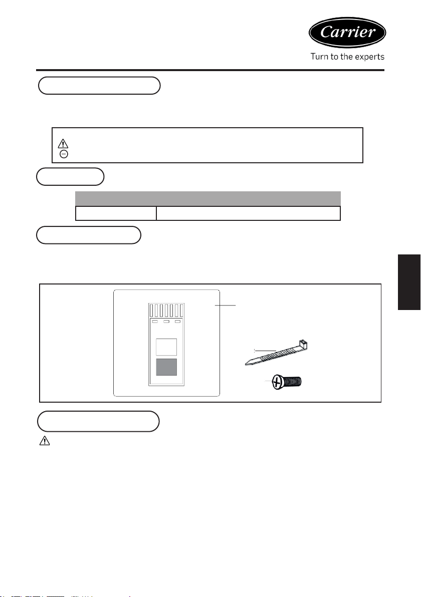
3. Contenuti del kit
4. Istruzioni preliminari
Il presente libretto di istruzioni è parte integrante del manuale del dispositivo su cui è installato il kit. Nel
manuale fornito, fare riferimento alle sezioni AVVERTENZE e NORME DI SICUREZZA DI BASE.
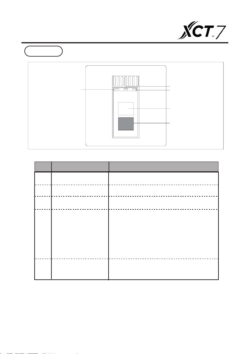
1 Ricevitore a infrarossi
2 Cinghia
3 Vite
20064592 Ricevitore a infrarossi
In questa pubblicazione vengono utilizzati i seguenti simboli:
AVVERTENZA = azioni che richiedono un’attenzione particolare e una formazione adeguata.
VIETATO = azioni che NON DEVONO essere eseguite IN NESSUN CASO.
Codici
1
1
2
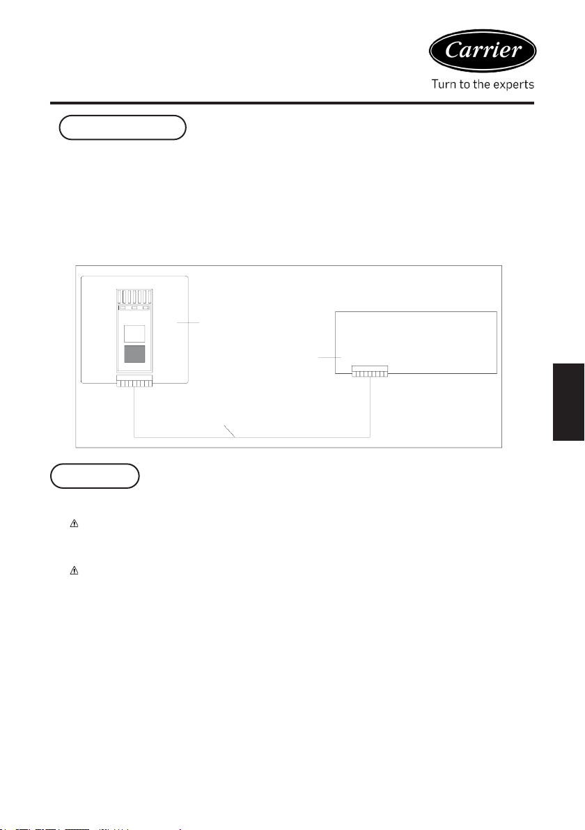
Per una corretta installazione, tenere presente che il pannello:
o Deve essere installato su una parete, preferibilmente non sulla parete perimetrale e su quella priva di
tubazio ni calde o fredde al suo interno.
o In caso di installazione a parete, il dispositivo deve essere montato a 1,5 m dal pavimento.
o Non deve essere posizionato accanto a porte, nestre, dispositivi di cottura, radiatori e ventilconvettori. In
generale, non deve essere posizionato in condizioni che potrebbero alterare la temperatura misurata.
o È necessario prendere in considerazione la lunghezza massima del cavo di collegamento.
o Utilizzare un cavo schermato per il collegamento.
o Il cavo di collegamento non deve essere impiombato; se è necessario impiombarlo, deve essere stagnato
e adeguatamente protetto.
o Qualsiasi interramento del cavo di collegamento deve essere separato dai li sotto tensione.
1
Italiano
COMP OPERTIMER
3
2
1