manuals.online logo
Brands
  1. Home
  2. •
  3. Brands
  4. •
  5. Carrier
  6. •
  7. Thermostat
  8. •
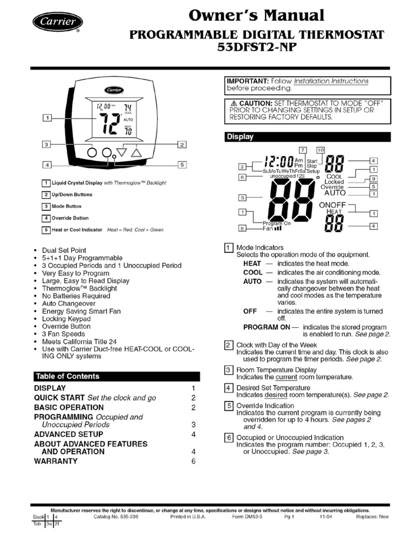
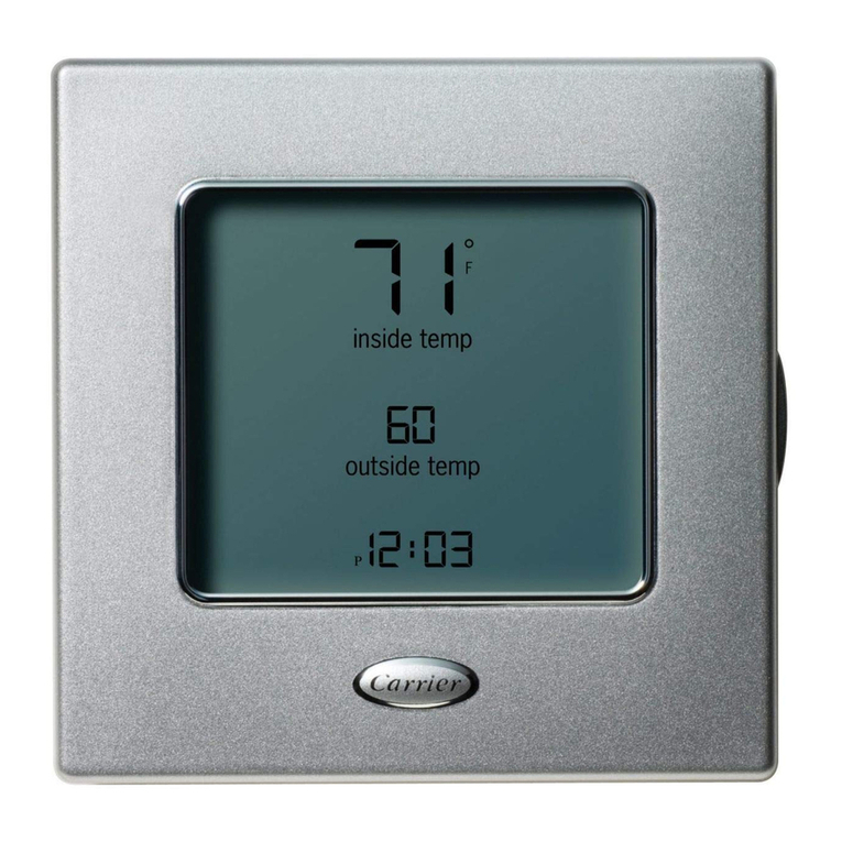
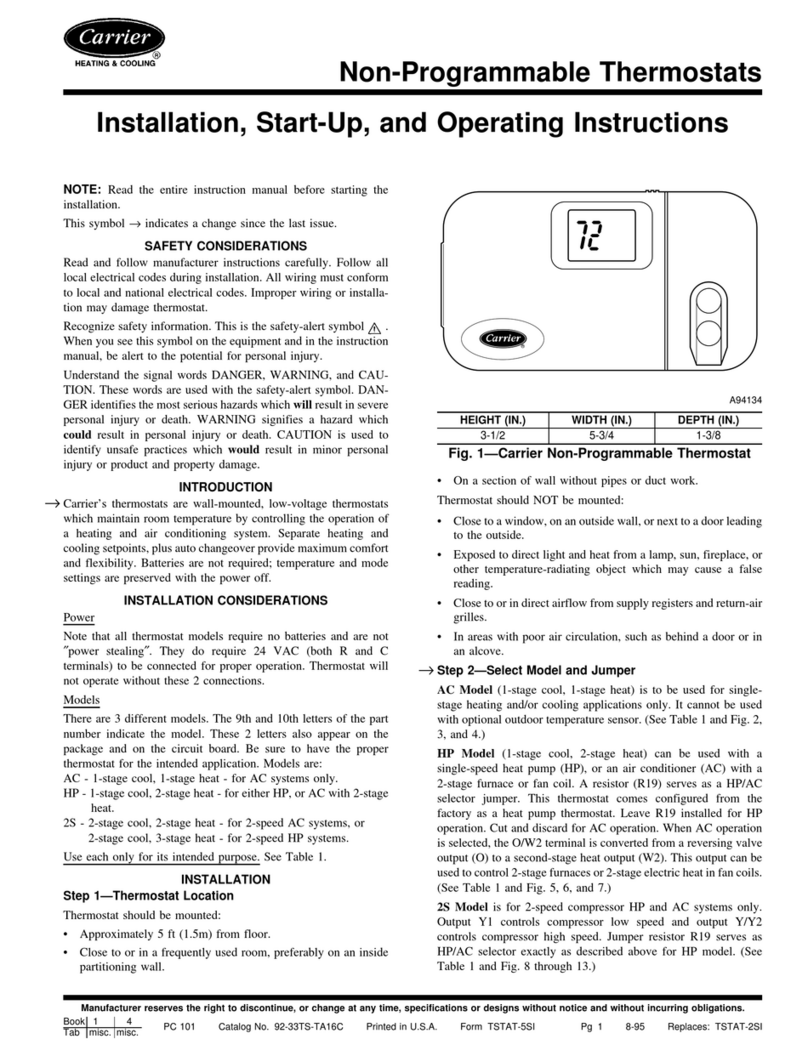
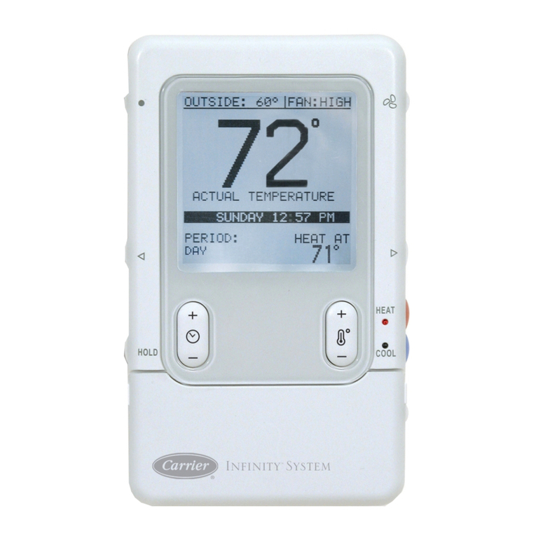
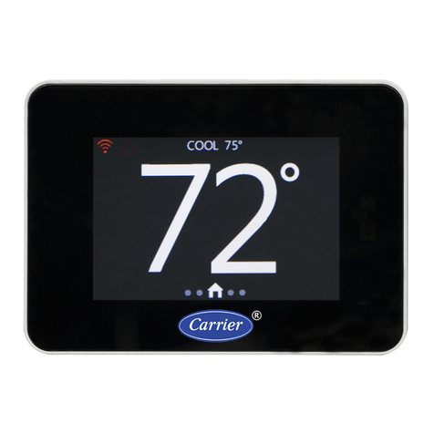
  9. Carrier CONNECT 33CONNECTSTAT User manual

Carrier CONNECT 33CONNECTSTAT User manual

FREE CONNECT APP AVAILABLE
at www.carrier.com/connectstat
Wi-Fi®is a registered trademark of Wi-Fi Alliance® Corporation.
Android is a registered trademark of Google Inc. / Apple is a registered
trademark of Apple Corporation
WIRING DIAGRAMS WIRING DIAGRAMS
997-015110-3-R 11-808-575-01
Quick Start Guide
Carrier®Connect™Wi-Fi®
Commercial Thermostat
WHAT’S IN THE BOX
COMPATIBILITY CHECK
This Wi-Fi®thermostat is designed to work with 24V AC
systems requiring both R & C wires. This includes gas,
electric, oil, forced air, variable speed, heat pump and
radiant heat. It can be configured for:
› Heating: 1-4 stages (Y1, Y2, W1, W2)
› Cooling: 1-3 stages (Y1, Y2, *)
› Dehumidification: cooling only 1-3 stages (Y1, Y2, *)
or Carrier’s Humidi-MiZer™ adaptive dehumidification
system 1-2 stages (Y1, Y2, *)
› Heat pump: with auxiliary & emergency heat
(Y1, Y2, W1, W2, *)
› Fan Single Speed (G)
› Power (R, C)
› Dual fuel systems (heat pump with furnace)
› Outdoor Air Temperature (OAT) or Remote Sensor
(optional)
Quick Start
Guide
Security ScrewAnchors
and Screws
Thermostat Wall PlateThermostat Base
Remote Sensor
Pigtail
2-Stage Heat 2-Stage Cool
THERMOSTAT
*
W2
Y1
Y2
W1
G
R
C
Y1
G
R
C
Single Stage Air Handler
INDOOR
Y1
C
RR
C
G
W1
Y1
2-Stage Air Handler
INDOOR
Y1
Y2
G
C
RR
C
G
W1
W2
Y1
Y2
Single Stage HP
OUTDOOR
Y1
W1
G
R
C
1-Stage Heat 3-Stage Cool
THERMOSTAT
*
W2
Y1
Y2
W1
G
R
C
Y1
Y2
G
R
C
Y3
1-Stage Heat 2-Stage Cool
THERMOSTAT
*
W2
Y1
Y2
W1
G
R
C
Single Stage Air Handler
INDOOR
Y1
C
RR
C
G
W1
Y1
2-Stage Heat 2-Stage Cool
THERMOSTAT
*
W2
Y1
Y2
W1
G
R
C
Single Stage AC
OUTDOOR
Y1
Y2
G
R
C
2-Stage HP
OUTDOOR
Y1
Y2
W1
G
R
C
1-Stage Heat 1-Stage Cool
THERMOSTAT
*
W2
Y1
Y2
W1
G
R
C
2-Stage AC
OUTDOOR
1-Stage Heat 1-Stage Cool1
THERMOSTAT
*
W2
Y1
Y2
W1
G
R
C
2-Stage AC
OUTDOOR
Single Stage Air Handler
INDOOR
Y1
G
C
RR
C
G
W1
Y1
W1
W1 W1
W1
1-Stage Heat 2-Stage Cool
THERMOSTAT
*
W2
Y1
Y2
W1
G
R
C
1-Stage Heat 1-Stage Cool
THERMOSTAT
*
W2
Y1
Y2
W1
G
R
C
2-Stage Heat 2-Stage Cool
THERMOSTAT
*
W2
Y1
Y2
W1
G
R
C
Y1
Y2
G
R
C
Single Stage Air Handler
INDOOR
Y1
G
C
RR
C
G
W1
Y1
W1
24VAC
outputs
24VAC
outputs
24VAC
outputs
24VAC
outputs
24VAC
outputs
24VAC
outputs
24VAC
outputs
24VAC
outputs
24VAC
outputs
W1
W1
W2
AC or HP
AC or HP
AC or HP
AC or HP
1-Stage Heat2-Stage Cool
THERMOSTAT
*
W2
Y1
Y2
W1
G
R
C
Y1
Y2
G
R
C
24VAC
outputs
AC with Humidi-MiZer®
Pink & Black Wire Only
(Tape off Pink Wire)
W2
W2
W2 W2
Y2Y2 Y2Y2
Y1
Y2
W1
G
R
C
W2
Y1
Y2
W1
G
R
C
W2
Y1
Y2
W1
G
R
C
W2
W1
Y1
G
R
C
1-Stage Heat 1-Stage Cool
1-Stage Aux heat
THERMOSTAT
*
W2
Y1
Y2
W1
G
R
C
WATER SOURCE OR NON-CARRIER HEAT PUMP
AIR HANDLER OR DX FAN COIL / AC SPLIT SYSTEMAIR HANDLER OR DX FAN COIL / HEATPUMP SYSTEMPACKAGED ROOFTOP
24VAC
outputs
WSHP
O
Y1
G
R
C
2-Stage Heat 2-Stage Cool
2-Stage Aux heat
THERMOSTAT
*
W2
Y1
Y2
W1
G
R
C
24VAC
outputs
WSHP
O
AUX HEAT
W1
AUX HEAT
W1
Y2
W2
2-Stage Heat 2-Stage Cool
THERMOSTAT
*
W2
Y1
Y2
W1
G
R
C
Y1
G
R
C
Single Stage Air Handler
INDOOR
Y1
C
RR
C
G
W1
Y1
2-Stage Air Handler
INDOOR
Y1
Y2
G
C
RR
C
G
W1
W2
Y1
Y2
Single Stage HP
OUTDOOR
Y1
W1
G
R
C
1-Stage Heat 3-Stage Cool
THERMOSTAT
*
W2
Y1
Y2
W1
G
R
C
Y1
Y2
G
R
C
Y3
1-Stage Heat 2-Stage Cool
THERMOSTAT
*
W2
Y1
Y2
W1
G
R
C
Single Stage Air Handler
INDOOR
Y1
C
RR
C
G
W1
Y1
2-Stage Heat 2-Stage Cool
THERMOSTAT
*
W2
Y1
Y2
W1
G
R
C
Single Stage AC
OUTDOOR
Y1
Y2
G
R
C
2-Stage HP
OUTDOOR
Y1
Y2
W1
G
R
C
1-Stage Heat 1-Stage Cool
THERMOSTAT
*
W2
Y1
Y2
W1
G
R
C
2-Stage AC
OUTDOOR
1-Stage Heat 1-Stage Cool1
THERMOSTAT
*
W2
Y1
Y2
W1
G
R
C
2-Stage AC
OUTDOOR
Single Stage Air Handler
INDOOR
Y1
G
C
RR
C
G
W1
Y1
W1
W1 W1
W1
1-Stage Heat 2-Stage Cool
THERMOSTAT
*
W2
Y1
Y2
W1
G
R
C
1-Stage Heat 1-Stage Cool
THERMOSTAT
*
W2
Y1
Y2
W1
G
R
C
2-Stage Heat 2-Stage Cool
THERMOSTAT
*
W2
Y1
Y2
W1
G
R
C
Y1
Y2
G
R
C
Single Stage Air Handler
INDOOR
Y1
G
C
RR
C
G
W1
Y1
W1
24VAC
outputs
24VAC
outputs
24VAC
outputs
24VAC
outputs
24VAC
outputs
24VAC
outputs
24VAC
outputs
24VAC
outputs
24VAC
outputs
W1
W1
W2
AC or HP
AC or HP
AC or HP
AC or HP
1-Stage Heat2-Stage Cool
THERMOSTAT
*
W2
Y1
Y2
W1
G
R
C
Y1
Y2
G
R
C
24VAC
outputs
AC with Humidi-MiZer®
Pink & Black Wire Only
(Tape off Pink Wire)
W2
W2
W2 W2
Y2Y2
Y2Y2
Y1
Y2
W1
G
R
C
W2
Y1
Y2
W1
G
R
C
W2
Y1
Y2
W1
G
R
C
W2
W1
Y1
G
R
C
1-Stage Heat 1-Stage Cool
1-Stage Aux heat
THERMOSTAT
*
W2
Y1
Y2
W1
G
R
C
WATER SOURCE OR NON-CARRIER HEAT PUMP
AIR HANDLER OR DX FAN COIL / AC SPLIT SYSTEMAIR HANDLER OR DX FAN COIL / HEATPUMP SYSTEMPACKAGED ROOFTOP
24VAC
outputs
WSHP
O
Y1
G
R
C
2-Stage Heat 2-Stage Cool
2-Stage Aux heat
THERMOSTAT
*
W2
Y1
Y2
W1
G
R
C
24VAC
outputs
WSHP
O
AUX HEAT
W1
AUX HEAT
W1
Y2
W2
1. TURN POWER OFF
Turn off 24 VAC power at the equipment circuit breaker
or at the system switch. Confirm that power is OFF.
2. INSTALL THERMOSTAT
Position the thermostat base against your wall, and
determine if the accessory wall plate is desired to cover
horizontal 2 x 4 electrical box if installed., if so install
accessory wall plate. Position the thermostat base
against your wall (or wall plate if used) and determine if
the new screw locations align with prior locations. If base
does not align with existing anchor holes, mark new screw
locations with a pencil.
Drywall: Drill 3/16” hole for the anchor
Plaster: Drill 7/32” hole for the anchor
Pull wires through opening in base and secure base
to the wall using provided screws.
Comfort Control for Your Building
Part #: 33CONNECTSTAT
7. SYSTEM CONFIGURATION
Navigate to the “Mode Screen”, ensure that the Mode
is set to Off. Go to the “Fan Screen” and press and hold
the Fan Button for 5 seconds. Once this sequence is
completed, the “System Settings Screen” screen will be
displayed allowing configuration & setup of the system.
The yellow Row Indicator at the right side of the screen
indicates the current location in the list of advanced
settings options. Swipe up or down to navigate through
the settings options. Tap desired field to enter that settings
screen.
8. SETTINGS SCREEN
Navigate from the “Home Screen” to the “Settings
Screen”. This screen allows access to change / view
options in the thermostat. The yellow Row Indicator scrolls
up & down through additional rows of settings. When one
of the displayed icons is pressed, the appropriate screen
will appear.
9. USER APP
The ConnectTM App* is available for Apple IOS®at App
Store®or at Google Play®for Android devices. Search for
“Carrier Connect Thermostat”.
Additional installation & operating instructions
are available by scanning the QR code shown.
*Note: Downloading the App provides enhanced access to your
device. 7 day programming is only available on your mobile
device. Device compatibility requires: Apple IOS 7.0 or later or
Android 4.2 or later.
Select USER SETUP and Register New Account
Make sure email used during registration process is
accessible on your mobile device to receive confirma-
tion email to complete registration process. Select SETUP
NEW THERMOSTAT and follow on screen instructions in the
Connect App to setup new thermostat.
After thermostat is registered successfully SERVICE INFO
screen is displayed where servicing contractor info can
be entered.
Select thermostat from list. The name of thermostat is
listed under DSN (Data Source Name).
The Home screen will now be displayed
10. WEB PORTAL
To access the Connect™ stat with any device
connected to the WEB visit
connectstat.carrier.com and create an account.
3. CONNECT THE WIRES
Straighten the wires out and match your wire configura-
tion to the terminals of the base. One by one, connect
each wire by pushing down on the color coded quick
connect tab and inserting the wire into the connector
opening; release tab to complete.
5. ATTACH THERMOSTAT FACE
Align the thermostat face using hinge
guide on top. Rotate the thermostat down until
tab aligns with hole in base. Install security screw
if required.
6. RETURN POWER TO SYSTEM
The thermostat will display the Home Screen
as shown below:
From the Home Screen, swipe left or right to navigate
through screens. A “right swipe” or “left swipe” motion on
any of the System Settings “sub-screens” will return to the
“System Settings Screen”. You may also press the home
button to return to the Home Screen at any time.
Banner
Wi-Fi®Signal
System Status
Space
Temperature
Page Indicator
2-Stage Heat 2-Stage Cool
THERMOSTAT
*
W2
Y1
Y2
W1
G
R
C
Y1
G
R
C
Single Stage Air Handler
INDOOR
Y1
C
RR
C
G
W1
Y1
2-Stage Air Handler
INDOOR
Y1
Y2
G
C
RR
C
G
W1
W2
Y1
Y2
Single Stage HP
OUTDOOR
Y1
W1
G
R
C
1-Stage Heat 3-Stage Cool
THERMOSTAT
*
W2
Y1
Y2
W1
G
R
C
Y1
Y2
G
R
C
Y3
1-Stage Heat 2-Stage Cool
THERMOSTAT
*
W2
Y1
Y2
W1
G
R
C
Single Stage Air Handler
INDOOR
Y1
C
RR
C
G
W1
Y1
2-Stage Heat 2-Stage Cool
THERMOSTAT
*
W2
Y1
Y2
W1
G
R
C
Single Stage AC
OUTDOOR
Y1
Y2
G
R
C
2-Stage HP
OUTDOOR
Y1
Y2
W1
G
R
C
1-Stage Heat 1-Stage Cool
THERMOSTAT
*
W2
Y1
Y2
W1
G
R
C
2-Stage AC
OUTDOOR
1-Stage Heat 1-Stage Cool1
THERMOSTAT
*
W2
Y1
Y2
W1
G
R
C
2-Stage AC
OUTDOOR
Single Stage Air Handler
INDOOR
Y1
G
C
RR
C
G
W1
Y1
W1
W1 W1
W1
1-Stage Heat 2-Stage Cool
THERMOSTAT
*
W2
Y1
Y2
W1
G
R
C
1-Stage Heat 1-Stage Cool
THERMOSTAT
*
W2
Y1
Y2
W1
G
R
C
2-Stage Heat 2-Stage Cool
THERMOSTAT
*
W2
Y1
Y2
W1
G
R
C
Y1
Y2
G
R
C
Single Stage Air Handler
INDOOR
Y1
G
C
RR
C
G
W1
Y1
W1
24VAC
outputs
24VAC
outputs
24VAC
outputs
24VAC
outputs
24VAC
outputs
24VAC
outputs
24VAC
outputs
24VAC
outputs
24VAC
outputs
W1
W1
W2
AC or HP
AC or HP
AC or HP
AC or HP
1-Stage Heat2-Stage Cool
THERMOSTAT
*
W2
Y1
Y2
W1
G
R
C
Y1
Y2
G
R
C
24VAC
outputs
AC with Humidi-MiZer®
Pink & Black Wire Only
(Tape off Pink Wire)
W2
W2
W2 W2
Y2Y2
Y2Y2
Y1
Y2
W1
G
R
C
W2
Y1
Y2
W1
G
R
C
W2
Y1
Y2
W1
G
R
C
W2
W1
Y1
G
R
C
1-Stage Heat 1-Stage Cool
1-Stage Aux heat
THERMOSTAT
*
W2
Y1
Y2
W1
G
R
C
WATER SOURCE OR NON-CARRIER HEAT PUMP
AIR HANDLER OR DX FAN COIL / AC SPLIT SYSTEMAIR HANDLER OR DX FAN COIL / HEATPUMP SYSTEMPACKAGED ROOFTOP
24VAC
outputs
WSHP
O
Y1
G
R
C
2-Stage Heat 2-Stage Cool
2-Stage Aux heat
THERMOSTAT
*
W2
Y1
Y2
W1
G
R
C
24VAC
outputs
WSHP
O
AUX HEAT
W1
AUX HEAT
W1
Y2
W2
WIRING DIAGRAMS
PACKAGE ROOFTOP
2-Stage Heat 2-Stage Cool
THERMOSTAT
*
W2
Y1
Y2
W1
G
R
C
Y1
G
R
C
Single Stage Air Handler
INDOOR
Y1
C
RR
C
G
W1
Y1
2-Stage Air Handler
INDOOR
Y1
Y2
G
C
RR
C
G
W1
W2
Y1
Y2
Single Stage HP
OUTDOOR
Y1
W1
G
R
C
1-Stage Heat 3-Stage Cool
THERMOSTAT
*
W2
Y1
Y2
W1
G
R
C
Y1
Y2
G
R
C
Y3
1-Stage Heat 2-Stage Cool
THERMOSTAT
*
W2
Y1
Y2
W1
G
R
C
Single Stage Air Handler
INDOOR
Y1
C
RR
C
G
W1
Y1
2-Stage Heat 2-Stage Cool
THERMOSTAT
*
W2
Y1
Y2
W1
G
R
C
Single Stage AC
OUTDOOR
Y1
Y2
G
R
C
2-Stage HP
OUTDOOR
Y1
Y2
W1
G
R
C
1-Stage Heat 1-Stage Cool
THERMOSTAT
*
W2
Y1
Y2
W1
G
R
C
2-Stage AC
OUTDOOR
1-Stage Heat 1-Stage Cool1
THERMOSTAT
*
W2
Y1
Y2
W1
G
R
C
2-Stage AC
OUTDOOR
Single Stage Air Handler
INDOOR
Y1
G
C
RR
C
G
W1
Y1
W1
W1 W1
W1
1-Stage Heat 2-Stage Cool
THERMOSTAT
*
W2
Y1
Y2
W1
G
R
C
1-Stage Heat 1-Stage Cool
THERMOSTAT
*
W2
Y1
Y2
W1
G
R
C
2-Stage Heat 2-Stage Cool
THERMOSTAT
*
W2
Y1
Y2
W1
G
R
C
Y1
Y2
G
R
C
Single Stage Air Handler
INDOOR
Y1
G
C
RR
C
G
W1
Y1
W1
24VAC
outputs
24VAC
outputs
24VAC
outputs
24VAC
outputs
24VAC
outputs
24VAC
outputs
24VAC
outputs
24VAC
outputs
24VAC
outputs
W1
W1
W2
AC or HP
AC or HP
AC or HP
AC or HP
1-Stage Heat2-Stage Cool
THERMOSTAT
*
W2
Y1
Y2
W1
G
R
C
Y1
Y2
G
R
C
24VAC
outputs
AC with Humidi-MiZer®
Pink & Black Wire Only
(Tape off Pink Wire)
W2
W2
W2 W2
Y2Y2 Y2Y2
Y1
Y2
W1
G
R
C
W2
Y1
Y2
W1
G
R
C
W2
Y1
Y2
W1
G
R
C
W2
W1
Y1
G
R
C
1-Stage Heat 1-Stage Cool
1-Stage Aux heat
THERMOSTAT
*
W2
Y1
Y2
W1
G
R
C
WATER SOURCE OR NON-CARRIER HEAT PUMP
AIR HANDLER OR DX FAN COIL / AC SPLIT SYSTEMAIR HANDLER OR DX FAN COIL / HEATPUMP SYSTEMPACKAGED ROOFTOP
24VAC
outputs
WSHP
O
Y1
G
R
C
2-Stage Heat 2-Stage Cool
2-Stage Aux heat
THERMOSTAT
*
W2
Y1
Y2
W1
G
R
C
24VAC
outputs
WSHP
O
AUX HEAT
W1
AUX HEAT
W1
Y2
W2

Other Carrier Thermostat manuals

Carrier ComfortVu Plus TBPL-H Operating instructions

Carrier

Carrier ComfortVu Plus TBPL-H Operating instructions

Carrier AQUAZONE 50QE900 User manual

Carrier

Carrier AQUAZONE 50QE900 User manual

Carrier debonair 33cssn2-wc User manual

Carrier

Carrier debonair 33cssn2-wc User manual

Carrier 50QE900-511WS User manual

Carrier

Carrier 50QE900-511WS User manual

Carrier 53DFS250-HW User manual

Carrier

Carrier 53DFS250-HW User manual

Carrier A99068 Assembly instructions

Carrier

Carrier A99068 Assembly instructions

Carrier TSTATCCNAC01-C User manual

Carrier

Carrier TSTATCCNAC01-C User manual

Carrier Comfort series User manual

Carrier

Carrier Comfort series User manual

Carrier 33CS User manual

Carrier

Carrier 33CS User manual

Carrier Debonair 33CS250-RC User manual

Carrier

Carrier Debonair 33CS250-RC User manual

Carrier 33CS450-01 User manual

Carrier

Carrier 33CS450-01 User manual

Carrier EDGE PRO 33CS2PPRH-01 User manual

Carrier

Carrier EDGE PRO 33CS2PPRH-01 User manual

Carrier Comfort series User manual

Carrier

Carrier Comfort series User manual

Carrier DEBONAIR 33CS User manual

Carrier

Carrier DEBONAIR 33CS User manual

Carrier Infinity Control Home Assembly instructions

Carrier

Carrier Infinity Control Home Assembly instructions

Carrier AQUAZONE 50QE900-250FS User manual

Carrier

Carrier AQUAZONE 50QE900-250FS User manual

Carrier XCT 7 40VCC727FQEE User manual

Carrier

Carrier XCT 7 40VCC727FQEE User manual

Carrier A94134 Instructions and recipes

Carrier

Carrier A94134 Instructions and recipes

Carrier Infinity SYSTXCCITW01 User manual

Carrier

Carrier Infinity SYSTXCCITW01 User manual

Carrier 33CS400-01 User manual

Carrier

Carrier 33CS400-01 User manual

Carrier SUI User manual

Carrier

Carrier SUI User manual

Carrier 53DFS250-HW User manual

Carrier

Carrier 53DFS250-HW User manual

Carrier EDGE PRO 33CS2PP2S-01 User manual

Carrier

Carrier EDGE PRO 33CS2PP2S-01 User manual

Carrier TSTAT Operation manual

Carrier

Carrier TSTAT Operation manual

Popular Thermostat manuals by other brands

Vykon VT7200 Series Integration manual

Vykon

Vykon VT7200 Series Integration manual

Refco TSC-093 instruction manual

Refco

Refco TSC-093 instruction manual

Danfoss DEVI DEVIreg 532 installation guide

Danfoss

Danfoss DEVI DEVIreg 532 installation guide

Aube Technologies TH106-A-347S4 user guide

Aube Technologies

Aube Technologies TH106-A-347S4 user guide

Aube Technologies TH108PLUS-P10 owner's guide

Aube Technologies

Aube Technologies TH108PLUS-P10 owner's guide

Daikin 668811101 Installation, operation & application guide

Daikin

Daikin 668811101 Installation, operation & application guide

Honeywell VisionPRO TH8000 Series operating manual

Honeywell

Honeywell VisionPRO TH8000 Series operating manual

TOTALINE P374-2900 owner's manual

TOTALINE

TOTALINE P374-2900 owner's manual

ICE AIR ELA-10328 user guide

ICE AIR

ICE AIR ELA-10328 user guide

Salus RT 10 Installation and operating instructions

Salus

Salus RT 10 Installation and operating instructions

Radimo Radistat-Pro user guide

Radimo

Radimo Radistat-Pro user guide

Danfoss CET B-RF User & installation instructions

Danfoss

Danfoss CET B-RF User & installation instructions

Sensi 1F87U-42WF Manual operation

Sensi

Sensi 1F87U-42WF Manual operation

Siemens RDF880KN Series operating instructions

Siemens

Siemens RDF880KN Series operating instructions

Venstar T1100FS installation instructions

Venstar

Venstar T1100FS installation instructions

Schulter Systems DH E RS /BW user guide

Schulter Systems

Schulter Systems DH E RS /BW user guide

ritetemp 8022C Operation

ritetemp

ritetemp 8022C Operation

Atmor thermoboost series Installation and operation guide

Atmor

Atmor thermoboost series Installation and operation guide

manuals.online logo
manuals.online logoBrands
  • About & Mission
  • Contact us
  • Privacy Policy
  • Terms and Conditions

Copyright 2025 Manuals.Online. All Rights Reserved.