42N
English
Italiano
Français
1
Legend ------------------------------------------------------------------------------------------- 16
General information -------------------------------------------------------------------------- 17
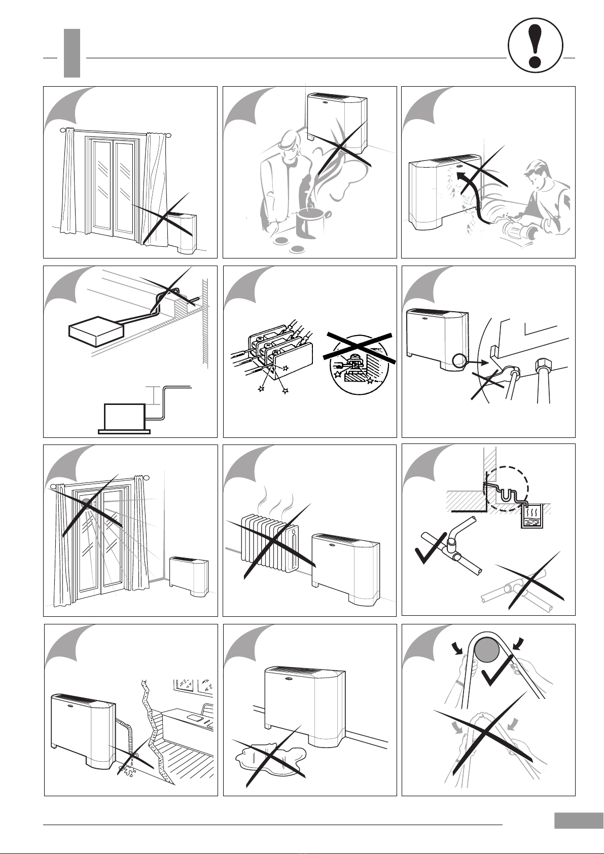
Warnings: avoid ------------------------------------------------------------------------------- 17 - (5)
Dimensions and Weights ------------------------------------------------------------------- (6)
Operating limits -------------------------------------------------------------------------------- (11-12)
Technical data --------------------------------------------------------------------------------- (13-14)
Material supplied ------------------------------------------------------------------------------ (15)
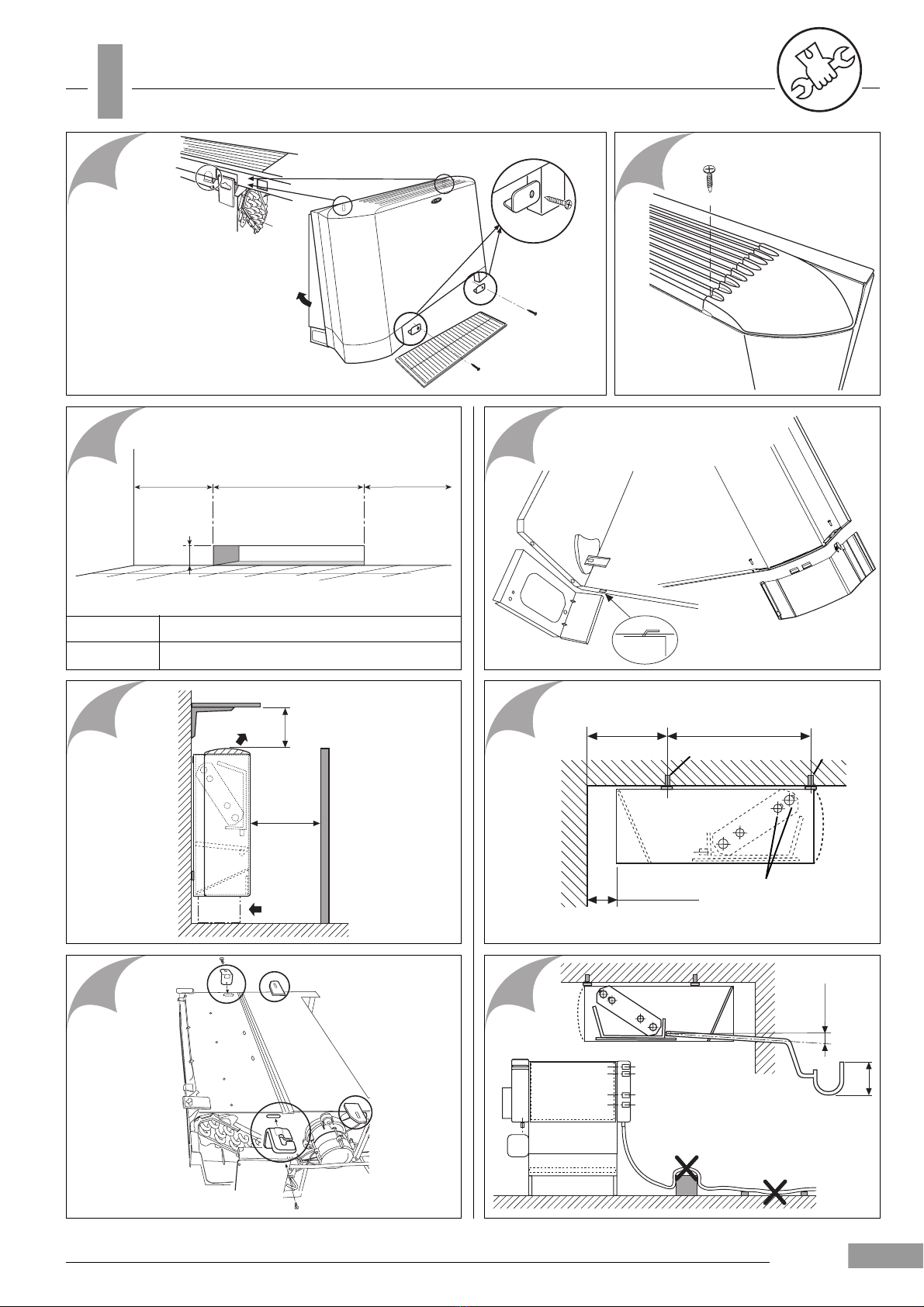
Installation -------------------------------------------------------------------------------------- 18 - (7)
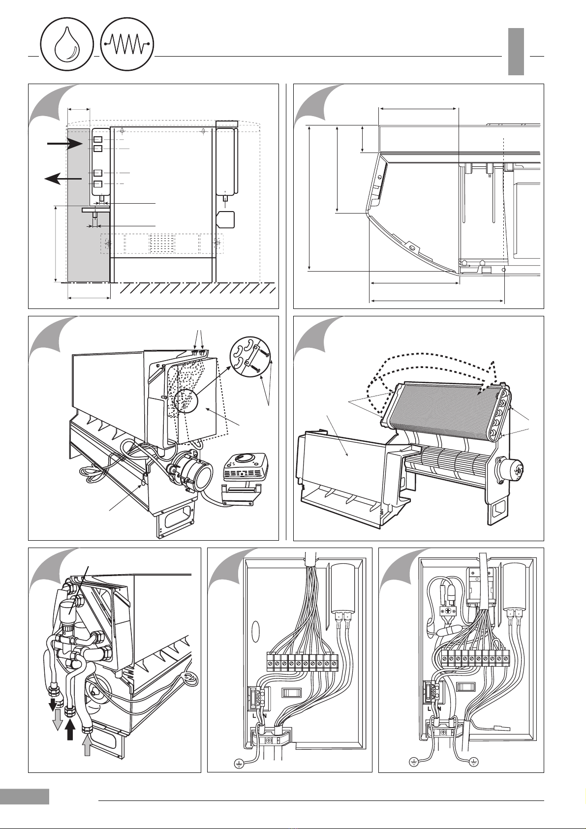
Water connections --------------------------------------------------------------------------- 18-19 - (8)
Electrical connections ----------------------------------------------------------------------- 19 - (8)
Controls ----------------------------------------------------------------------------------------- 19-20-21-22 - (9)
Electric heater --------------------------------------------------------------------------------- 23
Maintenance ----------------------------------------------------------------------------------- 23 - (10)
Contents Page
mm
Indice Pagina
mm
Sommaire Page
mm
Legenda ----------------------------------------------------------------------------------------- 24
Informazioni generali ------------------------------------------------------------------------- 25
Avvertenze: evitare --------------------------------------------------------------------------- 25 - (5)
Dimensioni e masse ------------------------------------------------------------------------- (6)
Limiti di funzionamento ---------------------------------------------------------------------- (11-12)
Dati tecnici -------------------------------------------------------------------------------------- (13-14)
Materiale a corredo --------------------------------------------------------------------------- (15)
Installazione ------------------------------------------------------------------------------------ 26 - (7)
Collegamenti idraulici ----------------------------------------------------------------------- 26-27 - (8)
Collegamenti elettrici ------------------------------------------------------------------------ 27 - (8)
Comandi ---------------------------------------------------------------------------------------- 27-28-29-30 - (9)
Elemento riscaldante ------------------------------------------------------------------------ 31
Manutenzione --------------------------------------------------------------------------------- 31 - (10)
Légende ----------------------------------------------------------------------------------------- 32
Generalités ------------------------------------------------------------------------------------- 33
Attention: eviter -------------------------------------------------------------------------------- 33 - (5)
Dimensions et poids ------------------------------------------------------------------------- (6)
Limites de fonctionnement ----------------------------------------------------------------- (11-12)
Caractéristiques techniques --------------------------------------------------------------- (13-14)
Matériel fourni --------------------------------------------------------------------------------- (15)
Installation -------------------------------------------------------------------------------------- 34 - (7)