Carson RP-300 User manual

RP-300 TELESCOPE
Instruction Manual
50668 005737 1
©2007 CARSON OPTICAL
HAUPPAUGE NY 11788
www.carson-optical.com
MADE IN CHINA
©2009 CARSON OPTICAL
HAUPPAUGE NY 11788
www.carsonoptical.com
MADE IN CHINA
©2009 CARSON OPTICAL
HAUPPAUGE NY 11788
www.carsonoptical.com
MADE IN TAIWAN
©2010 CARSON OPTICAL
HAUPPAUGE NY 11788
www.carsonoptical.com
MADE IN TAIWAN
©2010 CARSON OPTICAL
HAUPPAUGE NY 11788
www.carsonoptical.com
MADE IN CHINA
©2011 CARSON OPTICAL
HAUPPAUGE NY 11788
www.carsonoptical.com
MADE IN CHINA
Carson Optical
35 Gilpin Avenue
Hauppauge, NY 11788-4723
Phone: 631-963-5000
Fax: 631-427-6749
For information, call toll-free: 1-800-967-8427

Introduction
Box Contents
Figures 1-9/Figure Key
Telescope Assembly
•SettingupYourTripod
•AttachingtheEquatorialMount
•AttachingtheCounterweight
•AttachingtheSlowMotionCables
•AttachingtheTelescopeTubetotheMount
•AttachingtheFinderScope
•AttachingtheEyepieces
Balancing the Telescope
•BalancingtheMountinR.A.
•BalancingtheMountinDec.
•AligningtheFinderScope
Calculating Power
UnderstandingCelestialMovement
A Brief Overview of Celestial Coordinates
Polar Alignment
Using the Telescope
•ImageOrientation
•UsingSettingCircles
CareandMaintenanceofYourTelescope
•Cleaning
•CollimationofOptics
•AdjustingtheDiagonalHolder
•AdjustingthePrimaryMirror
•NightTimeStarCollimationTesting
Specications
Warnings
CustomerService
Warranty Information
CongratulationsonyourpurchaseofaCarsonRP-300RedPlanetTMSeries
telescope. This telescope features an easy-to-use design and high perfor-
mance optics that are perfect for amateur astronomers looking to explore
the wonders of outer space. Please read this manual carefully to ensure that
you assemble and use your telescope correctly. When used properly, your
RedPlanetTM telescope should provide years of exciting observations of the
universe.PleasenotethatthisNewtonianReectortelescopewasdesigned
for astronomical viewing and is not recommended for terrestrial use.
IMPORTANT: DO NOT USE YOUR RED PLANETTM TELESCOPE
TO LOOK AT OR NEAR THE SUN! DOING SO WILL CAUSE IN-
STANT AND PERMANENT EYE DAMAGE.
Each box contains the following:
•CompleteOpticalTubeAssembly.
•EquatorialMount.
•Heavy-DutyAluminumTripod.
•9mmKellnerEyepiece(1.25”O.D.).
•20mmKellnerEyepiece(1.25”O.D.).
•CradleRingswithLockKnobs.
•6x30mmFinderScope.
•CounterweightBarwithCounterweight.
•FlexibleCableControlsforBothAxes.
Please unpack your telescope carefully and make sure that all accessories are
included in the box.
3
4-9
10-11
12-13
13
14
14-15
15
16-17
18-22
21
21
22
22-23
3
Table of Contents:

Fig.1 Fig.3
Fig.2
54

Fig.4 Fig.6
Fig.5 Fig.7
76

Key to Figures 1-9:
1. 6x30mmFinderScope
2. Focuser
3. Eyepiece
4. Focus Knobs
5. Optical Tube Assembly
6. CradleRings
7. Dec.FlexibleCable
8. R.A.FlexibleCable
9. OpticalTubeSaddlePlate
10. EquatorialMount
11. Counter Weight Bar
12. Counter Weight
13. CounterWeightLockingScrew
14. TripodLegs
15. DeclinationLock
16. Dec.SettingCircle
17. R.A.SettingCircle
18. LatitudeDial
19. LatitudeTurnScrews
20. EquatorialMountBase
21. EquatorialMountLockingScrew
22. R.A.Lock
23. Focuser Thumbscrew
24. FinderScopeBracketThumbscrew
25. FinderScopeFocusKnob
26. FinderScopeBracket
27. FinderScopeBracketMountingBolts
28. CradleRingLockKnobs
29. CradleRingAttachment
30. CradleRingAttachmentWingNuts
31. TripodTighteningRing
32. Tripod Brace
33. EyepieceHolderSlots
34. Tripod Hook
35. TripodLegLockClosed
36. TripodLegLockOpen
37. DiagonalMirrorTiltScrews
38. DiagonalMirrorHolder
39. PrimaryMirrorLockingScrews
40. PrimaryMirrorTiltScrews
Fig.8
Fig.9
98

AssemblyofyourRedPlanetTelescope:
Setting Up Your Tripod:
Thealuminumtripodcomespreassembledandready-to-use.Removethe
tripod from the box and pull apart the legs. Gently push down the tripod
braces(Fig.7-35)untiltheyareinthelowestposition.Turnthetightening
ring(Fig.7-31)(locatedatthecenteroftheTripodBrace)clockwisetolock
the tripod in the open position. You can then extend the legs to the desired
heightbypullingopenthetaboneachleglock(Fig.7-36),slidingtheleg
down the desired amount and then pushing the leg lock back against the leg
intothelockedposition(Fig.7-35).Repeattheprocesswitheachlegtrying
to keep the tripod as level as possible with the ground. You will notice there
areholesinthetripodlegbraces(Fig.7-33).Thesearedesignedtoholdeye-
pieces when not in use. For added stability you can hang a weight from the
tripodhook(Fig.7-34)locatedatthebottommiddleportionofthetripod.
Attaching the Equatorial Mount:
Removetheequatorialmount(Fig.2-10)fromtheboxandtwistintothe
positionshowninFig.3.Placethebottomofthemount(Fig.3-20)intothe
hole in the top of the tripod head and secure with the mount locking screw
(Fig.3-21).Pleasebecarefultomakesurethatthemountissecurelyat-
tached to the tripod.
Attaching the Counterweight:
Attachthethreadedendofthecounterweightbar(Fig.2-11)intothethreaded
holeintheequatorialmount(Fig.2-10).Removethesafetyscrewfromthe
endofthecounterweightbarandsetasideforamoment.Slidethecounter-
weight(Fig.2-12)ontothebarandtightendownusingthescrewontheside
ofthecounterweight(Fig.2-13).Becarefulnottodropthecounterweight.
Itisquiteheavyandcouldharmyouordamageyouroorifdropped.Do
notworryaboutthepositionofthecounterweightjustyet.Wewillpositionit
properlylater.Replacethesafetyscrewattheendofthecounterweightbar.
Attaching the Slow Motion Cables:
Locatethetwoslowmotioncables(Fig.1-7,8).Loosenthescrewattheend
ofeachcablesothatitdoesnotprotrudethroughthehole.Slidetheshort
cableontoeithersideoftheR.A.shaft(Fig.1-8)(locatedatthebottomof
themount)andtightendownwiththelockingscrew.Youcanplacethecable
on either side depending on which side is most comfortable for you to use.
SlidethelongercableontotheDec.shaft(Fig.1-7)(locatedatthetopofthe
mount)andtightendownwiththelockingscrew.Theseslowmotioncables
willallowyoutomakenepointingadjustmentstothetelescopeinboth
R.A.anddeclination.Thiswillbediscussedinmoredetaillater.
Attaching the Telescope Tube to the Mount:
Removethetwocradlerings(Fig.1-6)fromthebox.Therearetwoholes
inthetopoftheequatorialmount(calledtheopticaltubesaddleplate(Fig.
2-9)).Placethethreadedscrewatthebottomofeachcradlering(Fig.6-29)
through one of these holes and secure it using the included washer and wing
nut(Fig.6-30).Attachandsecuretheothercradleringinthesameway.
Makesurethatthecradleringlockknobs(Fig.6-28)arebothonthesameside.
Unscrewthelocks(Fig.6-28)oneachcradleringandopenthemboth.Care-
fullyremovetheopticaltubeassembly(Fig.1-5)fromthebox.Gentlyrest
theopticaltubeintothecradleringswiththefocuser(Fig.1-2)towardsthe
front. The cradle rings should be roughly in the center of the tube. We will
balance this later. Close the cradle rings around the telescope and secure by
tighteningthecradleringlockknobs(Fig.6-28).
Attaching the Finder Scope:
Therearetwonderscopebracketmountingbolts(Fig.5-27)locatedatthe
frontendoftheopticaltube.Removethenutsandsetaside.Placethender
scopebracket(Fig.5-26)ontothemountingboltsandtightendownsecurely
totheopticaltube.MakesurethebracketisfacingforwardasshowninFig.
5.Slidethenderscope(Fig.1-1)intothebracketfacingforward.Tighten
downthenderscopebracketthumbscrews(Fig.5-24)tosecurethender
scope in place.
Attaching the Eyepieces:
InserttheKellner20mmeyepiece(Fig.1-3)intothefocuser(Fig.1-2)and
tightendownusingthefocuserlockingscrew(Fig.4-23).
YouhavenowcompletedtheassemblyofyourRedPlanetTM telescope.
Wewillnowneedtomakethenecessaryadjustmentsinordertouseyour
telescope properly.
1110

Balancing the Telescope:
Balancing the Mount in R.A.:
To reduce stress on the mount, the telescope should be balanced on the polar
axis(SeeFig.2).Instructionsonhowtodosoareasfollows:
•LoosentheR.A.lockknob(Fig.3-22)andpositionthetelescope
offtoonesideofthemount(youmayneedtoremovetheR.A.slow
motioncable(Fig.1-8)temporarily).Thecounterweightbar
(Fig.2-11)shouldbeparalleltotheground.
•Releasethetelescopegraduallyandseewhichsideitfallstowards.
To avoid accidental damage, do not let go of the telescope completely.
•Loosenthecounterweight(Fig.2-12)andpositiontheweightsothat
thetelescopeandcounterweightremainstationary(paralleltothe
oor)ontheirown.
•Tightenthecounterweightintoplace.
Balancing the Mount in Dec.:
TopreventsuddenmovementwhentheDec.lock(Fig.3-15)isloosened,the
telescopemustbebalancedonthedeclinationaxis(SeeFig.2).Instructions
on how to do so are as follows:
•LoosentheR.A.lockknob(Fig.3-22)andpositionthetelescope
offtoonesideofthemount(youmayneedtoremovetheR.A.slow
motioncable(Fig.1-8)temporarily).Thecounterweightbarshould
be parallel to the ground.
•TightentheR.A.lockknob(Fig.3-22)toholdthetelescopeinplace.
•LoosentheDec.lockknob(Fig.3-15)androtatethetelescopeuntil
the tube is parallel with the ground.
•Releasethetelescopegraduallyandseewhichwayitwillrotate.To
avoid accidental damage, do not let go of the telescope completely.
•Loosenthecradlerings(Fig.1-6)andslidetheopticaltubeforward
or backward as needed until it remains stationary and parallel to the
ground on its own.
•Tightenthecradleringssecurelyaroundtheopticaltube.
•LoosentheR.A.lockknob,returnthetelescopetoitsupright
position and retighten.
Aligning the Finder Scope:
Thelowpowerandwideeldofviewprovidedbythe6x30mmnderscope
(Fig.5-1)providesaquickandeasywaytosightanobjectpriortolooking
throughthehigh-powertelescope.Thenderscopemustrstbeproperly
aligned with the telescope in order to work properly. This alignment is best
performedduringthedaylight.Followthestepsbelowtoalignyournder
scope properly:
•PlacetheKellner20mmeyepiece(Fig.4-3)intothefocuser
(Fig.4-2)ofthetelescope.
•LoosenboththeR.A.lock(Fig.3-22)andtheDec.lock(Fig.3-15)
so that the telescope swings freely along both axes.
•Pointthemaintelescopeataspeciclandobject200yardsormore
away.LockdowntheR.A.andDec.axes.Turntheslowmotion
cables(Fig.1–7,8)untiltheobjectiscenteredinthetelescopeeld.
•Nowlookthroughthenderscopeandloosenortightenthender
scopebracketscrews(Fig.5-24)untilthecrosshairsarecenteredon
thesameobject.Focusbyturningthenderscopefocusknob
(Fig.5-25)untiltheimageinthenderscopeissharpandclear.
•Checkthealignmentatnighttimebyrepeatingthisprocesswitha
brightstarorthemoon.Makeanynecessaryadjustments.
Nowthatyournderscopeisproperlyaligned,anyobjectcenteredinyour
nderscopeshouldalsobecenteredinyourtelescope.
Calculating Power:
Themagnicationofatelescopedependsonboththefocallengthofyour
telescope as well as the eyepiece you use. There is a simple formula you can
usetodeterminethemagnicationyouareusingatanygiventime.Simply
divide the focal length of the telescope by the focal length of the eyepiece.
For example, if you are using the 20mm eyepiece with your TP-300 telescope
the power would be:
Power = 900mm / 20mm = 45x
Usinganeyepiecewithasmallerfocallengthwillincreasethemagnication
ofyourtelescope.Itisalwaysbesttostartatthelowestmagnicationcon-
guration.Thewidereldofviewmakesiteasiertospotfarawayobjects.
Onceanobjectiscenteredinyoureldofviewyoucanswitchtothehigher
powercongurations.
1312

UnderstandingCelestialMovement:
Inordertogetthemostenjoymentoutofyourtelescopeitisnecessaryto
knowthebasicsofhowcelestialobjectsmoveacrossthesky.Duetothero-
tationoftheearth,celestialobjectsappeartomovefromEasttoWestacross
thesky,muchliketheSun.Youwillnoticethismovementasanobjectin
yourtelescopeeldofviewwillslowlymoveacrosstheeldandoutof
view.Continuousadjustmentisneededtokeepanobjectintheeldofview.
This will be explained in more detail later.
Manypeoplechooseto“star-hop”whenusingatelescope,aquickandrela-
tivelyeasywaytostart.Thisisamethodofusingeasilyidentiablestars
andconstellationstoserveasreferencepointstondotherobjectsinthesky.
Amoreadvancedandprecisemethodoflocatingspeciccelestialobjectsis
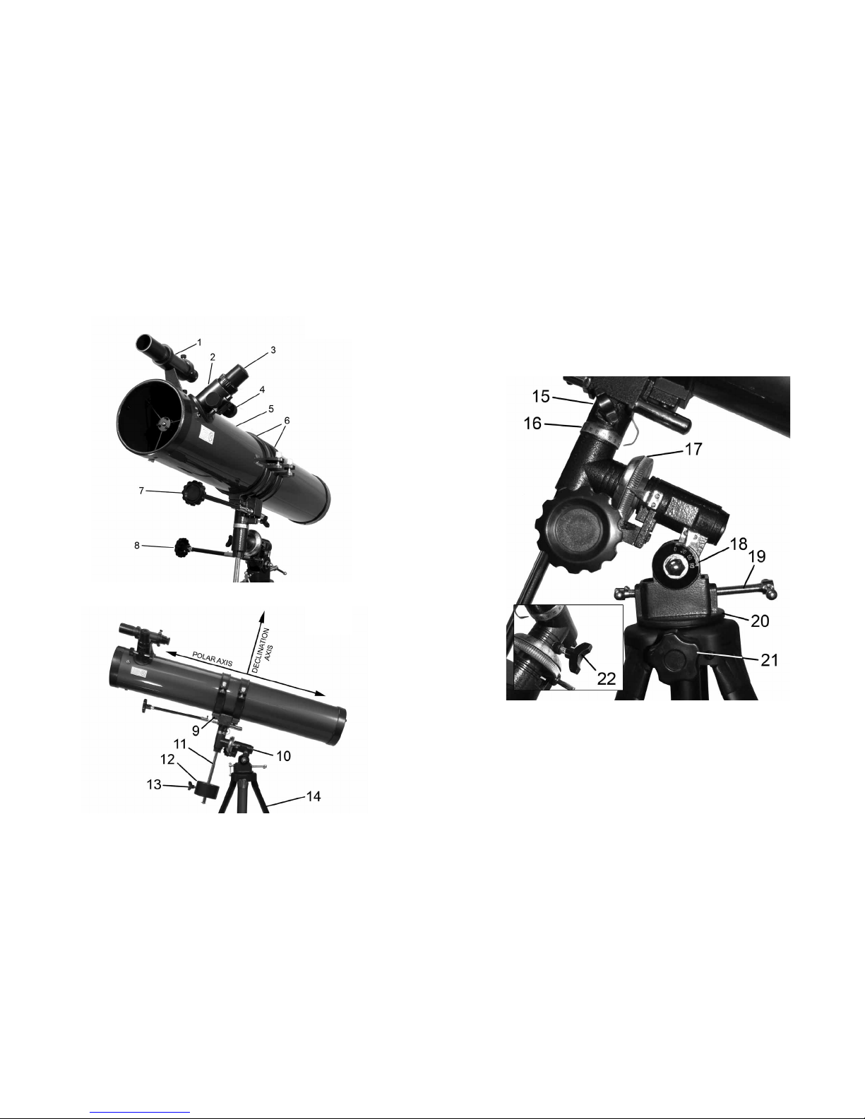
byusingsettingcircles(Fig.3-16,17)locatedonyourequatorialmount(Fig.
2-10)tondthecelestialcoordinatesofthatparticularobject.
A Brief Overview of Celestial Coordinates:
Astronomersuseasystemof“celestialcoordinates”similartotheEarth’s
latitudeandlongitudesystemtohelplocateobjectsinthesky.Allcelestial
objectsaremappedona“celestialsphere”,animaginarysphereofarbitrary
sizeconcentricwiththeEarth.IfyouextendtheEarth’srotationalaxisto
innity,bothNorthandSouth,thepointsatwhichthisaxisintersectsthe
celestialsphereareknownastheNorthCelestialPoleandtheSouthCelestial
Pole.IfyouprojecttheEarth’sequatoroutwardtothecelestialspherethis
wouldbeknownasthe“CelestialEquator”.
Theequivalenttolatitudelinesonthecelestialsphereareknownaslinesof
“Declination”,or“Dec.”forshort.Theselinesaremeasuredindegrees,min-
utesandseconds.Declinationreadingsnorthofthecelestialequatorcarrya
“+”sign,whilereadingssouthofthecelestialequatorcarrya“-“sign.Ob-
jectslocatedonthecelestialequatorhavea0°0’0”Declination.TheNorth
CelestialPolehasa+90°0’0”DeclinationwhiletheSouthCelestialPolehas
a-90°0’0”Declination.ThestarPolarisislocatedveryneartheNorthCeles-
tialPoleandhasa+89.2°Declination.
Theequivalenttolongitudelinesonthecelestialsphereareknownaslines
of“RightAscension”or“R.A.”forshort.Theselinesaremeasuredinhours,
minutesandsecondsstartingatthe“zero”lineofR.A.whichpassesthrough
theconstellationPegasus.Thereare24primarylinesofR.A.locatedat15°
intervalsalongthecelestialequator.RightAscensioncoordinatesrangefrom
0hr0min0secto(butnotincluding)24hr0min0sec.
EverycelestialobjecthasacorrespondingR.A.andDec.coordinate.Given
the proper coordinates, you can use the setting circles on your telescope
mounttolocateanycelestialobject.Thecoordinatescanonlybeusedifthe
telescopeisrstalignedwiththeNorth(orSouth)CelestialPole.
Polar Alignment:
If the telescope is accurately aligned with the celestial pole, very little dec-
linationadjustmentwillbenecessarytotrackacelestialobject.Mostofthe
trackingcanbedoneusingtheRightAscensioncable(Fig.1-8).
To line up your telescope with the pole:
•Makesuretheequatorialmountislockedinthe“home”position,
meaning that the optical tube assembly is parallel to the correspond-
ing portion of the mount below it and that the declination axis is
straightupanddownwiththecounterweight(Fig.2-13)init’s
lowestposition.Forreference,theequatorialmountinFig.2isin
the home position.
•Loosentheequatorialmountlockingscrew(Fig.3-21)sothatthe
entiretelescope(withmount)rotatesfreelyonthetripod.
•RotatetheentiretelescopeuntilthepolaraxispointsdueNorth.If
you are not sure which direction is North, locate Polaris and point the
polar axis towards it. Polaris is less than one degree away from the
Celestial North Pole and is accurate enough for polar alignment.
•Ifneeded,levelthemountbyadjustingthetripodlegsaccordingly.
•Determinethelatitudeoftheareayouarein.Usethelatitudeturn
screws(Fig.3-19)totiltthetelescopeuntilthepointerindicatesthe
correctlatitudeonthelatitudedial(Fig.3-18).
•Thennetunethelatitudeturnscrews(Fig.3-19)untilPolaris
appearsinthecenterofyourtelescopeeldofview.
•DonotmovethetelescopeinR.A.orDec.whilepolaraligning.
Theseadjustmentsshouldremainlocked.
•IfyouliveintheSouthernHemisphere,youshouldfollowthese
stepsbutpointthepolaraxisdueSouthandlocateSigmaOctantis
instead of Polaris.
1514

Your telescope is now polar aligned for the area you are using it. You will
needonlytopointthetelescopeNorth(orSouthintheSouthernHemisphere)
when using it from now on. You will only need to repeat the polar alignment
if you move to a different location and your latitude has changed.
Using the Telescope:
Once you have properly assembled, balanced and aligned your telescope you
arenallyreadytostartusingit.
•Tolocateanobjectusingthetelescope,rstloosentheR.A.lock
(Fig.3-22)andDec.lock(Fig.3-15)allowingthetelescopetorotate
alongbothaxes.Lookthroughthenderscope(Fig.1-1)tosightthe
objectyouarelookingforandcenteritinthenderscope
cross-hairs.Youmayneedtofocusthenderscopebyturningthe
nderscopefocusknob(Fig.5-25).Thenre-tightentheR.A.and
Dec.locks.
•Itisbesttousethelowestpowereyepiece(theKellner20mm
eyepiece)atrst.Thisallowsforawidereldofviewmakingit
easiertolocateobjects.Oncetheobjectiscenteredintheeldof
viewyoucanswitchtheeyepiecetohighermagnications.
•Oncetheobjectiscenteredintheeldofview,turnthefocusknobs
(Fig.4-4)ontheeyepiecefocuser(Fig.4-2)untiltheimageisclear
and sharp.
•Youwillnoticethattheobjectyouareviewingwillslowlymove
acrosstheeldofview(causedbytherotationoftheEarth).You
willneedtoturntheR.A.exiblecable(Fig.1-8)tokeeptheobject
centered.
Image Orientation:
Youwillnoticethattheimageyouseethroughyournderscopeandtele-
scopeareinverted(upsidedown).ThisisnormalforNewtonianReector
telescopes.
Using Setting Circles:
Thesettingcircles(Fig.3-16,17)onyourequatorialmountcanbeusedto
locatehardtondcelestialobjects.Followtheinstructionsbelowtousethe
setting circles effectively:
•Makesureyourtelescopeisassembledproperlyandpolaraligned.
•Lookupthecelestialcoordinatesofaneasytospotobjectlocated
nearbytotheobjectyouseekonastarchartoratlas(notincluded).
•Centerthiseasytospotobjectintheeldofviewofyourtelescope.
•RotatetheR.A.settingcircle(Fig.3-17)onyourtelescope’smount
byhanduntilthepropercoordinatelinesupwiththeR.A.indicator.
YouwillnoticethattheR.A.settingcirclehastwosetsofnumbers.
The top numbers are for the Northern hemisphere. The bottom
numbersarefortheSouthernhemisphere.Oncecompleteyour
setting circles are now calibrated. You are now ready to locate the
hardtondobject.
•LoosentheDec.lock(Fig.3-15)andmovethetelescopein
Declinationuntiltheindicatorpointstothecorrectcoordinate.
Re-tightentheDec.Lockwhennished
•LoosentheR.A.lock(Fig.3-22)andmovethetelescopeinR.A.un-
tiltheindicatorpointstothecorrectcoordinate.Re-tightentheR.A.
lockwhennished.
•Lookthroughthenderscope(Fig.1-1)toseeifyouhavelocated
theobjectyouarelookingforandcentertheobjectinthecrosshairs
ofthenderscope.
•Lookthroughthetelescopeeyepieceandtheobjectyouaresearching
forshouldbecenteredintheeldofview.
•Thisprocessmustberepeatedeverytimeyousetupyourtelescope.
1716

There are many conditions that may affect your ability to focus or observe
celestialobjectsclearly.
•Brightlylitareas(lightpollution)willmakeitdifculttoseefaint
objectsinthesky.Itwillalsomakeitdifcultforyoureyestoadjust
tothedark.Youshouldtryandndadarkareaandallowyoureyes
toadjusttothedarkbeforemakingobservations.Usingaredltered
ashlighttoviewchartsandyourtelescopecomponentsisrecom-
mended to preserve your night sight. The best viewing conditions
are when the sky is inky black.
•Hazyskies,pollution,cloudsandmoisturecanallaffecttheclarityof
your viewing image.
•Avoidtouchingtheeyepieceoropticaltubewhilelookingthrough
the telescope. The vibrations caused by this contact will cause the
objectyouarelookingattomove.Youshouldalsomakesurethat
the surface you place your telescope on does not vibrate or move as
thiswillalsocauseyourviewingobjecttomove.
•Youshouldavoidsettingupyourtelescopeinsidearoomlooking
through an open window. The difference in air temperatures may
result in a blurry image.
•Viewingthroughaclosedwindowmightalsoresultinadistortedim-
age due to the varying densities of window glass.
•Avoidviewingobjectsthatarelowonthehorizon.Objectsthatare
higher up in the sky will appear much sharper.
•Suddenchangesintemperaturemaycausecondensationtoappear
on the optical components of the telescope. It is best to set up your
telescopeaheadoftimeandthenwaitwhilethetelescopeadjuststo
the new temperature before using it.
CareandMaintenanceofYourTelescope:
Cleaning:
•Alwaysreplacedustcoversandlenscapswhennotinuse.Thiswill
minimize the amount of dust and debris that gets into your telescope.
•Cleaningshouldbeperformedonlyifabsolutelynecessary.Ifdust
hasbuiltupontheopticsuseasoftcamel’shairbrushorpressurized
air to gently remove it.
•Ifdewcollectsontheopticsofyourtelescopeormoisturecondenses
inside the optics, remove all accessories and place the telescope in a
dry, dust free environment and point the telescope downward. This
should help eliminate the moisture.
•Avoidtouchingthesurfaceofthemirror.
•Donotattempttotakeapartyourtelescopetocleanit.
Collimation of the Optics:
Theinternalopticsofthetelescopehavealreadybeen“collimated”or
“aligned”atthefactory.However,roughhandlingofthetelescopemay
knock the optics out of collimation, resulting in poor optical performance.
Please refer to Fig. 10 to better understand the internal layout of your
telescope. To determine if your telescope needs collimation perform the
following steps:
•Removetheeyepiece(Fig.1-3)fromthefocuser(Fig.1-2)andturn
thefocusingknob(Fig.1-4)untilthetubeisatitsinnermostposition.
•Pointthetelescopeataplainbackgroundandthenpeerthroughthe
emptyfocuser.Youshouldseeaseriesofconcentriccircles(See
Fig.11).Theoutermostcirclebeingareectionoftheprimarymir-
ror(withthreemirrorclips).Theinnercircleisthediagonalmirror,
which should be precisely centered inside the primary mirror. You
shouldseethereectionofyoureyeinthediagonalmirror.
Adjusting the Diagonal Holder:
If the telescope is properly collimated you should see the primary mirror
(SeeFig.10)andthreeclipsintheirentirety.Iftheprimarymirrorisnot
centeredproperly(SeeFig.12)youwillneedtoadjustthediagonal
mirror(SeeFig.10)tocorrectthis.Loosenthediagonalmirrorsothat
youcanmovethediagonalholder(SeeFig.10)withyourhand.Tiltthe
diagonal holder until the entire primary mirror is visible and carefully
retighten the screws to lock it into place. If necessary, turn the three screws
slightlytomakeneadjustments.
1918
Fig.10 Fig.11

Adjusting the Primary Mirror:
If the telescope is properly collimated you should see the diagonal mirror
(SeeFig.10)attheexactcenteroftheprimarymirror.Ifthediagonal
mirrorappearsoff-center(SeeFig.12)youwillneedtoadjusttheprimary
mirror(SeeFig.10)locatedontheoutsidelower-endofthemaintube.To
dothisyouwillrstneedtoloosentheprimarymirrorlockingscrews(Fig.
9-39).Thesearethescrewsthatareushagainstthesurfaceofthetelescope.
ThenalternatelyloosenandtightenthePrimaryMirrorTiltScrewsuntilthe
diagonal mirror is centered inside the primary mirror. The primary mirror
screwsareeasilyidentiedbecausetheystickoutfromthesurfaceofthe
telescope.Oncetheadjustmentiscomplete,re-tightentheprimarymirror
locking screws.
Night Time Star Collimation Testing:
•Totesttheaccuracyofyourcollimation,equipyourtelescopewith
the 20mm eyepiece and focus on a moderately bright star.
•Withthestarcenteredintheeldofview,slowlyturnthefocus
wheel(Fig.1-4)untilthestarisoutoffocus.
•Ifproperlycollimated,youshouldseeaseriesofconcentriccircles
aroundablackcenterdot(Fig.13-C).
•Ifthecirclesarenotconcentricandtheblackdotisnotcentered
(Fig.13A)youwillneedtomakeadjustmentstotheprimarymirror.
Loosentheprimarymirrorlockingscrews(Fig.9-39)andusethe
R.A.andDec.cablestomovethecirclestotheedgeofthetelescope
eldofview(Fig.13-B).Thenturntheprimarymirrortiltscrews
(Fig.9-40)untiltheblackdotmovestothecenteroftheimagewith
theconcentriccirclesradiatingfromit(Fig.13-C).Oncecentered,
tighten down the locking screws.
Specications:
OpticalDesign: NewtonianReector
Aperture: 114mm(4.49”)
FocalLength: 900mm(35.43”)
FocalRatio: 7.89
FinderScope: 6x30mm
Eyepiece1: Kellner20mm
Magnication1: 45x
Eyepiece2: Kellner9mm
Magnication2: 100x
Mount: Equatorial
Weight: 19.7 lbs.
Warnings:
•Neverusethistelescope(oritsviewnder)tolookdirectlyatornear
thesun.Viewingthesuncancauseinstantandirreversibleeyedamage.
•Alwayssupervisechildrenwhenusingthistelescope.
•Donotleavetelescopeunattendedatanytime.Untrainedadultsor
children may not be familiar with the correcting operating procedure.
•Donotpointthetelescopeatthesunevenwhenyouarenotlooking
through it. This will cause internal damage to the telescope.
•Handlethistelescopewithcare.Roughhandlingmightknockthe
internal optical components out of alignment.
2120
Fig.12 Fig.13

CustomerService:
We will be happy to help you with any problems you may experience
while using your telescope. Please call our toll-free customer service line
at 1-800-967-8427.
Warranty Information:
This Carson product is warranted to be free from defects in material and
workmanshipforaperiodofoneyearfromdateofpurchase.Duringthis
period Carson will, at its option and without charge, either repair any part
or assembly of parts found to be defective in material or workmanship, or
replace this Carson product with a Carson product of comparable value and
condition,subjecttothelimitationsandexclusionsnotedherein.
This warranty extends to the original purchaser only and is not assignable
ortransferable.Itshallnotapplytoanyproductthathasbeensubjectto
misuse, abuse, negligence or accident, or to any defects or damage directly or
indirectly caused by the use of unauthorized replacement parts and/or service
performed by unauthorized personnel.
Thiswarrantygivesyouspeciclegalrights,andyoumayalsohaveother
rightswhichcouldvaryfromstatetostate.Somestatesdonotallowlimi-
tations on the life of an implied warranty and/or do not allow excluding or
limitingincidentalorconsequentialdamages.Ifso,theabovelimitationsor
exclusions may not apply to you.
Warranty Procedure:
Provide proof of purchase. A receipt or other dated proof of purchase must
be included with merchandise being returned for a warranty claim to be pro-
cessed.
Call or write for authorization. Before returning any product for a warranty
claim,aReturnAuthorization(RA)numbermustbeobtained.Nomerchan-
disewillbeacceptedwithoutanRA,andfailuretoobtainanRAwillprevent
ordelayprocessingofthewarrantyclaim.ToobtainanRAcall631-963-
5000,orwritetoCarsonWarrantyService,35GilpinAve,HauppaugeNY
11788 with a description of the problem. Include your name, address and
telephone number.
Packagethereturncarefully.Shipperswillnotreimbursefordamagesdueto
insufcientpackaging,evenifthemerchandiseisinsured.PrinttheRAnum-
ber prominently on the top of the package.
Prepayshipping.Insurethepackage.SendittoCarsonWarrantyService,35
GilpinAve.,HauppaugeNY11788.Merchandisemustbeshippedprepaid.
CarsonwillnotacceptmerchandiseC.O.D.
2322
Other manuals for RP-300
1
Table of contents
Other Carson Telescope manuals

Carson
Carson EVERGLADE SS-560 User manual

Carson
Carson RP-200 User manual

Carson
Carson RP-400 User manual

Carson
Carson RP-100 User manual

Carson
Carson Skelescope SK-100 User manual

Carson
Carson RP-100 User manual

Carson
Carson skyseeker JC-1000 User manual

Carson
Carson Skyseeker JC-200 User manual

Carson
Carson Sky Chaser-450 User manual

Carson
Carson Skyseeker JC-1000 User manual

Carson
Carson RP-400 User manual

Carson
Carson AIM MTEL-50 User manual

Carson
Carson Skyseeker JC-200 User manual

Carson
Carson RP-300 User manual

Carson
Carson Skyseeker JC-200 User manual

Carson
Carson SkyRunner SV-350 User manual

Carson
Carson Skelescope SK-100 User manual

Carson
Carson SkyRunner SV-350 User manual