+
+
B
A
T
T
E
R
Y
P
O
S
I
T
I
V
E
+
+
F
U
E
L
o
r
I
G
N
3
0
A
m
a
x
BATTERY
I S O L A T O R
B
A
T
T
E
R
Y
N
E
G
A
T
I
V
E
-
-
M O T O R S P O R T . c o m M A D E I N U . K .
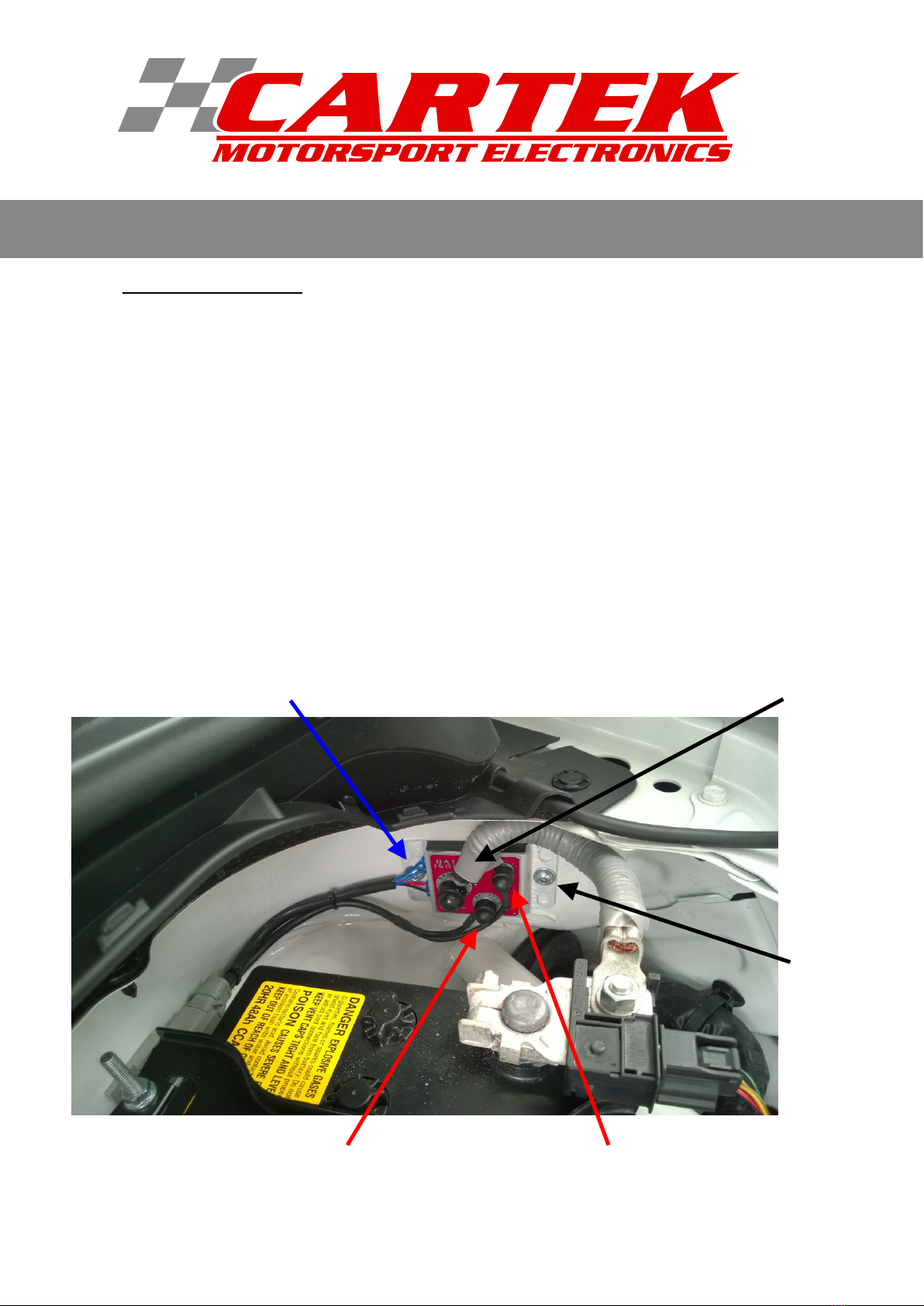
INSTALLATION
Step 2. SWITCH CONNECTIONS
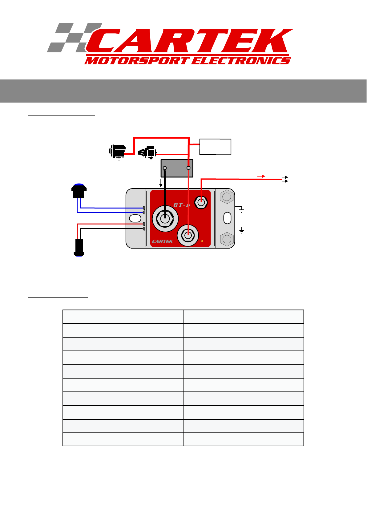
The Isolator can be controlled by any number of on-off/kill switches although the usual configuration is one
internal on-off button and one external kill button.
The internal switch needs to be of a latching type, either toggle or pushbutton, such that the ON position
makes the circuit while the OFF position breaks the circuit. When using the internal pushbutton
switch with integrated LED, it is important to observe the polarity, i.e. Red to Red, Black to Black.
The external kill switch should be of the non-latching, momentary action, normally-closed (NC) type and
connected across the two Blue wires of the external switch circuit. If required, multiple kill switches/devices
can be incorporated by connecting in series. If only a single internal on-off switch is to be used with no
external switch then the external circuit needs to be complete by joining the two Blue wires together. If any
wire connection becomes broken due to fatigue or accident then the Battery Isolator will automatically
switch OFF killing the engine and disconnecting the battery.
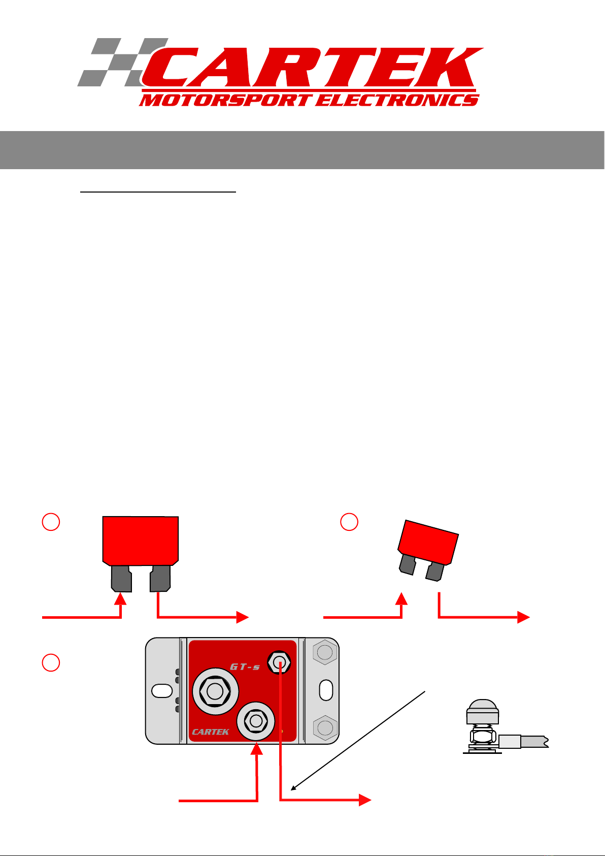
WARNING: Do not test the Internal Button by passing power through it, this will damage it. It will only
work correctly when connected to the Battery Isolator.
+
+
INTERNAL ON/OFF
BUTTON WITH
INTEGRAL LED
EXTERNAL KILL
BUTTON
ADDITIONAL KILL
BUTTON
5
Battery Isolators allow for
an external 'kill' button to be mounted on
both sides of a race car for instant access and
maximum safety.