Carts Vermont 20 User manual

Thank you for choosing carts Vermont! We take pride in our high
standards of workmanship and quality. Your cart was made with the
finest quality materiels available. With proper care, it will give you
many years of dependable service.
For your convenience, we have installed all T-nuts and pre-assembled
some metal components. Once again, We at carts Vermont thank you.
Should you have any comments or questions, please contact us.
Model 20
Home & Garden Cart
CARTS
VERMONT

Model 20 Home and Garden Cart Assembly
These instructions will show how you assemble your Model 20 Cart in an easily followed
sequence. You should look over the hardware rst and arrange it so it is easily accessible.
We have made every effort to be sure that holes line up; however, due to normal expansion of wood
parts, holes may not appear to line up. This is easily corrected by making sure that all bolts are
loose, and by working a nail or awl into the hole so all parts line up enough to thread bolts in.
We recommend that bolts be started by hand to reduce the possibility of damaging threads in
T-nuts. It is also a good idea to have another person available during assembly—an extra pair of
hands may come in handy if parts needed aligning.
Tools you will need: nail or awl, regular screwdriver, and an adjustable or a 7/16” wrench.
Parts List
Rear end protector (1) (pre-installed)
Front end protector (1) (pre-installed)
Front panel
edge protector (pre-installed)
Handle (1)
Right handle sleeve (1)
Left handle sleeve (1)
Leg stand (1)
Right bottom angle (1) (pre-installed)
Left bottom angle (1) (pre-installed)
Weld dump front assembly (1)
Aluminum angles (2)
Axle (1)
Wheels (2)
Bottom panel (1)
Right side panel (1)
Left side panel (1)
Dump front panel (1)
2

Model 20 Home and Garden Cart
Overview
3

Step 1
A. Install 3/4" bolts and attach to lock nuts. (Lock nuts on bottom side.)
B. Place “Left side Panel” on left side of bottom panel and fasten with two 1/2" bolts as shown
in Figure 1. Note: Logo will be on the outside of the cart.
C. Place “Right side panel” on right side of bottom panel and fasten with two 1/2" bolts in the
same locations as shown for left side in Figure 1.
D. Place “Welded dump front assembly” on front end of the bottom and side panels.
E. Place “Aluminum angles” on the inside of the cart, align the holes with those in the side pan-
els and welded dump front assembly, insert 1-1/4" bolt through the bottom holes in the alumi-
num angles, and fasten with a lock nut on outside of cart as shown in Figure 1.
Figure 1.
4

Step 2
A. Insert “Axle” through one “Wheel”. Insert a cotter pin through the hole at the end of the axle
and spread ends to form a “Y”.
B. Hold the other end of the axle and slide the remaining “wheel” onto the axle. Insert a cotter
pin through the hole at the end of the axle and spread ends to form a “Y”. See Figure 2 for
reference.
Figure 2
5

Step 3
A. Turn the cart over as shown in Figure 3.
B. Spread apart the wheels so that they come to rest against the cotter pins. Place the axle and
wheels on the cart and align the holes. Fasten these clamps with 5/8" bolts as shown in Figure 3.
C. Slide the “Leg stand” over the sides of the cart. Align and thread 1-1/4" bolts through holes
“A” and “B” into T-nuts (on both sides of cart) as shown in Figure 3.
D. Tighten all bolts on the bottom of the cart.
Figure 3
6

Step 4
A. Turn cart over as shown in Figure 4.
B. Place “Right handle sleeve” over right side panel ( wide side of handle sleeve to inside of
cart.) The wide side of the handle sleeve must be placed between side panel and aluminum
angle. Insert 1-1/4" bolt through top hole of aluminum angle and fasten with lock nut on out-
side of cart. See Figure 4 for reference.
C. Repeat Step 4 for the left side.
D. Slide “Handle” into handle sleeves. (You may need to tap the handle in with a hammer.)
Align holes in handle with those of the left handle sleeve (handle may be placed in one of two
positions), then fasten with self-tapping screws. Repeat for right side. Note: with handle in ex-
tended position, use rear and center holes for self-tapping screws. See Figure 4 for reference.
E. Slide “Front panel” down between front assembly and aluminum angles. Adjust aluminum
angles by moving them in or out so that the panel will slide in and out easily, then tighten the
four bolts that attach the aluminum angles to the cart. Recheck dump front panel to see that
it slides freely.
F. Tighten all the bolts on the cart.
Your cart is now ready to use!
7

MAINTENANCE AND CARE
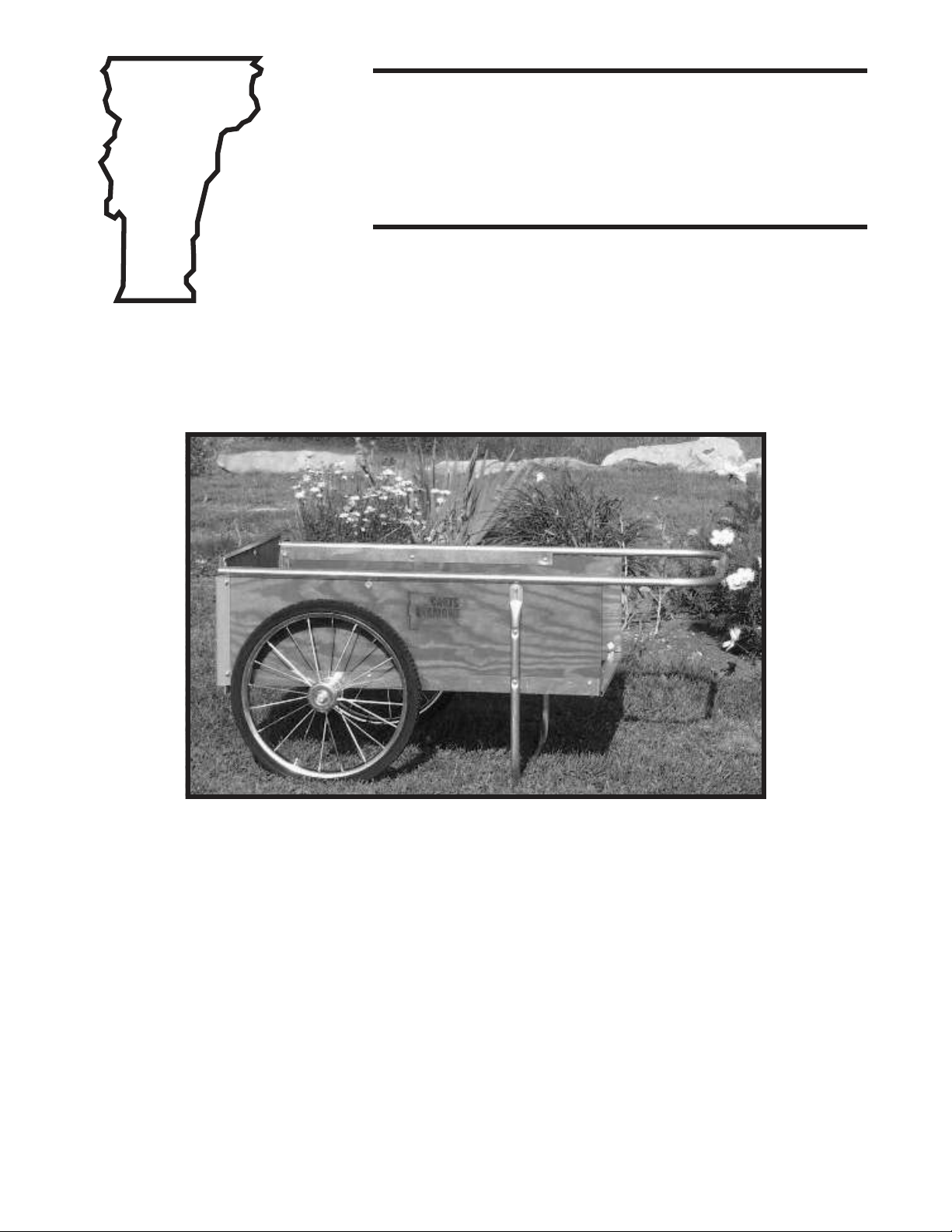
FOR YOUR MODEL 20 HOME AND GARDEN CART
• Do: Protect your cart from sever weather whenever possible
• Do: Renish your cart yearly with a good grade of exterior water base stain.
• Do: Tighten hardware periodically; it will loosen under normal use.
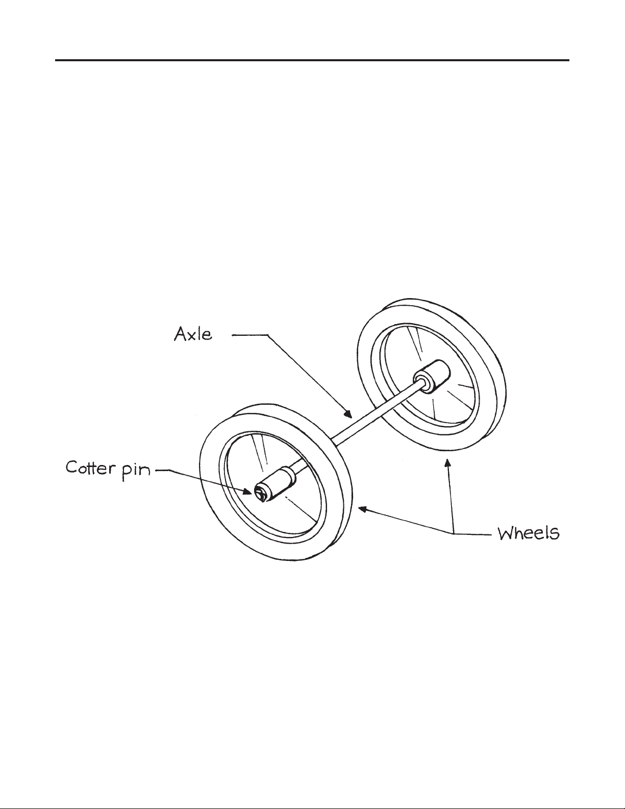
• Do: Lubricate wheel ball bearings with a light machine oil such as “3 in 1” two drops in
both sides of bearings once a year. Caution: Do not over-oil; over-oiling attracts dirt and
dust.
• Do: Periodically check tire pressure. Overtime, tires will normally lose air pressure. Inate
to a maximum of 35 PSI. Caution: Do not over-inate.
HOME AND GARDEN CART SAFETY:
Your cart is designed to have a balance point which allows you to move loads with ease. Due to
this design you must observe a few simple safety precautions.
• Never walk down a hill or grade pulling the cart behind you. You could trip or fall, losing
control of the cart.
• Always use cation when traversing on hill sides.
• Never sit or stand in or on the cart.
• Always balance your load.
• Never push a loaded cart over curbs and logs.
• Never tow the cart with a motorized equipment or vehicles.
SPECIAL CAUTION: When re-inating tires, inate to a maximum of 35 PSI.
Over-infation of tires could cause serious injury.
CARTS
VERMONT
Call Toll Free: 1-800-732-7417 w1-802-626-4178 wFax 1-802-626-6191
P.O. Box 54 wLyndonville, VT 05851
www.cartsvermont.com
This manual suits for next models
1
Table of contents
Other Carts Vermont Outdoor Cart manuals