CARVIN BASS KIT ASSEMBLY INSTRUCTIONS
The components in this kit are the same as those used in Carvins high quality custom shop B4 and B5
basses. All holes are drilled, making it a simple step by step process to assemble your bass. Before you start
assembling your bass, check the component check list to make sure that you got everything. It's also a good
idea to read the complete instructions before getting started. Have fun!
KIT COMPONENT CHECK LIST:
Bolt-on bass neck
Tuning keys
Body
Combination bridge & tailpiece
H50N humbucking bass pickups (2)
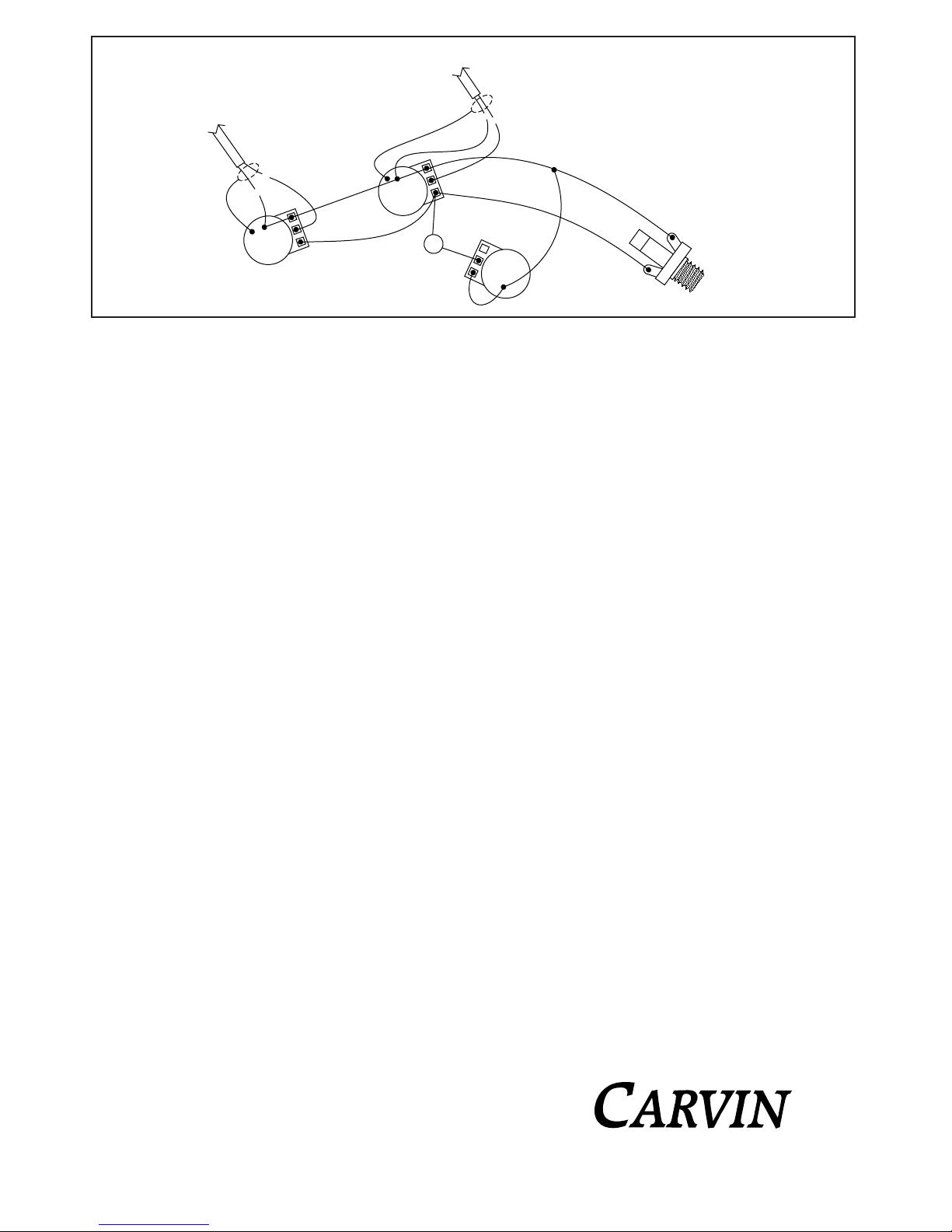
Wiring harness
K2 knobs
BP1 rear electronics cover with threaded inserts
JP1C jackplate
NP4C neckplate
E2C strap buttons
Copper foil shielding & solder
Carvin bass strings
TR1 truss rod adjusting wrench
TOOLS REQUIRED FOR ASSEMBLY
Small slot head screw driver for installing knobs
Screwdriver with a good quality #1 phillips tip
Screwdriver with a good quality #2 phillips tip
Small adjustable wrench for tightening tuning keys
Wire cutters for cutting strings
Needle nose pliers for wiring
Soldering iron for soldering pickup leads
Hammer for installing threaded back plate inserts
TUNG OIL (or) GLOSS FINISH
A tung oil finish is by far the easiest method for a novice to achieve his
own high quality finish with a minimum of equipment and experience. If
you decide to go with a gloss finish, we recommend that you use
lacquer as opposed to polyurethane, because lacquer is easier to spray,
has faster drying time and reduces dust problems. Lacquer also sands
easier between coats and polishes easier. There are several good
books, including the "Guitar Player Repair Guide" available in the Carvin
catalog with instructions on how to do your own gloss finish.
MATERIALS FOR YOUR TUNG OIL FINISH
At Carvin we have used and experimented with most brands of tung oil
finishes and have found Minwax brand to be the best in every respect.
One pint is enough to do a couple of guitars and is available at Home
Depot or most home improvement type hardware stores for under $10.
You will also need about 6 sheets of extra fine sand paper (between 220
and 320 grit), a 1" paint brush, about 4 pads of extra fine steel wool
(0000), a few small rags and a small bottle of furniture oil (Old English
red oil or lemon oil).
SANDING
Before you start applying the tung oil, you should first thoroughly sand
the rounded edges smooth on the top and bottom of the body, so that
there are no imperfections. You can do the same for the neck. Before
applying the tung oil, blow the fine sanding dust off of the body and neck
or use a tack rag to remove the dust.
APPLYING THE TUNG OIL
Pour a small portion of the tung oil into a small clean container.
Immediately replace the cap on the can of tung oil so that the tung oil
does not go bad. Take a 1" wide paint brush and apply the tung oil into
all of the interior routed holes on the body, including the neck pocket.
Now brush the tung oil onto the entire remaining surface of the body and
neck. It is not necessary to coat the ebony fingerboard, although it won't
hurt it. If you apply the tung oil onto the fingerboard, wipe off as much of
the excess as possible within 5 minutes before it starts to dry. Wipe off
the excess on the complete neck or body within 10 minutes. Now let the
neck or body dry for at least 5 hours before recoating with more tung oil.
You can hang the neck up to dry with a piece of wire through one of the
tuning key holes. To hang the body to dry, run a piece of wire or string
through one of the neck bolt holes. After the neck or body dries inspect
it for sanding imperfections before applying another coat. Sand any
imperfections out now with 320 grit sand paper. When applying your
2nd, 3rd, and final 4th coat, it is not necessary to apply tung oil into the
neck cavity or control cavity. If you wish, you can also apply these coats
with a small rag instead of a brush. Apply these coats fairly heavy, so
that they penetrate into the wood pores, but always wipe off the excess
within 10 minutes. It is best not to rush the tung oil process. At Carvin,
we apply 2 coats of tung oil the first day and 2 coats the next day about
6 hours apart. On the 3rd day you can steel wool your finish to
perfection. Rub hard using 0000 grade steel wool on the top and bottom
of the body, but don't rub too hard on the sharp edges and corners,
because you will rub through the tung oil finish. If you do rub through,
you can easily recoat this area and lightly rub it with steel wool after the
tung oil dries. After you have inspected your complete neck and body
for imperfections, you can wipe on a thin film of (Old English) furniture oil
ad wipe off the excess. Do not apply the furniture oil in the control cavity
area, otherwise the copper foil may have trouble sticking. The furniture
oil will bring out a nice sheen in the wood and give your bass a smooth
sexy feel.
NOW LETS BOLT THIS THING TOGETHER
CARVIN TUNING KEYS
The large tuning key holes going through the headstock are 9/16" and
the little holes on the rear of the headstock are drilled 1/16". To install
the Carvin tuners, place one tuner into one of the 9/16" holes on the rear
of the headstock and finger tighten a washer and nut on the top of the
tuning key. Finish installing the remaining tuners. Now line up the small
holes in the tuners with the 1/16" drilled holes on the rear of the
headstock. Screw in the small #2 x 3/8" long wood screws into the 1/16"
holes using a #1 phillips head screw driver. Finish by tightening the
nuts with a 5/8" socket or small adjustable wrench.
STRAP BUTTONS
Use a #2 phillips head screwdriver to install the 2 strap buttons to the
body. Make sure that you start the screws straight into the 7/64" drilled
holes. Do not over tighten the screws. Just snug them up to the body.
COPPER FOIL SHIELDING
Line the control cavity with the self adhesive copper foil. Be careful that
you do not cut your fingers with the edges of the copper foil. Stick the
large contoured piece of copper foil on the bottom of control area first.
Then adhere the 1 1/2" wide x 16" long foil onto the sides of the control
area. Fold a portion of the side wall foil onto the rear of the body where
the rear control covers sits. This will make contact with the aluminum
foil underneath the rear electronics cover plate. Make sure that you
press the foil tightly onto the wood. At Carvin we use the end of a piece
of 3/8" wooden dowel to press the copper down. If the foil ever peels
away from the wood, it may cause a temporary short in your bass. Use
a knife to cut the copper foil out of the control holes and jack hole area.