Case Communications 3611 User manual

3611
Ethernet
to
Serial Converter
Manual

This page left blank Intentionally

3611 Ethernet to Serial Converter
Index
Rev 1.3
Section Index Page
1 Web Management 1.1
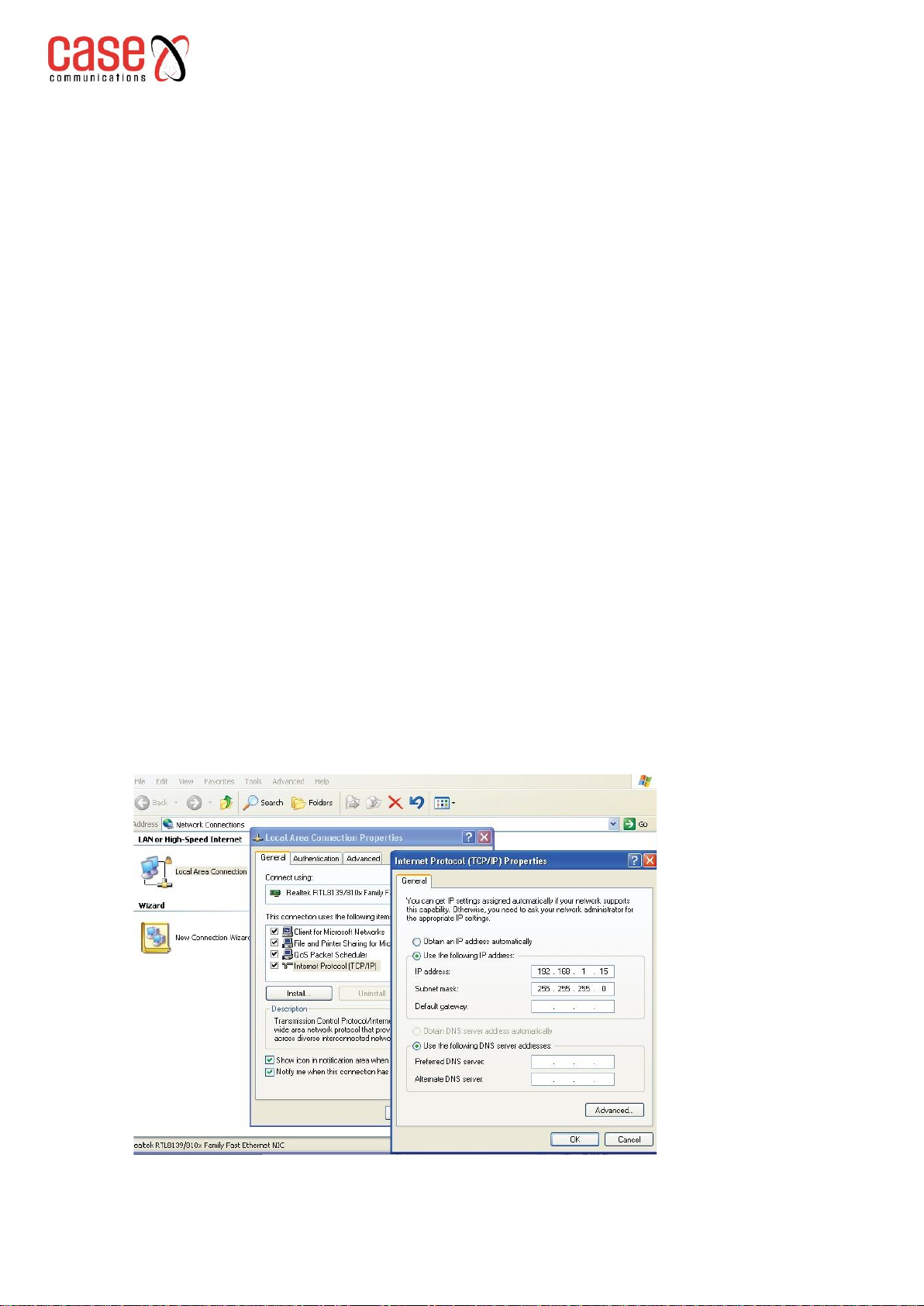
1.1 Network settings 1.1
1.2 Function menu 1.2
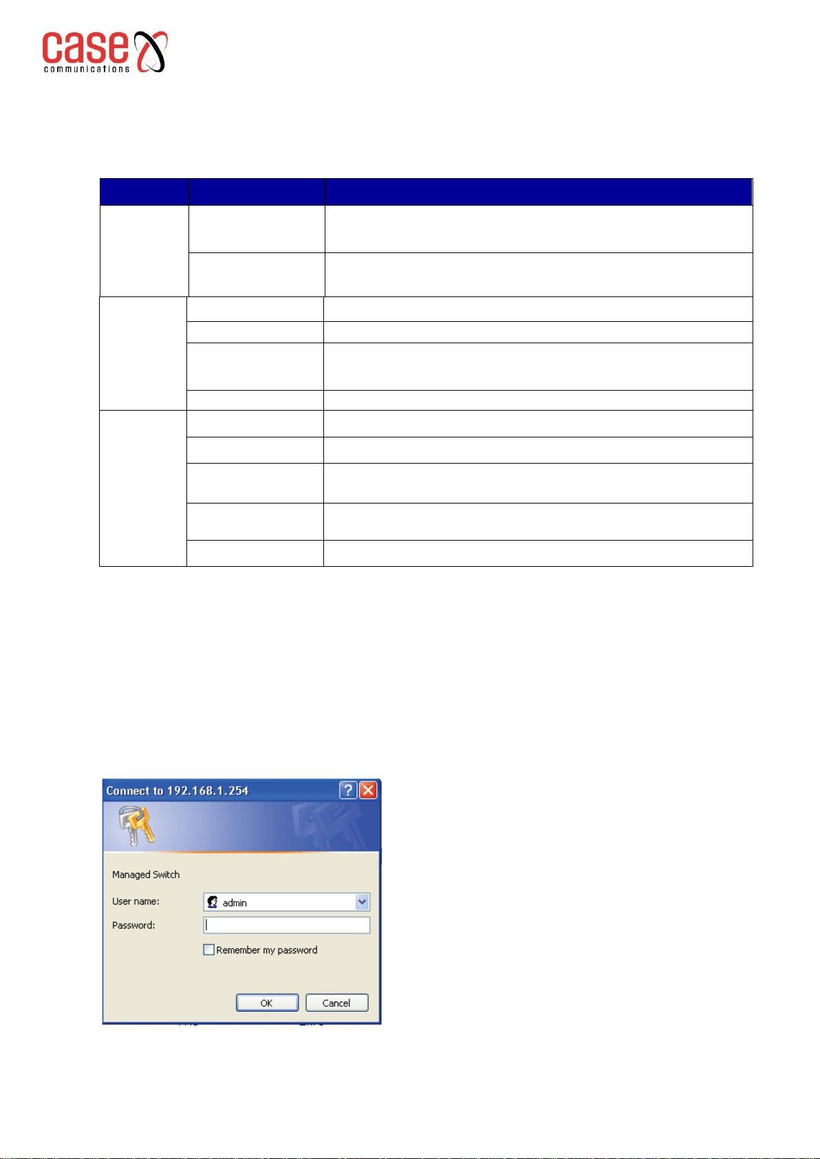
1.3 Logging in via the Web interface 1.2
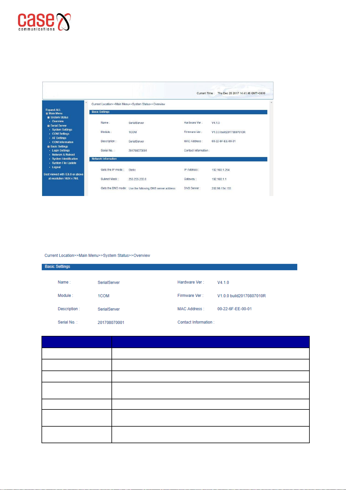
1.3.1 Device Information 1.3
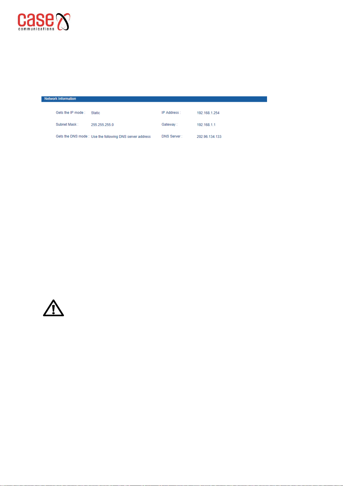
1.3.2 Network Information 1.4
1.4 Serial Server 1.5
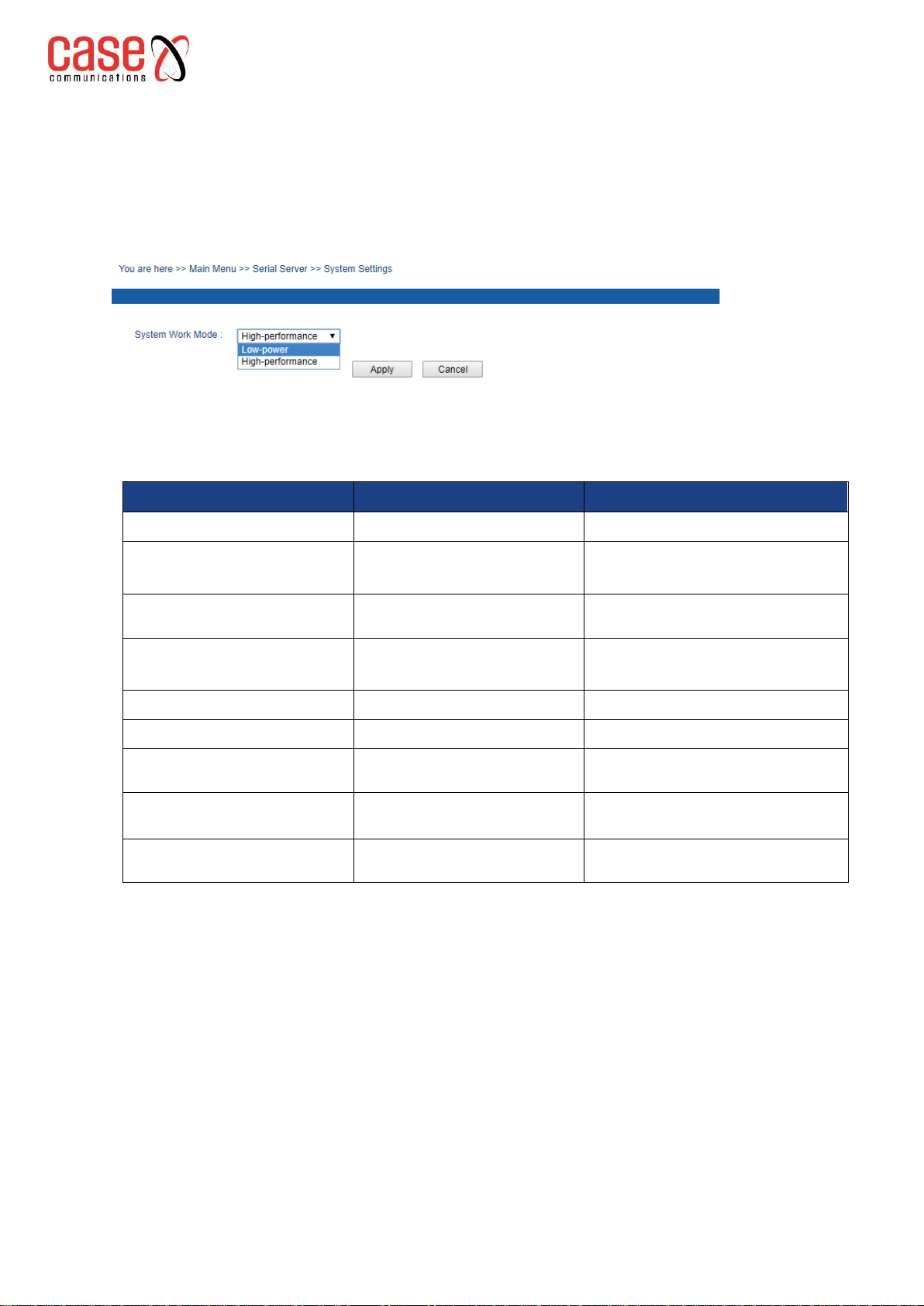
1.4.1 System Settings 1.5
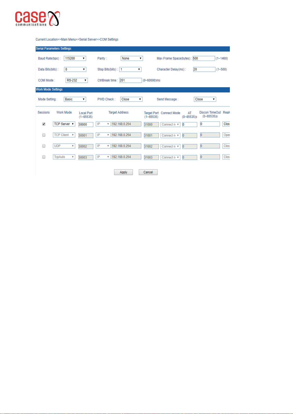
1.4.2 Serial port parameters setting 1.5
1.4.3 Working Mode Settings 1.7
1.4.4 AT Command Mode 1.11
1.4.5 COM Information 1.13
1.5 Basic Settings 1.14
1.5.1 Login Settings 114
1.5.2 Network & Reboot 1.14
1.5.3 System Identification 1.16
1.5.4 System File Update 1.17
1.5.5 System Logout 1.18
2 Frequently Asked questions 2.1
2.1 Login Problems 2.1
2.2 Configuration Problems 2.1
2.2.1 The TCP Socket communication cannot communicate properly? 2.1
2.2.2 Serial server cannot communicate properly, the 3611 data is wrong? 2.1
2.2.3 PC with straight-through cable losing Ping packets 2.1
2.2.4 Receiving “!”from the 3611 with a limited local connection 2.1
2.2.5 Serial server link LED does not light? 2.1
2.2.6 Virtual Serial Port unable to link using the VSP Manager 2.1
2.2.7 Data is garbled using the serial port? 2.2
2.2.8 Why is the serial server disconnected after a period of connection? 2.2
2.2.9 Need to change the MAC Address? 2.3
2.2.10 Can a serial server support multiple computer communications? 2.3
2.2.11 Connecting two computers via their virtual ports. 2.3
2.2.12 Can the serial server communicate after crossing the network segment? 2.3
2.2.13 In Serial Mode the LEDS are all on but communications fail 2.3
2.2.14 The 3611 supporting virtual serial communications inTCP client mode 2.3
2.2.15 Can we use the 3611serial server via a wireless router? 2.3
2.2.16 How do we wire the RS485 Serial port? 2.3
2.2.17 How many RS-485 terminal nodes can the serial server support? 2.3
2.2.18 Unable to save the 3611 Parameters 2.4
2.2.19 Can the serial server be used in pairs? 2.4
2.2.20 Running multiple RS-485 devices with only 1 IP Address 2.4
2.2.21 The 3611 creates a virtual serial port, causing the computer to crash? 2.4
2.2.22 Can the baud rate of the serial server support 921.6k? 2.4
2.2.23 How should I use the 3611 debug the device? 2.4

3611 Ethernet to Serial Converter
Symbols Used in this Manual
Rev 1.3
Symbols used in this manual
Format
Description
Indicates a potentially hazardous situation which, if not avoided, could result in
equipment damage, data loss, performance deterioration, or unanticipated results.
NOTICE is used to address practices not related to personal
injury.
Indicates a potentially hazardous situation which, if not avoided, could result in
death or serious injury.
Calls attention to important information, best practices and tips.
NOTE is used to address information not related to personal
injury, equipment damage, and environment deterioration.
The tips for correct configuration and operation.
Revision History
Version No.
Date
Revision note
01
July 1, 2011
Layout Adjustment
02
October 1, 2014
Manual Maintenance
03
January 3, 2017
Add password verification function

Section 1 Page 1
3611 Ethernet to Serial Converter
Web Management
Rev 1.3
1. Web Management
Before configuring your Case Communications 3611, please make sure your PC has
installed the correct software as shown below
The lowest requirements of user PC is as follows:
▪Installation operation system (as Windows 10 / 8 / XP/2000, Windows 7etc)
▪Installation Ethernet card
▪Install Browser explorer (IE6.0 or higher version etc)
▪Install and startup TCP/IP protocol
1.1 Network settings
The 3611’s default IP address: 192.168.1.254, subnet mask: 255.255.255.0.
When accessing the 3611 server through the WEB browser. The IP address of the serial device
server and PC must be in the same Local Area network. You can modify PC’s or serial device
server’s IP address to make sure that they are in the same Local Area Network.
Follow the steps below
Modifying your PC’s IP address.
Step 1 Click Start->Control panel->network
connections->Local area Connection->Properties-
>Internet protocol(TCP/IP)Setting PC’s IP address: 192.168.1.X (X is expect 254, from 2 to
253).
Step 2 Click “OK”, IP address modified successful. Configure your IP Address in Windows as shown
below.:

Section 1 Page 2
3611 Ethernet to Serial Converter
Web Management
Rev 1.3
1.2 Function menu
The 3611 main menu includes 3 parts:
These are shown in the table below
Menu
Page layout
Function
Device
information
Basic information
Display device name, description, Module, Serial No., Hardware
Ver, Firmware Ver and MAC address etc
Network
information
Display IP Address, subnet mask, gateway
address, DNS etc
Serial
Server
System Settings
System Work Mode: Low-Power and High -performance
COM setting
Serial Parameter setting and working mode setting
AT command
settings
AT Command Mode Settings: 1. I/O port trigger;
2. Ctrl Break trigger; 3. Character strings trigger (Hex)
COM information
Statistics Information and Link Information
System
tools
Login Settings
Login name and password
Network & Reboot
Network setting and Device Reboot
System
Identification
Modify Basic information: Module, Name,
Description, serial NO. and Contact information.
System File
Update
Factory Default, Update Configuration File from
Local PC and Upgrade Firmware from LocalPC
Logout
System Logout
1.3 Logging in via the Web interface
Before access serial server through IE browser, please make sure PC and device in the same
Local Area Network or can access through router. Follow these steps.
Step 1 Click your browser with right key, click “Properties”, empty temporarily files and history
record.
Step 2 Open your browser, input the IP address of the serial server in the address bar, click
“Enter”, enter into user name and password interface as shown below.
Step 3 Input your user name and password, “Enter”, enter into serial server interface as shown
below.

Section 1 Page 3
3611 Ethernet to Serial Converter
Web Management
Rev 1.3
The Web setting interface is divided into these sections:
•Title area
•Menu bar
•Setting area. Click menu of the mean bar, can enter into relevant
If you enter your user-name or password input incorrectly 3 times, you will need to start
again from the beginning.
1.3.1. Device Information
Device information includes the device name, device description, hardware version, software
version, MAC address as shown below.
Option
Meaning
Module
Network Identification
Name
Serial number
Description
The description of device’s features, like as used key place.
Contact information
The contact information for the person who maintains the
Device. This can be configured in system information.
MAC address
Hardware address, 48bits(6 bytes,), 16 hexadecimal, it is unique
Hardware version
The current hardware version information, please note the
limit of software version to hardware version
Firmware version
The current software’s version information, upgrade
software version will have more function

Section 1 Page 4
3611 Ethernet to Serial Converter
Web Management
Rev 1.3
1.3.2. Network Information
The 3611 supports 2 modes of operation for IP Addressing. DHCP and static IP address.
When using the DHCP function, the IP address of the device can be obtained from a DHCP Server.
If you need to connect to the Domain Name System, please fill in the Gateway and DNS address. As
shown below
IP Address
The IP address is a 32 bits length address. The device that connects to the Internet, IP address has
2 options configured:
•net-id
•host-id, IP address can set in static IP or DHCP.
Subnet Mask
The Subnet Mask is an IP address with32 bit number, that divides the IP address into 2 parts:
Subnet addresses and host computer addresses.
Default Gateway
The default gateway in the Host computer is usually called the ‘Default Route’. The Default
Route is the route chosen by the network when the destination address of IP packets is on a
different network. All packets not on the local subnet will use the default route.
DNS Address
The DNS is the Domain Name Server. It resolves the name of a destination to an IP address
internet can identify. If the 3611 needs to visit some Host devices, it needs to use the DNS server
to resolve an IP address.
Notice
If we need the 3611 to “automatically obtain an IP address”, please ensure the
DHCP Server is in the same network and can obtain an IP address. After
“automatically obtaining an IP address”, the 3611 needs to use the software
manager to search the device and obtain the IP address for the device.

Section 1 Page 5
3611 Ethernet to Serial Converter
Web Management
Rev 1.3
1.4 Serial Server
1.4.1. System Settings
The serial device server supports low-power and high-performance working mode optional,
as shown below.
1.4.2. Serial port parameters setting
Serial interface setting menu:
Serial interface setting menu
Data optional
Function Description
COM Mode
RS-232full
Serial work mode
duplex/RS-422 full duplex/RS-
485 half duplex
Baud rate(bps)
300-115200 (10 baud
rate optional)
Baud rate choice
Parity bits
None, Even, Odd,
Mark, Space
Checkout choice
Data bits(bits)
5, 6, 7, 8
The parameter of serial
Stop bits(bits)
1, 1.5, 2
The last of the data package
Max Frame Space (bytes)
1-1460
The length of frame from serial data
to Ethernet data.
Character Delay(ms)
1-500
The time space from serial data to
Ethernet data
CtrlBreak default output
time(ms)
0-60000
Logon to the serial server’s Web interface, click [Serial Setting], choose the required
configuration in the corresponding drop-down menu.
Serial settings Web interface as shown below. When the serial server communicates with the
serial interface device, serial server’s setting is as follows:

Section 1 Page 6
3611 Ethernet to Serial Converter
Web Management
Rev 1.3
These configuration options are explained below,
COM Mode: RS-232 full duplex/RS-422 full duplex/RS-485 half duplex
Baud rate: It is a parameter to check the communication speed. It shows to transfer how many
bits in 1 second. For example, 300 baud rate means have 300 bits transferred in 1 second.
Parity bits: It is a simple method to checkout fault in serial communication, have 4 types:
Even, Odd, Mark, Space
Data bits: It is a parameter to check the actual data bits in communication. The standard is 5,
6, 7, 8.
Stop bits: The last bit of the single Packet, Typical bit is 1, 1.5 and 2. Serial device server’s
stop bit is 1, 2.
Max frames: The frame length that serial interface data convert into Ethernet data, within the
range of setting time, it forwards when data is equal to or longer than the setting frames.
Available setting value ranged from1 to 1460.
Character Delay: The wait time when serial interface send data do not 1 data frames. If up to
this time and do not have data, then send automatic.
CtrlBreak default output time: Setting CtrlBreak default output time

Section 1 Page 7
3611 Ethernet to Serial Converter
Web Management
Rev 1.3
1.4.3. Working Mode Settings
Configuration
menu
Data option
Description
PWD check
Open, Close
After the device is connected with the remote client, the peer client
needs to send the authentication password to the device. After the
password is verified, the client can communicate
with the device.
Send Message
IP, Name, Close
The infmormation sent after the device is connected to the peer
client.
Sessions
1-4
Working mode
Basic mode
TCP Client
TCP Server
UDP
TcpAuto
Select the serial port working mode.
The default mode is closed
Advanced
mode
TCP Server
UDP
Local port
1-65535
Session1 default is 30000, Session4 default is 30003, between them,
add step by step
Target address
Default is
192.168.0.254
Target port
1-65535
Session1 default is 31000, Session4 default is
31003, between them, add step by step
Connect mode
Connect trigger Immediately / data
Default immediately is connect
AT
0-65535 s
Default is 0
Disconnect Timeout
0-65535 s
Default is 300
RealCom
Open/Close
Default is Close
When password verification is enabled, only users with "admin" account privileges can send / receive
messages using this device.
▪The first data sent by the peer client to the device defaults to the checkpassword.
▪Verification password is "admin" account password.
▪If the password is entered incorrectly, re-establish the connection and then re-enter the password.
Sessions: Each serial port of serial device servers can support 1-4 sessions. It means serial port
of serial device server send the received data to Ethernet through socket. More than one of the
sessions means serial port of serial device server sends the received data to Ethernet through
more than one socket. Sessions enable to use by checking the corresponding box.

Section 1 Page 8
3611 Ethernet to Serial Converter
Web Management
Rev 1.3
Basic Mode
1. TCP Client
On the TCP Client side, the 3611 server will connect to TCP/IP network equipment, such as a
PC. Its necessary to setup the 3611 serial device to connect to the IP address and TCP port
number to enable a connection. After creating a socket, the 3611 device will send the data
received from each serial port through the socket On the contrary, the data received from
socket will be sent to the corresponding serial port.
TCP Client setting option: [Target address], [Target port], [Connect mode], [AT] and [Discon
timeout]
The explanation of these setting is as follows:
[Local port]
The configuration is the same TCP server, default is 0~65535.
[Target address]
The IP address or domain name address that device will connect, both of them can correspond
the host computer address on the Internet
[Target port]
The TCP port number that serial device server will connect
[Connect mode]
Connection mode has 2 types: Immediately and Data trigger
▪Immediately: When serial device server has power supply, it will connect immediately, if
connection cut off, it will connectimmediately.
▪Data trigger: Once serial device server receive the data, it will connect immediately.
[AT]
Serial device server send the AT package accord the setting time, if no response continue 3
times, will be cut off. If set to “0” this means this function closed, the range is 0-65535
second, default is 0 second.
[Disconnect Timeout]
Setting the inactive time for automatic cut off, if data transfer is inactive, the connection will cut
off. If its set to “0”, means this is disabled.The range is 1-65535s. Default is 300s
The figure below is the configuration interface for TCP Client Mode.
Session 1 sets the local address available for the router. “192.168.0.254”, the “Target Port”
connected to the serial port is the host computer 192.168.0.254”31000 port.
Connection mode is ‘Connect now’, ‘Discount timeout’ is 300 seconds, note the connection
to pure TCP Client, TCP Server, UDP or TCPAuto mode.
Please close RealCom. Session 3 is setting the Internet address available for the router
“www.test.com”(the choice this time is DNS)the “Target Port” connected to serial port is
host computer ”www.test.com” 31002 port, Connection mode is Immediately, Disconnect
timeout is 300 seconds, click “Apply’, setting successful.

Section 1 Page 9
3611 Ethernet to Serial Converter
Web Management
Rev 1.3
2. TCP server
TCP Server, Passive connect, one pivotal parameter is [Local port], have relationship with other
setting, need combine setting.
[Local port]
The serial server provides a TCP port which can be connect to by other TCP/IP devices. The
TCP port can have a relationship with the 3611 server’s serial interface.
The figure below is the TCP Server configuration interface. Session 1 sets the local port to 30000,
an external TCP port connects through this port. The connection / disconnect timeout is 300
seconds. Click “Apply”, setting successful as shown below.
3. UDP
Under the UDP configuration, the 3611 server can be set to server and also client. The relevant setting
is “Local port”, “Target address” and “Target port”. The 3611 can support point to point and multicast
UDP. The configuration setting is the same as TCP
4. TCP Auto
In this Mode, the 3611 can act as a server or client. Before setting this Mode, please ensure the
configuration parameters are correct. When you enable server mode, client mode isautomatically
disconnected.
5. RealCom Mode
RealCom Mode support TCP Server, UDP and TcpAuto these 3 types, Choose "open" or "close"
to enable this function under RealCom. After opening RealCom, users can make connections
through Windows Hyper Terminal. Typically, RealCom needs to open.

Section 1 Page 10
3611 Ethernet to Serial Converter
Web Management
Rev 1.3
Advanced Mode
1. TCP server
In this mode, the serial device server is set to ‘TCP Server’, and the network manager can
choose 0-4 channel connections at the same time. The configuration mode is shown below:
2. UDP
In this mode, the Target address is an address pool. All of the addresses in this pool can
connect with the 3611. The network manager can choose 0-4 channels to connect at the same
time.

Section 1 Page 11
3611 Ethernet to Serial Converter
Web Management
Rev 1.3
1.4.4. AT Command Mode
By setting “the AT order Mode”, users can enter into AT Command Mode.
There are 3 ways to enter into AT Command Mode, firstly, I/O port trigger, secondly,
Ctrl+Break trigger, thirdly, Character strings trigger (Hex).
Way to AT Order Mode
Meaning
I/O Port Trigger
The default trigger mode, through the hardware
into the AT command mode (Pin 9 low access to the device into the AT
command mode)
Note: I/O trigger mode is suitable for modular products and not for
products with housings.
CtrlBreak trigger
When openingthis mode, click “Ctrl + Pause Break”to enter the AT
Command Mode.
Character strings trigger(Hex)
Entering the corresponding character strings for the serial port assistant to
enter into AT Command Mode.
[I/O port trigger]
By triggering the corresponding pin, you can enter the AT command setting mode. By default,
pin 24 is high. If set to a low level, you can enter AT Command Mode through I/O port trigger.
[CtrlBreak trigger]
Open Virtual Serial Port, click “Ctrl+PauseBreak”, then open the Web page of the 3611 serial
server, click [Serial Server/AT Settings] to enter into AT Command Mode page.
[Character strings trigger (Hex))]
By setting “Character” in “Character Strings Trigger (Hex)”. “Serial Settings”, this allows
predefined characters to be sent via the serial port and into AT Command Settings Mode. By
setting "Ctrl+PauseBreak" and "Character Strings Trigger (Hex)", either one of these options
can allow the network manager to enter the AT Command Mode.
Step 1 After entering AT Command Mode", then open the Hyper Terminal to execute AT command,
as shown below.

Section 1 Page 12
3611 Ethernet to Serial Converter
Web Management
Rev 1.3
Step 2 Select the computer, on the Windows interface, click "Start/All
Programs/Accessories/communication", run a terminal emulation program to create a new connection.
Step 4 Select a serial port.
Select a serial port under” New
Connection” (ensure the chosen
serial port is the port connected
to the 3611, and has a
configuration cable). Click
“OK”.
Step 5 Set the serial port parameters. As shown to
the left.
▪Set the “Bits per second ”to 115200bit/s,
▪“Data bits” is 8, “parity” is None,
▪“Stop Bits” is 1,
▪“Flow Control” is None.
Click “OK” button to enter to “Hyper Terminal”
Window
Step 3 Using Hyper Terminal in Windows for
example, as shown to the left. Type in a new
name for the connection in the text box "name",
then click the "OK" button

Section 1 Page 13
3611 Ethernet to Serial Converter
Web Management
Rev 1.3
1.4.5. COM Information
The main function of serial port information: Display incorrect data statistics and connection
information that send by serial port.
Step 6 As shown to the left , click
“Ctrl+Break”, at the same time
click “Enter” until blinking cursor
appears on the screen. At this time
you can enter the AT configuration
through Hyper Terminal.
Specific command format and
configuration reference.

Section 1 Page 14
3611 Ethernet to Serial Converter
Basic Settings
Rev 1.3
1.5 Basic Settings
1.5.1. Login Settings
Go to the [Basic Settings/Login Setting] menu. Follows the’ Serial device server’ initial
interface to modify user-name and password. Users can use this function to modify user name
and password.
Some enterprises require different layers of management, for example administrators who
monitor the 3611 and more powerful users who control the 3611 The 3611 serial device server
provides different levels of management. Observers just have authority to check the statues of the
3611 and administrators can configure the 3611.
User Index
User Index means which group user, there are 3 items of user index in drop down list
Access levels
Administrator: check and configure authority .Observer:- check authority.
Login name
Allow English characters, digit and “-””_” combined and no more than 16 bytes
Password
Allow English characters, digit combine and no more than 20 bytes
Confirm password
Input password once again.
1.5.2. Network & Reboot
Configure an IP address to support 2 modes, DHCP and static IP address, when you open
the DHCP function, then you can get the IP address from Hyper Terminal.
Device configuration support two modes, DHCP and static IP address, can get the device’s IP
address via client when the DHCP function is running, if you need NTP that need to connect
internet, please enter the available and correct gateway and DNS address.

Section 1 Page 15
3611 Ethernet to Serial Converter
Basic Settings
Rev 1.3
IP Address
The IP address is an address of 32 bits length which is assigned to the device on the internet. The
IP address consists of two fields: the network number field (net-id) and the Host ID field (host-
id). To conveniently manage IP addresses, the IP addresses are divided into five categories. As
shown below:
Network type
Address range
Available IP network range
A
0.0.0.0~126.255.255.255
1.0.0.0~126.0.0.0
B
128.0.0.0~191.255.255.255
128.0.0.0~191.254.0.0
C
192.0.0.0~223.255.255.255
192.0.0.0~223.255.254.0
D
224.0.0.0~239.255.255.255
Non
E
240.0.0.0~246.255.255.255
Non
Others 255.255.255.255 255.255.255.255
A, B, C class address is unicast address; D class address is multicast address; E class address
is reserved to prepare for the future for special purposes. IP address using dotted decimal.
Each IP address is represented as four decimal integers separated by decimal points; each
integer corresponds to a byte, such as, 10.110.50.101.
Subnet Mask
Mask is corresponding 32 bits number of IP address. Some are 1, the others are 0. These 1 and 0
can be combined arbitrary in principle, but the first continuous bits are 1 when designing subnet
mask. IP address can be divided into 2 parts by subnet mask: subnet address and host address. 1
in IP address and subnet corresponds to subnet address, other bits are host address. A type of
address corresponding mask is 255.0.0.0; mask of B type address is 255.255.0.0; mask of C type
address is 255.255.255.0.
Default Gateway
Default gateway in the host PC is generally called the default route. The default route refers to a
route that destination address of IP data packet will select when it cant find another route to the
destination. All data packets with the destination address which don’t exist in the router lisy will
choose the default route.
DNS Address
DNS (Domain Name Server) allows users to enter the name of a service and the DNS Server
converts the name to an IP Address.

Section 1 Page 16
3611 Ethernet to Serial Converter
Basic Settings
Rev 1.3
You can restart the 3611 serial server remotely.
Select the [Basic Setting/Network & Reboot] menu, and enter the Reboot interface.
Select the <Reboot> button, “confirm’, and the 3611 will reboot, after 20 seconds. Select the
“menu bar” and return back to WEB management log in interface.
If using the automatic IP address, the network manager must let the 3611 access the
DHCP server. Before rebooting, please save the configuration, otherwise, the
configuration will be lost.
1.5.3. System Identification
The figure below shows the 3611 Serial device server’ interface. This shows the module, name,
description, serial No. and contact information. You can modify these items through this function, it
will available after reboot.
Table of contents