EnOcean ECO 100 User manual

Energy Harvester
ECO 100
User Manual V1.01
February 2006

Revision History
The following major modifications and improvements have been made to the first version of
this document (User Manual ECO 100, V1.0):
No Major Changes
Published by EnOcean GmbH, Kolpingring 18a, 82041 Oberhaching, Germany
www.enocean.com, [email protected], phone ++49 (89) 6734 6890
© EnOcean GmbH
All Rights Reserved
Important!
This information describes the type of component and shall not be considered as assured characteristics. No
responsibility is assumed for possible omissions or inaccuracies. Circuitry and specifications are subject to change
without notice. For the latest product specifications, refer to the EnOcean website: http://www.enocean.com.
As far as patents or other rights of third parties are concerned, liability is only assumed for devices, not for the
described applications, processes and circuits.
EnOcean does not assume responsibility for use of devices described and limits its liability to the replacement of
devices determined to be defective due to workmanship. Devices or systems containing RF components must meet the
essential requirements of the local legal authorities. The approval requirements described in this document are of best
knowledge without any warranty.
The devices must not be used in any relation with equipment that supports, directly or indirectly, human health or life
or with applications that can result in danger for people, animals or real value.
Components of the devices are considered and should be disposed of as hazardous waste. Local government
regulations are to be observed.
Packing: Please use the recycling operators known to you. By agreement we will take packing material back if it is
sorted. You must bear the costs of transport. For packing material that is returned to us unsorted or that we are not
obliged to accept, we shall have to invoice you for any costs incurred.
©EnOcean GmbH, Dr. W. Heller
Page 2 of 10
ECO 100 User Manual V1.01

Table of Contents
Revision History _________________________________________________________________________ 2
Table of Contents________________________________________________________________________ 3
1. GENERAL DESCRIPTION________________________________________________________________ 4
1.1 Functional Principle _________________________________________________________________ 4
1.2 Typical Applications _________________________________________________________________ 4
1.3 Features Overview __________________________________________________________________ 5
1.4 Environmental Conditions __________________________________________________________ 5
1.5 Ordering Information _______________________________________________________________ 5
2. APPLICATION INFORMATION__________________________________________________________ 6
©EnOcean GmbH, Dr. W. Heller
Page 3 of 10
ECO 100 User Manual V1.01

1. GENERAL DESCRIPTION
The energy module ECO 100 is an energy converter for linear motion. It can be used
to power the PTM 230 radio module or derivates.
The energy output at every actuation of the spring is sufficient to transmit 3 sub-telegrams
with a PTM 230 module. Possible applications are miniaturized switches and sensors in building
technology and industrial automation.
Energy
output
Spring
Figure 1: Electro-dynamic energy harvester ECO 100
1.1 Functional Principle
A common electro-dynamic energy transducer is actuated by a spring, which can be pushed
from outside the device. When the spring is pushed up or down, electrical energy is provided
at the energy output pins. With this amount of energy it is possible to transmit an RF telegram
with a connected PTM 230 module.
1.2 Typical Applications
• Wireless switches for building automation
• Wireless position switches for industrial automation
• Call button transmitters
©EnOcean GmbH, Dr. W. Heller
Page 4 of 10
ECO 100 User Manual V1.01

1.3 Features Overview
Device dimensions: ................................................................... 33.3 x 22.0 x 10.8 mm
Device weight: .............................................................................................10 g ± 1g
Actuating force / travel:................................................................. 2.0±0.5 N / 2.0 mm
Switching cycles (up or down): ........................................................... >60.000 at 25°C
Output pulse: T (rise time)....................................................................... Typical 1,4 ms
Output pulse: UEND (voltage in the capacitor at the end of the energy pulse) .. typ. 5 V ±25%
1.4 Environmental Conditions
Operating temperature: ..................................................................... -20 up to +65 °C
Storage temperature: ........................................................................ -20 up to +65 °C
Humidity:................................................... 0 % to 95 % r.h., non-condensing, no IP class
1.5 Ordering Information
Type EnOcean Ordering Code
ECO 100
S3016-N100
©EnOcean GmbH, Dr. W. Heller
Page 5 of 10
ECO 100 User Manual V1.01

2. APPLICATION INFORMATION
Mechanical characteristics:
Important notes:
• It is recommended to mount a PCB on top of ECO 100 in order to avoid forces at the
energy output pins and to reduce dust inside the energy converter.
• If no PCB is mounted thin wires should be used for the connection between ECO 100
and the radio transmitter.
• For mounting the PCB please use screws of type EJOT KB 22x5.
• The soldering pins are designed for 0.8mm thick PCBs.
• The spring needs play of 0.4mm within operating lever as shown in Figure 4
©EnOcean GmbH, Dr. W. Heller
Page 6 of 10
ECO 100 User Manual V1.01

Figure 2: Mechanical dimensions
©EnOcean GmbH, Dr. W. Heller
Page 7 of 10
ECO 100 User Manual V1.01

Figure 3: Proposal for mounting
©EnOcean GmbH, Dr. W. Heller
Page 8 of 10
ECO 100 User Manual V1.01
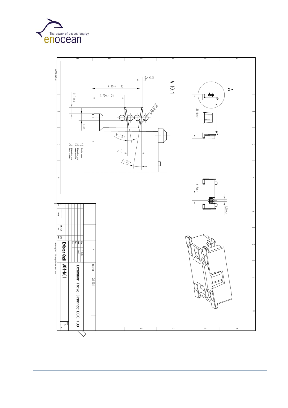
Figure 4: Definition of the rest positions and travel distance of the spring
©EnOcean GmbH, Dr. W. Heller
Page 9 of 10
ECO 100 User Manual V1.01

©EnOcean GmbH, Dr. W. Heller
Page 10 of 10
ECO 100 User Manual V1.01
Electrical characteristics:
Figure 5: Definition of polarity
Circuit used to characterise the Output Pulse:
=typ. 5V ±25%
U
10%UEND
90%UEND
time
T=rise time
UEND
Mechanical energy
ECO100
Electrical energy
+
- 19
µ
F UEND
Measurement
Equipment
(Ri = 10MΩ)
4x4,7µF
ceramic
capacitor
Rectifier
(diode bridge
2xBAT854SW)
Figure 6: Definition of the output pulse
Table of contents
Popular Media Converter manuals by other brands


Analog way
Analog way VIO 4K user manual

StarTech.com
StarTech.com 35SAT225S3R quick start guide

Absolute Process Instruments
Absolute Process Instruments IsoSplitter APD 4930 quick start guide

Extron electronics
Extron electronics MGP 641 Setup guide

Sonnet
Sonnet Qio CF4 Professional CompactFlash Media Reader &... user guide

Full Gauge
Full Gauge TCP-485 manual