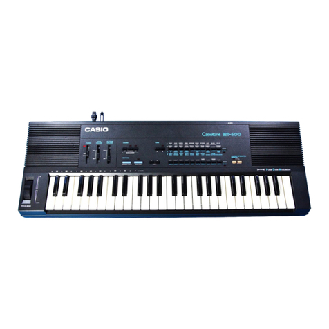
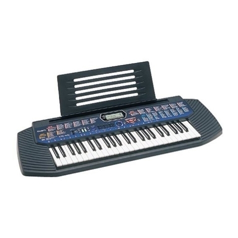
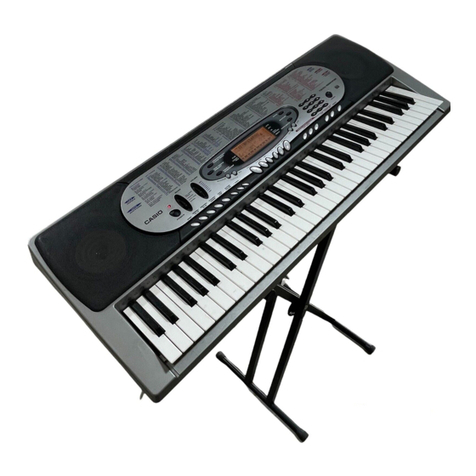
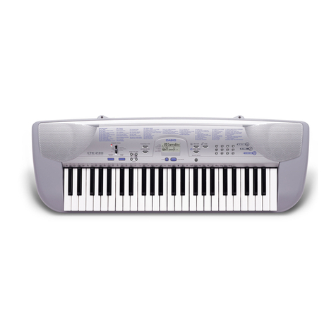
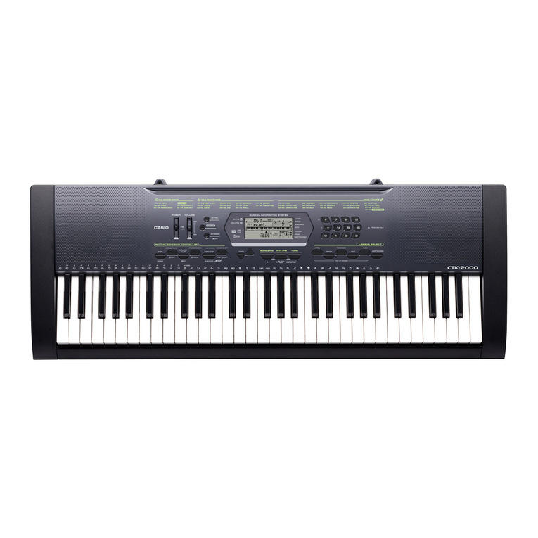
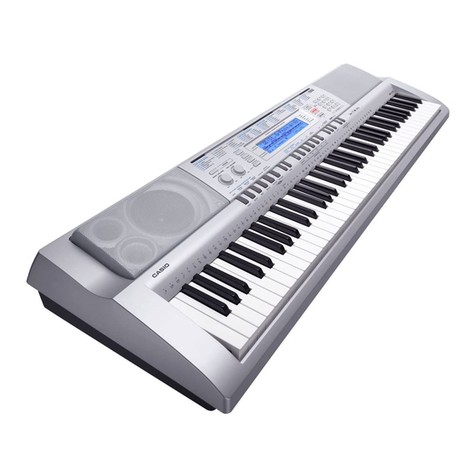
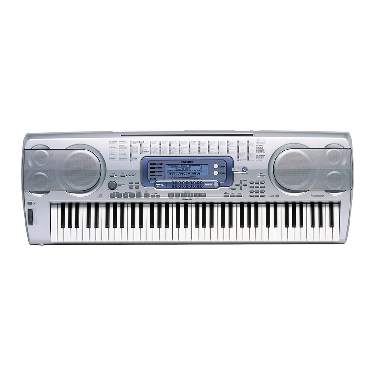
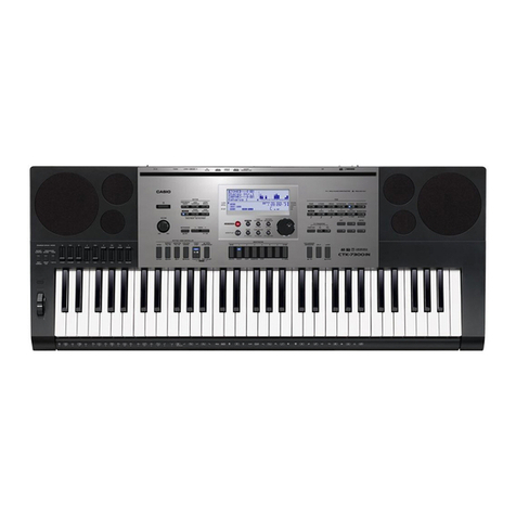
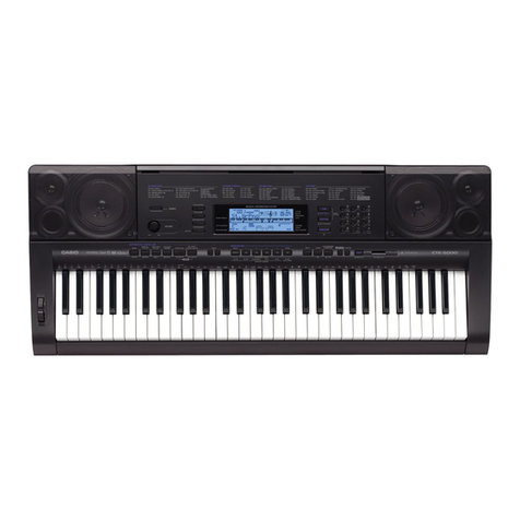
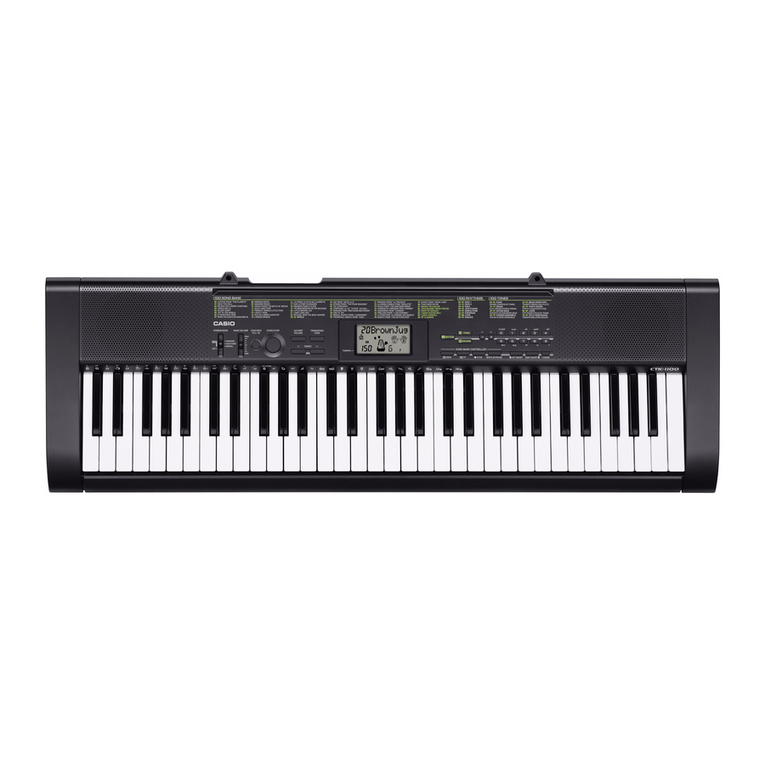
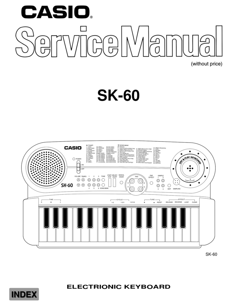
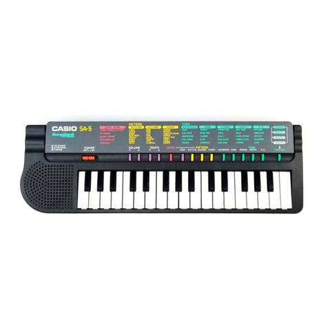
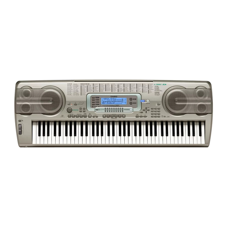
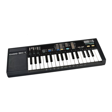
Casio CTK 591 - Full-Size 61 Key Keyboard User manual

— 1 —
SPECIFICATIONS
GENERAL
Keyboard: 61 standard-size keys, 5 octaves (with touch response on/off)
Tones: 255 (118 panel tones + 128 General MIDI tones + 9 drum sets); with layer
and split
Rhythm Instrument Tones: 61
Polyphony: 24 notes maximum (12 for certain tones)
Auto Accompaniment
Rhythm Patterns: 120
Tempo: Variable (216 steps, = 40 to 255)
Chords: 3fingeringmethods (CASIOCHORD, FINGERED,FULL RANGECHORD)
Rhythm Controller: START/STOP, INTRO, NORMAL/NORMAL FILL-IN, VARIATION/VARIA-
TION FILL-IN, SYNCHRO/ENDING
Accomp Volume: 0 to 127 (128 steps)
One Touch Presets: Recalls settings for tone, tempo, layer, split, and accompaniment volume
in accordance with rhythm.
<Advanced 3-Step Lesson System>
3-step Lesson: 3 lessons (Step 1, 2, 3)
Playback: Repeat play of a single tune
Evaluation Mode: Scoring 1, Scoring 2, Phrase Practice
Voice Fingering Guide: On/Off
Song Bank, Piano Bank
Number of Tunes: 100 (Song Bank/Sing Along: 50, Piano Bank: 50)
Controllers: PLAY/STOP, PAUSE, FF, REW, LEFT/RIGHT
Musical Information Function: Tone, Auto Accompaniment, Song Bank, Piano Bank, Sing Along numbers
and names; staff notation, tempo, metronome, measure and beat number,
step lesson display, chord name, fingering, pedal operation, Keyboard,
Song Bank icon, Piano Bank icon, Sing Along icon, Voice Fingering Guide,
Evaluation Mode
Sing Along Mode
Number of Tunes: Song Bank/Sing Along: 50
Controllers: PLAY/STOP, KEY CONTROL (25 steps, –12 semitones to +12 semitones)
Metronome: On/Off
Beat Specification: 1 to 6
Song Memory
Songs: 2
Recording Tracks: 2
Recording Method: Real-time
Memory Capacity: Approximately 5,100 notes (total for two songs)
MIDI: 16 multi-timbre receive, GM Level 1 standard
CONTENTS Page
Specifications ............................................................................................................................................ 1
Block Diagram........................................................................................................................................... 3
Circuit Description ..................................................................................................................................... 4
Adjustment ................................................................................................................................................ 5
Printed Circuit Boards ............................................................................................................................... 6
Disassemble/Assemble............................................................................................................................. 8
Diagnostic program ................................................................................................................................. 14
Schematic Diagrams ............................................................................................................................... 17
Exploded View ........................................................................................................................................ 22
Parts List ................................................................................................................................................. 23
— 2 —
Other Functions
Transpose: 25 steps (–12 semitones to +12 semitones)
Tuning: 101 steps (A4 = approximatery 440Hz ±50Cents)
Terminals
MIDI Terminals: IN, OUT
Assignable Jack: Standard jack (sustain, sostenuto, soft, rhythm start/stop)
Headphone/Output Terminal: Stereo standard jack
Output Impedance: 100Ω
Output Voltage: 4V (RMS) MAX
Microphone In: Standard jack (with microphone volume knob)
Input impedance: 3KΩ
Input sensitivity: 10mV
Power Jack: 9V DC
Power Supply: 2-way
Batteries: 6 D-size batteries
Battery Life: Approximately 6 hours continuous operation on manganese batteries
AC Adaptor: AD-5
Auto Power Off: Turns power off approximately 6 minutes after last key operation.
Enabled under batter power only, can be disabled manually.
Speaker Output: 2.5W + 2.5W
Power Consumption: 9V --- 7.7W
Dimensions: 96.0 ×37.5 ×14.5 cm (37 13/16 ×14 3/4×5 11/16 inch)
Weight: Approximately 5.3 kg (11.7 lbs)(without batteries)
About General MIDI
General MIDI standardizes MIDI data for all sound source types, regardless of manufacturer. General MIDI
specifies such factors as tone numbering, drum sounds, and available MIDI channels for all sound sources.
This standard makes it possible for all MIDI equipment to reproduce the same nuances when playing
General MIDI data, regardless of the manufacturer of the sound source.
This keyboard supports General MIDI, so it can be used to play commercially available pre-recorded
General MIDI data and General MIDI data send to it from a personal computer.
ELECTRICAL
Current drain with 9 V DC:
No sound output 175 mA ±20 %
Maximum volume 660 mA ±20 %
with 12 keys from C1 to G2 pressed in 104 SINE LEAD
Volume: maximum, Velocity: maximum
Speaker output level (Vrms with 4 Ωload each channel):
with key G1 in 104 SINE LEAD
Volume: maximun, Velocity: maximum L/R: 1400 mV ±20 %
Phone output level (Vrms with 32 Ωload each channel):
with key, G1 in 104 SINE LEAD
Volume: maximun, Velocity: maximum L/R: 293 mV ±20 %
Output level (Vrms with 47 Ωload each channel):
with key G1 in 104 SINE LEAD
Volume: maximun, Velocity: maximum L/R: 1350 mV ±20 %

— 3 —
BLOCK DIAGRAM
KC0 ~ KC7
FI0 ~ FI0
SI0 ~ SI7
MD0 ~ 5
LED0 ~
LED4
MWEB,
MCSB01,
MA18, 19
R/W, RS, DB4 ~ DB7, E
MIDI
Sound Source ROM
(32M-bit)
IC3
MR27V3202FSKMAZ020
D/A Converter
IC9
UPD6379LGR-E1
Filter
Q7 ~ Q10
Main
Volume
Power Amplifier
IC1
LA4598
Keyboard
MA0 ~ MA19
MCSB0
MCSB0, 1
MA18, 19
Power Supply Circuit
Q1 ~ Q6,
D1,D2,D4 ~ D7
(9V)
VC (5V)
VD5 (5V)
VA5 (5V)
VDP5
(9V)
VCP
APO
ADP Battery
APO Cancellation
L OUT
R OUT
Speakers
(L)
(R)
Phones/Output
LCD
LCD Driver
IC1
ML9040-B02GA
SEG1 ~ SEG40
IN
PED
OUT
Assingnable Jack
Reset IC
IC8
XC61FN2712MR
Chip Selector
IC5
TC74VHC153FT
RESET
COM1 ~ COM16
PG
X1
30MHz
MD0 ~ MD15
Buttons
VDP3Power Switch
NMI
LED
Driver
Q1 ~ Q6
CPU
IC7
GT915GF-3BA LED
LRCK
SO
BCK
5V 3V
Converter
MR27V3202PR
IC1
VDP5 VDP3
(5V)
Q11 D9
Mixer
IC2
NJM
14558D
MIC
MIC VR Amp.
IC1
NJM14558D
D3 AC Adaptor
DC 9V
Chip Selector
IC2, IC4, IC6
SN74AHCT08,
SN74LV20,
SN74LV174
(3V)

—4 —
CIRCUIT DESCRIPTION
KEY MATRIX
BUTTON MATRIX
F#3 G#3 A#3 C#4 D#4 F#4 G#4 A#4 C#5 D#5 F#5 G#5 A#5
F3 G3 A3 B3 C4 D4 E4 F4 G4 A4 B4 C5 D5 E5 F5 G5 A5 B5 C6
D#3
C2 D2 E2 F2 G2 A2 B2 C3 D3 E3 B6A6G6F6E6D6 C7
C#3A#2G#2
F#2D#2
C#2 A#6
G#6F#6D#6
C#6
KC0 KC1 KC2 KC3 KC4 KC5 KC6 KC7
KI0 SCORING STEP 2 3 TONE 5 PLAY/ SYNCHRO/
1 STOP FILL-IN
KI1 PRACTICE STEP 3 —76
KEY CONTROL KEY CONTROL
SING
PHRASE /TRANSPOSE /TRANSPOSE ALONG
KI2 STEP 1 0 + 4 MODE MODE MODE MODE
FULL RANGE
FINGERED CASIO NORMAL
CHORD CHORD
FI8 SCORING SPEAK METRO- INTRO NORMAL VAR START/STOP
2 NOME /FILL-IN /FILL-IN
FI9 LAYER RIGHT 2 RHYTHM 9 SONG OPEN TOUCH SETTING
/TRACK2 MEMORY PRESET
FI10 SPLIT LEFT 1SONG 8
TEMPO TEMPO PIANO
BANK
KC0 KC1 KC2 KC3 KC4 KC5 KC6 KC7-
C2 (1) C#2(1) D2 (1) D#2 (1) E2 (1) F2 (1) F#2 (1) G2 (1)
C2 (2) C#2 (2) D2 (2) D#2 (2) E2 (2) F2 (2) F#2 (2) G2 (2)
G#2 (1) A2 (1) A#2 (1) B2 (1) C3 (1) C#3 (1) D3 (1) D#3 (1)
G#2 (2) A2 (2) A#2 (2) B2 (2) C3 (2) C#3 (2) D3 (2) D#3 (2)
E3 (1) F3 (1) F#3 (1) G3 (1) G#3 (1) A3 (1) A#3 (1) B3 (1)
E3 (2) F3 (2) F#3 (2) G3 (2) G#3 (2) A3 (2) A#3 (2) B3 (2)
C4 (1) C#4 (1) D4 (1) D#4 (1) E4 (1) F4 (1) F#4 (1) G4 (1)
C4 (2) C#4 (2) D4 (2) D#4 (2) E4 (2) F4 (2) F#4 (2) G4 (2)
G#4 (1) A4 (1) A#4 (1) B4 (1) C5 (1) C#5 (1) D5 (1) D#5 (1)
G#4 (2) A4 (2) A#4 (2) B4 (2) C5 (2) C#5 (2) D5 (2) D#5 (2)
E5 (1) F5 (1) F#5 (1) G5 (1) G#5 (1) A5 (1) A#5 (1) B5 (1)
E5 (2) F5 (2) F#5 (2) G5 (2) G#5 (2) A5 (2) A#5 (2) B5 (2)
C6 (1) C#6 (1) D6 (1) D#6 (1) E6 (1) F6 (1) F#6 (1) G6 (1)
C6 (2) C#6 (2) D6 (2) D#6 (2) E6 (2) F6 (2) F#6 (2) G6 (2)
G#6 (1) A6 (1) A#6 (1) B6 (1) C7 (1)
G#6 (2) A6 (2) A#6 (2) B6 (2) C7 (2)
FI0
SI0
FI1
SI1
FI2
SI2
FI3
SI3
FI4
SI4
FI5
SI5
FI6
SI6
FI7
SI7
/TRACK1 BANK
NOMENCLATURE OF KEYS

— 5 —
3) Equipment connection/Procedure
Vop voltage setting
Watching the LCD at a 34.9°angle to the horizontal, adjust Vop
voltage so that unenergized segments are seen dimly.
ADJUSTMENT
DISPLAY PCB
1) Items to be adjusted:
2) Adjustment and Test Point Locations
(TOP VIEW)
Input
Connection Input
Point Input
Signal Adjust Output
Connection Output
Point Adjust for
VR1 Voltmeter VLCD-
VD5 Adjust for 4.2 ~ 4.3 V reading
on voltmeter under the tem-
perature 20 ~ 25 °C.
Makefineadjustmentaccord-
ing to the next instruction.
Output
Set Voltmeter
VLCD
VD5
34.9°
LCD
Eye
Item Measuring Instrument
Vop voltage setting Voltmeter
VLCD
VD5
30 pin
33 pin

— 6 —
PRINTED CIRCUIT BOARDS
Main PCB M704-MA1M
Top View
Top View
LCD PCB M704-LCD1M

— 7 —
Sub PCB JCM704-MA2M
Top View

— 8 —
DISASSEMBLY
1. Remove the battery cover and then the battery.
2. Remove 29 screws and then the upper case.
3. Remove 5 screws, 4 speaker cords, 1 power cord, 2 battery cords, 3 connectors (JH, JM, JN) and then the
PCB ASSY (MA2M).
Wire (Power switch)
Speaker cord (W)
Speaker cord (GR)
Speaker cord (BL)
Speaker cord (BR)
Battery cord (R)
Battery cord (B)
Screws
Connectors
Connector

— 9 —
4. Remove 4 screws, 6 connectors (JA, JB, JH, JJ, JK, JL) and then the PCB ASSY (MA1M).
6. Remove 2 screws and then the PCB ASSY (CN3M).
5. Remove 3 screws, 1 connector (JQ) and then the PCB ASSY (CN2M).
Screws
Connector
Screws
Screws
Connectors
Connectors
Connectors

— 10 —
7. Remove 2 screws, the volume slider, and then the PCB ASSY (CN4M).
8. Remove 6 screws and then the LCD ASSY (LCD1M).
Note: Tighten the screws in the order from 1 to 6 when reassembling.
Screws
Screws
Volume slider
12
3
4
5
6

— 11 —
9. Remove 28 screws and then the PCB ASSY (CN1M).
Note: Fix the LED (D4, D5, D50, D53, D54) to the PCB according to the height as shown in the figure below while
paying attention to the polarity.
Refer to the illustration on the PCB for the details of the polarity.
Anode
Cathode
8.7 ± 0.5 mm
D4,D54: 11.0 ±0.5 mm
D5: 11.5 ±0.5 mm
D53 D5 D54
D52 D4 D50 ■D50, D52, D53 ■D4, D54
■D5

— 12 —
10.Remove 13 screws and then the lower case.
11.Remove 19 screws and then the PCB ASSY (KY1M, KY2M).
12.Remove the rubber keys.
Note: Pay attention to the positions of the rubber keys as one of them has a different length.
Match the projections of the rubber keys with the holes of the lower case when reassembling.
Note: Tighten the screw with the arrow mark in the figure first when reassembling.
Cushion
Projection

— 13 —
13.Remove 21 screws and then the white keys.
14.Remove the black keys.
Note: Pay attention to the positions of the screw holes when
reassembling.

— 14 —
DIAGNOSTIC PROGRAM
■Initial Setup
a. Connect an AC cord.
b. Connect a Pedal cord.
c. "MODE" switch: NORMAL
d. "Main" volume: MAX
e. Connect a MIDI cable (In-Out).
Note: If there is no pedal or MIDI cable, pedal or MIDI check can be skipped.
■How to start diagnostic program
a. While pressing “0” button, turn “POWER” switch ON.
b. Confirm “00” message on top of LCD.
c. If everything is OK, release “0” buttons.
d. As for the details of each diagnostic procedure, refer to the attached sheets.
NOTE:
Refer to the figure below for the LCD messages that appear during the diagnostic program.
DP3

— 15 —
■Diagnostic program
Message on LCD
1. Console check
1Press "0" button to enter "Console check". DP3: 00
*Confirmation sound sounds.
2Press buttons in the order from No.1 to No2C. DP3: BUTTON NO.
NOTE: The button numbers are written in hexadecimal numerals.
Press the "SPLIT" button the last. DP3: COK
* Confirmation sound sounds.
* The Button number appears on the LCD (DP3). DP3: BUTTON NO.
*
A buzzer sounds if buttons are pressed in a wrong order, and "CER" appears on LCD (DP3).
DP3: CER
NOTE: This check cannot be aborted in mid-course.
01
2
3
4 5 6
8
79
0
B
0
C
0
D
0
E
0
F
10 11
12 13 14 15 16
17 18 19
20
21
22
23

27
26
25
24
28
29
2
A
2
B
2
C
COK
1
B
1
C
1
D
1
E
1
F
1
A
0A
Message on LCD
2. AC adaptor check
1Press "–" button to enter "AC adaptor check". DP3: JOK
3. Pedal check (If no pedal, this check can be skipped)
1Press "1" button to enter "Pedal check". DP3: TCH
2Step on the "SUSTAIN" PEDAL. DP3: SUS
3Release the "SUSTAIN" PEDAL.
4. ROM check
1Press "2" button to enter "ROM check". DP3: 111
* Confirmation sound sounds. DP3: OOK

— 16 —
Message on LCD
5. Sound check
1Press the "4" button to enter "Sound check". DP3: MIN
*When standing in the center, the judge hears the minimum test sound in an equal volume
from both right and left speakers.
2Press the "5" button. DP3: MID
*When standing in the center, the judge hears the medium test sound in an equal volume
from both right and left speakers.
3Press the "6" button. DP3: MAX
*When standing in the center, the judge hears the maximum test sound in an equal vol-
ume from both right and left speakers.
4Press the "7" button. DP3: L
*When standing in the center, the judge hears the maximum test sound fromthe left speaker.
5Press the "8" button. DP3: R
* When standing in the center, the judge hears the maximum test sound from the right speaker.
6. MIDI check (If there is no MIDI cable, this check can be skipped)
1Press "9" button to enter "MIDI check". DP3: DOK
7. LCD check
1Press the "STEP1" button to enter "LCD check".
*All dots and characters of LCD turn on.
* There is no lack of the dot and the charater.
8. Corsor LED check
1Press the "SPEAK" button to enter "Corsor LED".
* Keyboard LED must light in the undermentioned order.
1) PIANO BANK + RHYHTM CONTROLLER
2) SONG BANK + RHYHTM CONTROLLER
3) SING ALONG + RHYHTM CONTROLLER
4) SONG/PIANO BANK CONTROLLER
5) RHYHTM CONTROLLER
9. APO check
1Press the "PRACTICE PHRASE" button.
* Go out from TEST mode (Power off).
* The LCD turns off.
DIAGNOSTIC PROGRAM IS FINISHED.

— 17 —
SCHEMATIC DIAGRAMS
Main PCB M704-MA1M

— 18 —
Sub PCB M704-MA2M

— 19 —
Console PCB M704-CN1M/CN4M/CN5M/CN6M/CN7M
Other manuals for CTK 591 - Full-Size 61 Key Keyboard
1
Table of contents
Other Casio Electronic Keyboard manuals

Casio
Casio ToneBank CT-670 User manual

Casio
Casio LK-50 Service manual

Casio
Casio LK-50 User manual

Casio
Casio CTK-4000 Technical document

Casio
Casio SA-46 User manual

Casio
Casio CTK-900 User manual

Casio
Casio WK-3800 User manual

Casio
Casio WK-1600 User manual

Casio
Casio CTK-4200 User manual

Casio
Casio LK-50 User manual

Casio
Casio Privia PX-410R Technical document

Casio
Casio CTK-496 User manual

Casio
Casio CTK-573 User manual

Casio
Casio MZ-2000 User manual

Casio
Casio LK-50 User manual

Casio
Casio CTK-245 User manual

Casio
Casio CTK-691 User manual

Casio
Casio TONEBANK CT-390 User manual

Casio
Casio WK-1500 User manual

Casio
Casio WK-1800 User manual