Casio LK-300TV User manual

ELECTRONIC KEYBOARD
LK-300TV
MAY. 2006
LK-300TV
INDEX

CONTENTS
Specifications ---------------------------------------------------------------------------------------------- 1
Circuit Description --------------------------------------------------------------------------------------- 2
Printed Circuit Board ------------------------------------------------------------------------------------ 3
Diagnostic Program -------------------------------------------------------------------------------------- 6
Exploded View --------------------------------------------------------------------------------------------- 9
Parts List--------------------------------------------------------------------------------------------------- 10
Schematic Diagrams ----------------------------------------------------------------------------------- 13

— 1 —
SPECIFICATIONS
GENERAL
Keyboard: 61 standard-size keys, 5 octaves (with touch response; 1, 2, off)
Key Light System: Can be turned on and off (up to 10 keys can be lit at the same time)
Tones: 514 (372 panel tones + 128 General MIDI tones + 14 drum sets); with layer and split
Digital Effects: Reverb (4 types), Chorus (4 types)
Polyphony: 32 notes maximum (16 for certain tones)
Auto Accompaniment
Rhythm Patterns: 120
Chords: 3 fingering methods (CASIO CHORD, FINGERED, FULL RANGE CHORD)
Rhythm Controller: START/STOP, INTRO, NORMAL/FILL-IN, VARIATION/FILL-IN,
SYNCHRO/ENDING
Accomp Volume: 0 to 127 (128 steps)
<Advanced 3-Step Lesson System>
3-step Lesson: 3 lessons (Step 1, 2, 3)
Playback: Repeat play of a single tune
Lesson Part: Left hand, right hand, both hands
Evaluation Mode: Scoring 1, Scoring 2, Scoring 3, Phrase Practice
Voice Fingering Guide: On/Off
Song Bank, Piano Bank
Number of Tunes: 100 (Song Bank/Karaoke: 50, Piano Bank: 50)
Controllers: PLAY/STOP, PAUSE, FF, REW, REPEAT
User Songs: Number of Songs: Up to 10 download songs
Capacity: Approximately 320 KB∗
∗Calculated based on 1 KB = 1024 bytes.
Karaoke Mode
Number of Tunes: Song Bank/Karaoke: 50
Controllers: PLAY/STOP, PAUSE, FF, REW, REPEAT, KEY CONTROL (25 steps, –12 semitones
to +12 semitones)
Metronome: On/Off
Beat Specification: 0, 2 to 6
Song Memory
Number of Songs: Two (1 Lesson Recording, 1 Performance Recording)
Recorded Data: Lesson Recording: Right-hand part, left-hand part, both-hand parts
Performance Recording: Track 1 (chord accompaniment), Track 2 (melody)
Recording Method: Real-time
Memory Capacity: Approximately 5,200 notes (two songs)
Other Functions
Tempo: Variable (226 steps, = 30 to 255)
Transpose: 25 steps (–12 semitones to +12 semitones)
Tuning: 101 steps (A4 = approximatery 440Hz ±50Cents)
Card
Supported Memory Cards: SD memory cards, optional CASIO song data cards∗
∗May not be available in some geographic areas.
Supported SD Cards: 1 GB or less (Cards with capacity greater than 1 GB are not supported.)
Maximum Number of
Importable Songs: Up to 1,000
Supported Data: SMF Format 0, CASIO Original Format CM2

— 2 —
SWO0
SWO1
SWO2
SWO3
SWO4
SWO5
SWI4
5
6
8
INTRO
9
PIANO
BANK
SWI5
PLAY/
STOP
KEY
DOWN
SYNCRO/
FILL-IN
START/
STOP
REVERB/
CHORUS
LEFT
SWI2
3
0
+
SCORING3
2
1
SWI3
TONE
7
4
METRONOME
RHYTHM
SONG
BANK
SWI0
SCORING1
PRACTICE
PHRASE
STEP1
SCORING2
LAYER
RIGHT/
TRACK2
SWI1
STEP2
STEP3
–
SPEAK
SPRIT
LEFT/
TRACK1
BUTTON MATRIX
CIRCUIT DESCRIPTION
KEY MATRIX
KC0 KC1 KC2 KC3 KC4 KC5 KC6 KC7-
C2 (1) C#2(1) D2 (1) D#2 (1) E2 (1) F2 (1) F#2 (1) G2 (1)
C2 (2) C#2 (2) D2 (2) D#2 (2) E2 (2) F2 (2) F#2 (2) G2 (2)
G#2 (1) A2 (1) A#2 (1) B2 (1) C3 (1) C#3 (1) D3 (1) D#3 (1)
G#2 (2) A2 (2) A#2 (2) B2 (2) C3 (2) C#3 (2) D3 (2) D#3 (2)
E3 (1) F3 (1) F#3 (1) G3 (1) G#3 (1) A3 (1) A#3 (1) B3 (1)
E3 (2) F3 (2) F#3 (2) G3 (2) G#3 (2) A3 (2) A#3 (2) B3 (2)
C4 (1) C#4 (1) D4 (1) D#4 (1) E4 (1) F4 (1) F#4 (1) G4 (1)
C4 (2) C#4 (2) D4 (2) D#4 (2) E4 (2) F4 (2) F#4 (2) G4 (2)
G#4 (1) A4 (1) A#4 (1) B4 (1) C5 (1) C#5 (1) D5 (1) D#5 (1)
G#4 (2) A4 (2) A#4 (2) B4 (2) C5 (2) C#5 (2) D5 (2) D#5 (2)
E5 (1) F5 (1) F#5 (1) G5 (1) G#5 (1) A5 (1) A#5 (1) B5 (1)
E5 (2) F5 (2) F#5 (2) G5 (2) G#5 (2) A5 (2) A#5 (2) B5 (2)
C6 (1) C#6 (1) D6 (1) D#6 (1) E6 (1) F6 (1) F#6 (1) G6 (1)
C6 (2) C#6 (2) D6 (2) D#6 (2) E6 (2) F6 (2) F#6 (2) G6 (2)
G#6 (1) A6 (1) A#6 (1) B6 (1) C7 (1)
G#6 (2) A6 (2) A#6 (2) B6 (2) C7 (2)
FI0
SI0
FI1
SI1
FI2
SI2
FI3
SI3
FI4
SI4
FI5
SI5
FI6
SI6
FI7
SI7
C2 C3 C4 C5 C6 C7
NOMENCLATURE OF KEYS
SWI6
SONG
MEMORY
KEY UP
SETTING
KEY LIGHT
RIGHT
SWI7
SYNCRO/
FILL-IN
KARAOKE

— 3 —
PRINTED CIRCUIT BOARDS
Main PCB M664-MDA1

— 4 —
CONSOLE PCB M664-CNA1
CONSOLE PCB M664-CNA2 CONSOLE PCB M664-CNA3 CONSOLE PCB M664-CNA4

— 5 —
SUB PCBs M664-SDA1
LED PCBs CSM446-LD3M/LD4M/LD5M

— 6—
DIAGNOSTIC PROGRAM
■ Initial Setup
1. Connect the AC adaptor.
2. Connect a Sustain pedal.
3. Setting SD card into slot.
3. “MODE” switch: NORMAL
4. “MAIN VOLUME”: MAX
5. “MIC VOLUME”: MIN
NOTE: If there is no Sustain pedal, Sustain pedal check can be skipped.
■ How to start diagnostic program
1. Press and hold the “0” and “9” buttons.
2. Press the “POWER” button.
3. The massage “TST” is appears on LCD.
4. Release the “0” and “9” buttons.
■ Diagnostic program
1. SWITCH check
1Press “0” button.
* Wait for confirmation sound.
2Slide switches or press buttons in the order from No.01 to No.49.
* Confirmation sound sounds.
* The Button number appears on the LCD.
* A buzzer sounds if buttons are pressed in a wrong order, and “NG” appears on LCD.
NOTE: The button numbers are written in hexadecimal numerals.
3Press the “LAYER” button the last.
* Wait for confirmation sound.
* The massage “COK” is appears on LCD.
NOTE: This check cannot be aborted in mid-course.
2. AC adaptor check
1Press “–” button.
3. Pedal check
1Press “1” button.
2“Sustain pedal”: ON
3“Sustain pedal”: OFF
4. ROM check
1Press “2” button.
* Confirmation sound sounds.
5. MODEL check
1Press “3” button.
Message on LCD
JOK
TCH
SUS
OOK
664
]^g
a\ f
b[ e
cZ
YX
W
V U T
PQRS
d
1
ONMLKJHGFEDC
BA
09
87
6
5
4
3
2h i

— 7—
6. ROM Ver. check
1Press “3” button. (internal ROM)
2Press “3” button. (extenal ROM)
7. RAM check
1Press “+” button.
* Confirmation sound sounds.
8. D/A check
1Press the “4” button.
* When standing in the center, the tester hears the minimum test sound in an
equal volume from both right and left speakers.
2Press the “5” button.
* When standing in the center, the tester hears the medium test sound in an
equal volume from both right and left speakers.
3Press the “6” button.
* When standing in the center, the tester hears the maximum test sound in an
equal volume from both right and left speakers.
4Press the “7” button.
* When standing in the center, the tester hears the maximum test sound from
the left speaker.
5Press the “8” button.
* When standing in the center, the tester hears the maximum test sound from
the right speaker.
9. SD check
1Press the “CARD” button.
* Confirmation sound sounds.
NOTE: If “CARD” button at lock mode, “PT UER” is appears on LCD.
10. LCD check
1Press the “STEP1” button.
* All dots and characters of LCD turn on.
* There is no lack of the dot and the charater.
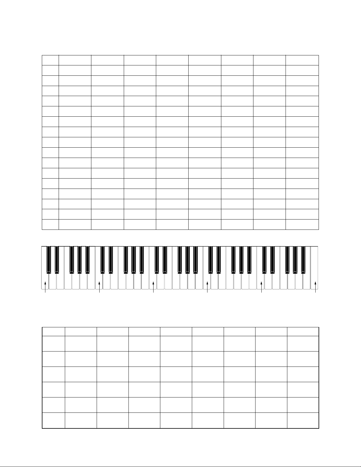
11. KEY LED check
1Press “SCORING1” button.
* The key lights with confirmation sound in the following order.
* There must not be remarkable difference in the LED brightness of the
adjacent key.
Message on LCD
200
200
AOK
MIN
MID
MAX
L
R
UOK
1) C1, D1, E1, F1, G1, A1, B1
2) C2, D2, E2, F2, G2, A2, B2
3) C3, D3, E3, F3, G3, A3, B3
4) C4, D4, E4, F4, G4, A4, B4
5) C5, D5, E5, F5, G5, A5, B5, C6
6) C1#, D1#, E1#, F1#, G1#, A1#
7) C2#, D2#, E2#, F2#, G2#, A2#
8) C3#, D3#, E3#, F3#, G3#, A3#
9) C4#, D4#, E4#, F4#, G4#, A4#
10) C5#, D5#, E5#, F5#, G5#, A5#
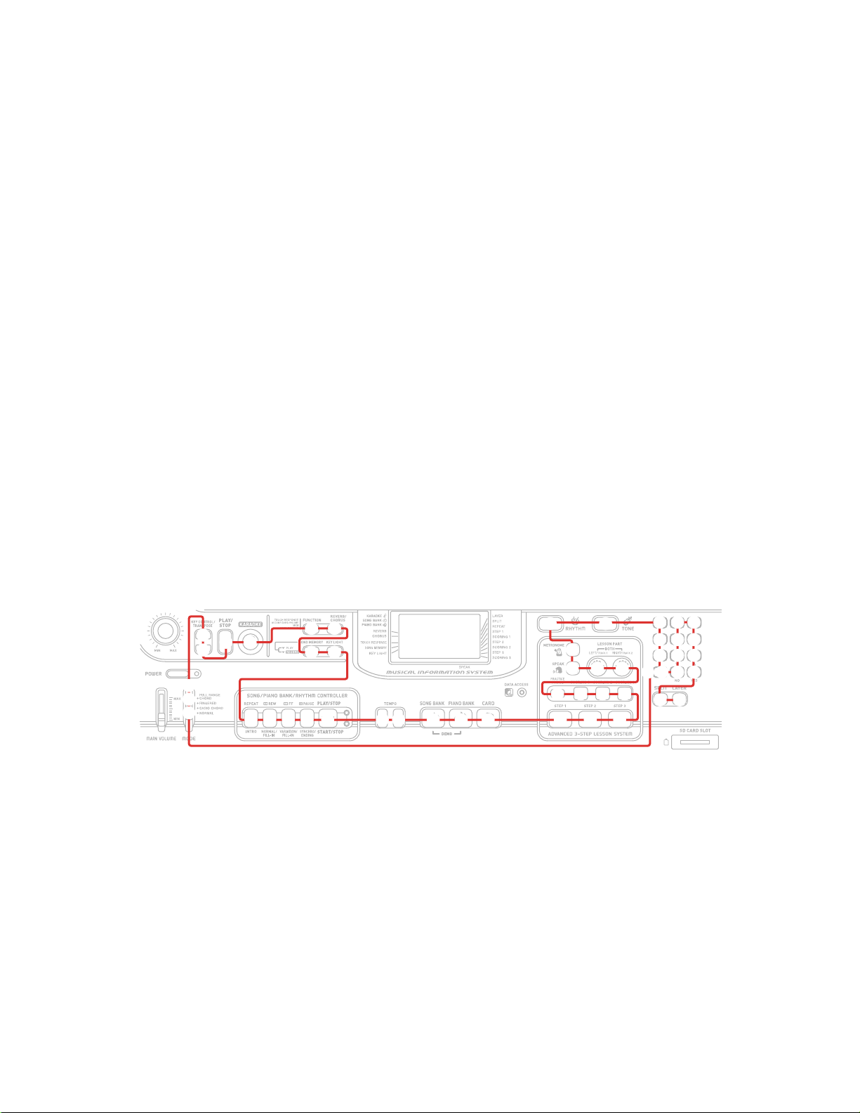
11. Console LED check
1Press the “SPEAK” button.
* Keyboard LED must light in the undermentioned order.
1) DATA ACCESS
2) SONG CONTROLLER
3) RHYTHM CONTROLLER

— 8—
Message on LCD
To discharge
12. APO check
1Press the “PRACTICE PHRASE” button.
* Go out from TEST mode (Power off).
* The LCD turns off.
* Disconnect an AC adaptor.
* Disconnect the SD card from slot.
* Press the “POWER” button 3 times
DIAGNOSTIC PROGRAM IS FINISHED.

— 9 —
EXPLODED VIEW
26
22
35
6
7
37
36
20
21
18
19
34
31
30
38
17
16
15
33
13
14
39
26
8
9
11
12
10
1
2
3
R-3
R-4
1-1
R-2
R-1
23
32
29
27
28
45
25
24

—10 —
Notes: This parts list does not include the cosmetic parts,
which parts are marked with item No. "R-X" in the
exploded view.
Contact our spare parts department if you need
these parts for refurbish.
1. Prices and specifications are subject to change
without prior notice.
2. As for spare parts order and supply, refer to the
"GUIDEBOOK for Spare parts Supply",
published seperately.
3. The numbers in item column correspond to the
same numbers in drawing.
PARTS LIST
LK-300TV

N Item Parts Code Parts Name Specification QTY Price
Code R Remarks
Main PCB
N 1 10243438 PCB ASSY/MAIN TK-RJM506904*001 1 DI A NTSC
N 1 10243444 PCB ASSY/MAIN TK-RJM506904*002 1 DI A PAL
D1,2,3 23901820 DIODE 1SS355TE-17 3 AD X
IC7,8 10116986 I.C SN74AHCT1G08DCKR 2 AA C
NIC22 10240648 IC TC74LCX08FT(EL.K) 1 AH C
IC14 10197553 IC TC7S04FU(TE85L.F) 1 AE C
IC17 10197554 IC TC7SZ126FU(TE85L.F 1 AE C
IC16,23 10197555 IC TC7SZ14FU(TE85L.F) 2 AE C
IC5 10197809 IC TC7WH123FU(TE12L.
F
1BOC
IC21 10187219 LSI SPG200A-C 1 AJ C
NIC19 10184585 LSI CY62146DV30LL55ZS
X
1CGC
L6 10171010 COIL LQM18NN1R8K00D 1 AC X
Q5 10153685 FET 2SJ346(TE85L.F) 1 AA X
Q1 10015566 TRANSISTOR 2SB1181TLR 1 AC C
Q2,3,20 10202670 TRANSISTOR KTA2014-GR-RTK/P 3 AA C
Q6,Q10-13 10209018 TRANSISTOR KTA501U-GR-RTK/P 5 AC C
X3 10096483 CERAMIC OSCILLATO
R
CSBFB1M00J58-R1 1 AG C
NX2 10240828 RESONATOR SSL6000000F16F5FZ8 1 AA C
X1 10211946 RESONATOR SSM1200000F17F5FZ
8
1ACC
L7 10158809 COIL DLP31SN221SL2L 1 AI X
J1 10171003 CONNECTOR JY-3545B*01-130 1AFX
N 1-1 10243446 PCB ASSY/SDA1 TK-RJM506910*001 1AAC
Console unit
N 2 10243435 PCB ASSY/CNA1 TK-RJM506895*001 1 BV C
IC2 10190010 IC LA4598-E 1 AG C
IC1,3 10206677 IC NJM2068D-D 2AA
C
NQ4 10206835 TRANSISTOR KTA1046-Y-U/P 1AA
C
Q6 10206676 TRANSISTOR KTC2026-Y-U/P 1AH
C
VR3 69304870 SEMI FIXED VOL EVND8AA03B53 1AA
X
D3 10079928 DIODE 1SS133TA 1AA
X
D2 10079931 DIODE DZ5.1BSCTA 1AA
X
D7 10085189 ZENER DIODE DZ5.6BSBTA 1AA
X
ND9 10206836 LED 1154HD-B5/5.5-90 1AA
X
D8 10106131 LED 1154HD-B5/6-90 1AA
X
D12 10116453 LED 1154HD-B5/6.5-90 1AB
X
D1 10107268 LED 1154HD-B5/7-90 1AA
X
NQ2 10206675 TRANSISTOR KTA1273-Y-AT/P 1AB
C
Q1,3,5 10206673 TRANSISTOR KTC3199-GR-AT/P 3AA
C
N 3 10243445 PCB ASSY/CNA2 TK-RJM506907*001 1 AW C
J3 10088189 DC JACK DS-240A2-383V4H 1 AA C DC JACK
J4 10206815 CONNECTOR JY-6314*01-030 1 AA X
J1 10206816 CONNECTOR JY-6314*01-130 1 AE X
J2 10213695 JACK JY-6316*01-070 1 AY C PHONE JACK
NL2 10231919 COIL RB53-856396NP 1 AA X
NL1,3,4 10231920 COIL RB53-856397NP 3 AA X
N 4 10243436 PCB ASSY/CNA3 TK-RJM506898*001 1 AR C
VR2 27652213 VARIABLE R RS20H121-2KB 1ASX
N 5 10243437 PCB ASSY/CNA4 TK-RJM506901*001 1 AQ C
VR1 10122622 VARIABLE R RK09D1130C49 1AEX
6 10197541 REFLECTOR RJM505356-001V01 1 AA C
N 7 10243431 BL ASSY TK-RJM505339*002 1 BT C
Notes : Q - Quantity per unit
R - Rank
―11 ―

N Item Parts Code Parts Name Specification QTY Price
Code R Remarks
Key board assy
810200656 PCB ASSY/LDA1 TK-RJM505754*001 1 BU C
D501-515 23701408 LED SLI-332URCTJ2 15 AA C
910200657 PCB ASSY/LDB2 TK-RJM505756*001 1 BJ C
D516-536 23701408 LED SLI-332URCTJ2 21 AA C
10 10037820 PCB ASSY/LD3M TK-M240428*6(M476) 1 AS C
11 10037819 PCB ASSY/LD4M TK-M240429*6(M476) 1 AS C
12 10037818 PCB ASSY/LD5M TK-M240430*6(M476) 1 AT C
13 10135908 PCB ASSY/LDA TK-RJM503255*001 1 AR C
N14 10243426 PCB ASSY/KY1M TK-M140687*013 1 AX C
N15 10243427 PCB ASSY/KY2M TK-M140688*014 1 AW C
16 69222772 RUBBER/CONTACT/CS M211705B-1 1 AD B
17 69222762 RUBBER/CONTACT/CB M211704B-1 4 AF B
18 10008322 KEY SET/5P BLACK M140369C-2 1 AM C
19 10079624 KEY SET/10P BLACK M140369D-1 2 BN C
20 10014609 KEY SET/WHITE/CS M340489A*4 1 AV C
21 10014608 KEY SET/WHITE/CB M340489A*3 4 AU C
Case unit
N22 10240808 PLATE/DISPLAY RJM505352-002V01 1 AA C
N23 10240831 KNOB/ROTARY RJM502503-001V02 1 AC C
N24 10240416 KNOB/SLIDE RJM503803-004V01 2 AE C
25 69270510 CONTACT/SLIDE CSB-08D 1 AA C
N26 10228225 SPEAKER C12JA17 2 AA C
N27 10240832 RUBBER/KEY/A RJM505342-002V01 1 AE C
N28 10240834 RUBBER/KEY/B RJM505343-002V01 1 AB C
N29 10240835 RUBBER/KEY/C RJM505344-002V01 1 AD C
N30 10240836 RUBBER/KEY/D RJM505345-002V01 1 AC C
N31 10240833 RUBBER/KEY/A RJM506545-001V01 1 AA C
N32 10240837 RUBBER/KEY/F RJM505347-002V01 1 AC C
N33 10240838 RUBBER/KEY/G RJM505348-002V01 1 AF C
N34 10240839 RUBBER/KEY/H RJM505349-002V01 1 AE C
N35 10240840 RUBBER/KEY/J RJM505350-002V01 1 AA C
N36 10240841 RUBBER/KEY/K RJM505351-002V01 1 AA C
37 10171015 LCD TR3690N 1 AU C
38 10197537 CONNECTOR RJM505353-001V01 1 AF C
39 10200658 COVER/BATTERY TK-M341235*008 1 DB B
Accessory
N - 10240825 LABEL/RATING M341007-059V01 1 AA X NTSC
N - 10240826 LABEL/RATING M341007-061V01 1 AG X PAL
- 10055632 BATTERY GP13A0-9S2 3 BH C
- 10131421 MIC DM-302-2 1 BJ C Except US
- 10171020 VIDEO CABLE CA-8101-300-A08 1 AQ C
N - 10236617 CD ROM USB12CDROMWL1C 1 AA C
- 10118186 STAND/SCORE M311760-001V02 1 AK C
Refurbish
N R-1 10243432 CASE ASSY/UPPER TK-RJM506553*001 1 CF C
R-2 10200661 CASE ASSY/MIDDLE TK-M141274*016 1 CD C
R-3 10200662 CASE ASSY/FK TK-M341357*007 1 AA C
R-4 69069252 PLATE/LOWER M240573B-2 1 AF C
Notes : Q - Quantity per unit
R - Rank
―12 ―

— 13 —
SCHEMATIC DIAGRAMS
MAIN PCB M664-MDA1(1/2)

— 14 —
MAIN PCB M664-MDA1(2/2)

— 15 —
CONSOLE PCB M664-CNA1

— 16 —
CONSOLE PCBs M664-CNA2/CNA3/CNA4

— 17 —
KEY LED PCB M655-LDA1

— 18 —
KEY LED PCB M655-LDB2
Other manuals for LK-300TV
1
Table of contents
Other Casio Electronic Keyboard manuals

Casio
Casio Oriental Maestro AT1 User manual

Casio
Casio CTK-731 User manual

Casio
Casio CTK-900 User manual

Casio
Casio SA-65 User manual

Casio
Casio CTK-531 User manual

Casio
Casio WK-3800 User manual

Casio
Casio MZ-X500 User manual

Casio
Casio SK-60 User manual

Casio
Casio WK-3000 User manual

Casio
Casio Privia PX-330BK Troubleshooting guide

Casio
Casio Cosmo CZ-1 Guide

Casio
Casio CTK-530 User manual

Casio
Casio CTK-40I User manual

Casio
Casio SA-76 User manual

Casio
Casio ToneBank MA-101 User manual

Casio
Casio CTK-2000 User manual

Casio
Casio Celviano AP-21 User manual

Casio
Casio LK-50 Instruction manual

Casio
Casio CTK-480 User manual

Casio
Casio CTK-573 User manual