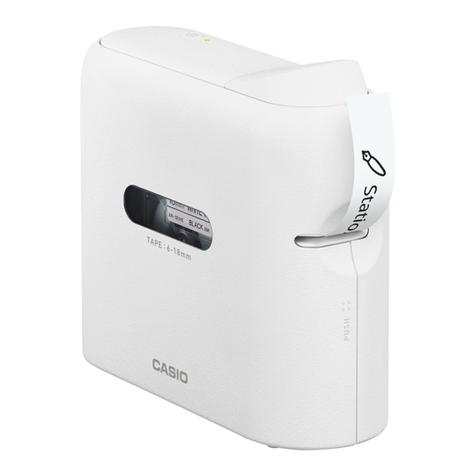
Casio QG-100 Troubleshooting guide

JULY 1996
(without price)
QG-100
(ZX-568)

CONTENTS
1. SPECIFICATIONS ..................................................................................................................... 1
2. CLEANING THE PRINTER........................................................................................................1
3. BLOCK DIAGRAM .................................................................................................................... 2
4. SCHEMATIC DIAGRAMS
4-1. Wiring Diagram.................................................................................................................. 3
4-2. Main PCB Z568-1 (1/2).......................................................................................................4
4-3. Main PCB Z568-1 (2/2).......................................................................................................5
4-4. Power PCB Z568-S1 ..........................................................................................................6
4-5. Sensor PCB Z568-2 ...........................................................................................................7
4-6. Cam sensor PCB Z568-S2 ................................................................................................8
4-7. Paper, Ribbon & Jam sensor PCB Z568-S3 ....................................................................8
4-8. Key Matrix Z568-E4 ...........................................................................................................8
5. CIRCUIT EXPLANATION
5-1. LSI PIN FUNCTION ............................................................................................................9
5-2. CIRCUIT EXPLANATION ................................................................................................. 11
6. SETTING THE THERMAL HEAD ............................................................................................12
7. SENSOR POSITION, PRINTING SPECIFICATION & OPERATION CHECK ........................ 14
7-1. SENSOR POSITION ......................................................................................................... 15
7-2. PRINTING SPECIFICATION.............................................................................................15
7-3. OPERATION CHECK .......................................................................................................17
8. TROUBLE SHOOTING............................................................................................................ 21
9. DISASSEMBLY........................................................................................................................ 25
10. PARTS LIST
10-1. Z568-1 ASS'Y, COMPONENTS & OTHERS...................................................................27
10-2. PRINTER UNIT ............................................................................................................... 31
10-3. CHASSIS UNIT............................................................................................................... 34
10-4. CHASSIS ASS'Y............................................................................................................. 37
10-5. HEAD HOLDER ASS'Y ..................................................................................................40
10-6. PLATEN ASS'Y .............................................................................................................. 43
10-7. CASSETTE CASE ASS'Y...............................................................................................45
10-8. MOTOR CHASSIS ASS'Y ..............................................................................................47
11. EXPLODED VIEW & DISASSEMBLY VIEW
11-1. EXPLODED VIEW (Z568-1 ASS'Y & COMPONENTS) ................................................. 30
11-2. DISASSEMBLY VIEW (PRINTER UNIT) ........................................................................32
11-3. DISASSEMBLY VIEW (CHASSIS UNIT)........................................................................35
11-4. DISASSEMBLY VIEW (CHASSIS ASS'Y)......................................................................38
11-5. DISASSEMBLY VIEW (HEAD HOLDER ASS'Y)............................................................41
11-6. DISASSEMBLY VIEW (PLATEN ASS'Y)........................................................................44
11-7. DISASSEMBLY VIEW (CASSETTE CASE ASS'Y)........................................................46
11-8. DISASSEMBLY VIEW (MOTOR CHASSIS ASS'Y)........................................................48

— 1 —
1. SPECIFICATIONS
Model: QG-100
Print System: Thermal transfer
Power Consumption: 20 W
Auto Power Off: Approximately 30 minutes after last operation
Operating Temperature: 10 °C to 35 °C (50 °F ~ 95 °F)
Dimensions: 96.5 (H) ×154 (W) ×154 (D) mm (313/16"H ×61/16 "W ×61/16"D)
Weight: 980 g (2.2 lbs)
Current: DC 890 mA (TYP.), DC 1200 mA (MAX.) (printing)/DC 87 mA (TYP.),
DC 132 mA (MAX.) (power off)
2. CLEANING THE PRINTER
For best printing results, use the following procedure to clean the print head and rollers with alcohol.
Also note that tape adhesive tends to accumulate on the sides of the tape outlet after long use of the
QG-100. When this happens, use an alcohol-moistened cotton swab to clean off the adhesive.
1Open the printer’s cover.
2Use a thin cotton swab (the kind designed for infants)
moistened with alcohol to lightly wipe the printer head
as shown in the illustration.
3Thoroughly wipe off the rubber rollers with the cotton
swab.
Important!
• The print head and other nearby metal parts become quite hot after the printer is used for a long time.
Make sure you allow these components to cool sufficiently before cleaning.

— 2 —
3. BLOCK DIAGRAM

— 3 —
4. SCHEMATIC DIAGRAMS
4-1. Wiring Diagram

— 4 —
4-2. Main PCB Z568-1 (1/2)

— 5 —
4-3. Main PCB Z568-1(2/2)

— 6 —
4-4. Power PCB Z568-S1

— 7 —
4-5. Sensor PCB Z568-2
6 mm 9 mm 12 mm 18 mm 18 mm (R) 24 mm 36 mm 46 mm no tape Z568 (PORT-PCU)
Tape width TAP1: ON ON ON ON OFF OFF OFF OFF OFF P74 (89P)
ON = L TAP2: OFF OFF ON ON ON ON ON OFF OFF P75 (90P)
TAP3: OFF ON OFF ON OFF ON OFF ON OFF P76 (91P)
Tape (mono/color) TAP4: MONO →L COLOR →H P70 (85P)
Tape length TAP5: Short →H Long →L P71 (86P)
Ink ribbon position TAP7: White →L Black →H KI6 (83P)
Paper position TAP8: White →L Black →H KI5 (82P)
Starting position TAP9: Home position L Platen down L After cutting tape H KI4 (81P)
TAP10: H L L KI3 (80P)
JAM TAP11: jam →L not jam →H KI7 (84P)

— 8 —
4-7.(2/2) Jam sensor PCB Z568-S3 (Z568-S4 Ass’y)
S01
SI1
VDD ON2170-R (LF)
4-7. (1/2) Paper, Ribbon sensor PCB Z568-S3 (Z568-S3 Ass’y)
S05
SI5
VDD
PAPER SENSOR
ON2171.CS
S04
SI4
VDD
RIBBON SENSOR
ON2171.CS
4-6. Cam sensor PCB Z568-S2
CUTTER SENSOR
HOME POSITION
SENSOR
(AD2)
PRINT
light
dark
CONTRAST
4-8. Key Matrix Z568-E4

— 9 —
Pin No. Name I/O Function
1~24 A0~A23 I/O Address bus
25 /RE O Read signal to program ROM(LSI3),S-RAM(LSI4) & gate array(LSI2)
27 /WEH O Write signal to S-RAM(LSI4),RS-RAM(LSI5,6) & gate array(LSI2)
28~31 PO0~PO3 I Setting for head rank
33~35 PO5~PO7 O Control signal for LED
36~43 D8~D15 I/O Data bus
44 RAS O Refresh signal to gate array(LSI2)
45 /CS0 O Chip select signal to program ROM(LSI3)
49 VSS — Digital ground for LSI1
50 VDD I Power supply for LSI1
51 /RST I Reset for LSI1(from gate array)
52 /BUSREQ I Bus request from gate array(LSI2)
53 /BUSGT O Bus grant signal to gate array(LSI2)
55 AD0 I Detection of temperature for thermal head
56 AD1 I Adjustment of temperature for OP layer
57 AD2 I Adjustment of picture contrast
59 AVDD I Power supply for A/D converter of LSI1
60 AVSS — Analog ground for A/D converter of LSI1
61~64 RTOA0~RTOA3 O Data for stepping motor control(4 bits)
65~66 RTOB0~RTOB3 O Data for DC motor control(2 bits)
69 SBI0 I Serial data input from QV camera
70 SBO0 O Serial data output to QV camera
71 P42 O Control signal for power supply of stepping motor
73~74 IRQ0~IRQ1 I Interrupt request from gate array(LSI2)
75~76 /KO0~/KO1 O Key scanning signal
77~79 /KI0~KI2 I Key scanning signal
80 /KI3 I Signal from tape cutter sensor
81 /KI4 I Signal from home position sensor
82 /KI5 I Signal from ribbon sensor
83 /KI6 I Signal from paper sensor
84 /KI7 I Signal from jam sensor
85 P70 I Detection of tape color(monochromatic tape/color tape)
86 P71 I Detection of tape length
87 P72 I Detection of black ink ribbon
89~91 P74~P76 I Detection of tape width
93 SYSCLK O System clock to gate array(LSI2), 6 MHz
97 VDD I Power supply for LSI1
98 OSCI I Clock for LSI1(from gate array(LSI2)), 12MHz
100 VSS — Digital ground for LSI1
5. CIRCUIT EXPLANATION
5-1. LSI PIN FUNCTION
CPU (MN1020004-1): LSI1

— 10 —
Pin No. Name I/O Function
1 VSS — Digital ground for LSI2
2~15 A10~A23 I/O Address bus
16 CS2 O Chip select to static RAM(LSI4)
17 CE3R O Chip enable to PS-RAM(LSI5)
18 CE3G O Chip enable to PS-RAM(LSI6)
20 RFSH O Refresh signal to PS-RAM(LSI5,6)
21 PSOE O Output enable to PS-RAM(LSI5,6)
22~29 DR0~DR7 I/O Data bus for PS-RAM(LSI5)/color data(red & green)
30~31,
34~39 DG0~DG7 I/O Data bus for PS-RAM(LSI6)/color data(blue) & work data
32 VSS — Digital ground for LSI2
33 VDD I Power supply for LSI2
48 SO1 O Serial data for thermal head(upper part of picture)
49 PCLK1 O Clock for thermal head(upper picture)
50 SO2 O Serial data for thermal head(lower part of picture)
51 PCLK2 O Clock for thermal head(lower picture)
52 LTCH O Latch pulse for data to thermal head
53 PSTB1 O Strobe signal for upper picture data to thermal head
54 PSTB2 O Strobe signal for lower picture data to thermal head
58 VDD I Power supply for LSI2
59 VSS — Digital ground for LSI2
60~72 Analog terminal — (not used)
73 VDD I Power supply for LSI2
74 VSS — Digital ground for LSI2
75 Analog terminal — (not used)
76 PON I Forced power on
77 POFF I Forced power off
78~80 Analog terminal I (not used)
85 TCON O Control for power(VP)(power on/off)
86 RSO O Reset output from LSI2
87 RSI I Reset signal to LSI2
88 VDE I Detection of low voltage(VDD1=4.30~4.35 V)
94~95 INT1~0 O Interrupt signal for LSI1(CPU)
96 VSS — Digital ground for LSI2
97 VDD I Power supply for LSI2
98 BUSGT I Bus grant signal from CPU(LSI1)
99 BUSRQ O Bus request to LSI1(CPU)
100 RESET O Reset signal to LSI1(CPU)
101~108 CD7~CD0 I/O Data bus
109 CWR I Write signal from LSI1(CPU)
110 CRD I Read signal from LSI1(CPU)
111 SYSCLK I System clock from LSI1(CPU), 6 MHz
112 VSS — Digital ground for LSI2
113 XIN I Master clock for LSI2(input), 24 MHz
114 XOUT O Master clock for LSI2(output), 24 MHz
115 VDD I Power supply for LSI2
116 CRFSH I Refresh signal from LSI1(CPU)
117 CLK O Clock for LSI1(CPU)
118~127 A0~A9 I/O Address bus
128 VDD I Power supply for LSI2
GATE ARRAY (MN7A076KYL): LSI2 (Internal analog circuit of LSI2 is not used)

— 11 —
5-2. CIRCUIT EXPLANATION
●FLOW OF PICTURE DATA (Refer to 3. BLOCK DIAGRAM)
1. The picture data from QV camera (digital serial data) are converted into compressed parallel data
(8 bits) by CPU (LSI1), then its data are accumulated in the S-RAM (LSI4).
2. These data are further converted to the corrected color data by CPU (LSI1).
3. Its data are accumulated in the PS-RAM (LSI5, 6) passing through the gate array (LSI2) as the
expanded data.
4. Then, its data are supplied to the thermal head as the printing data passing through the gate array
(LSI2).
●PRINTING METHOD
1. Thermal head prints yellow data using the yellow part of color tape first.
2. Next, thermal head prints reddish violet data using the magenta part of color tape, and then prints
blue data using the cyan part of color tape.
3. Finally, thermal head prints the coating layer using the OP-layer part of the color tape.
OP-LAYER
COLOR TAPE
YELLOWMAGENTA
CYAN
●LOGIC LEVEL OF SENSOR TERMINAL
Refer to the table on 4. SCHEMATIC DIAGRAMS (4-5. Sensor PCB Z568-2).
●TRUTH TABLE OF DC MOTOR DRIVE IC (BA6885)
Refer to 4. SCHEMATIC DIAGRAMS (4-2. Main PCB Z568-1 (1/2)).
FIN RIN OUT1 OUT2 MODE
H L H L Regular rotation mode
L H L H Reversed rotation mode
H H L L Brake mode
L L OPEN OPEN Stand-by mode

— 12 —
6. SETTING THE THERMAL HEAD
●SETTING THE THERMAL HEAD RANK
Solder the pads (RNK1 ~ RNK4) on PCB Z568-2 according to the head rank number indicated on
the tip of FPC from the thermal head. Refer to the next table.
HEAD RANK No. RNK1 RNK2 RNK3 RNK4
0 OPEN OPEN OPEN OPEN
1 SHORT OPEN OPEN OPEN
2 OPEN SHORT OPEN OPEN
3 SHORT SHORT OPEN OPEN
4 OPEN OPEN SHORT OPEN
5 SHORT OPEN SHORT OPEN
6 OPEN SHORT SHORT OPEN
7 SHORT SHORT SHORT OPEN
8 OPEN OPEN OPEN SHORT
9 SHORT OPEN OPEN SHORT
SHORT: Solder pad OPEN: Don't solder pad
*HEAD RANK No. = RNK1 ×1 + RNK2 ×2 + RNK3 ×4 + RNK4 ×8
(RNK1 ~ 4: SHORT = 1, OPEN = 0)
For example, if head rank number on FPC is 6, solder both RNK2 pad & RNK3 pad on PCB-Z568-2.
➜

— 13 —
●SETTING THE THERMAL HEAD POSITION
1Remove the printer unit referring to 9. DIS-
ASSEMBLY.
2Remove 2 screws, then remove scissors
sub ass'y.
(Refer to the right figure)
3Adjust the clearance of Cpart of in the
head holder ass'y to 1.35 mm by turning
the head shaft Z568 using screw driver (-)
and clearance gauge.
(Refer to the right figure)
4Print half-tone pattern.
(Refer to 7-3. OPERATION CHECK)
5If abnormal picture (blurred and striped
picture) appears, try to turn the head shaft
Z568 again.
Turning this shaft clockwise, the thermal
head moves to the left and printed picture
tends to be blurred.
Turning this shaft counterclockwise, the
thermal head moves to the left and printed
picture tends to be striped.
6If the picture is normal, apply the nejilock
to this shaft to fix it.
(Refer to the lower figure)

— 14 —
7. SENSOR POSITION, PRINTING SPECIFICATION & OPERATION CHECK
● REMARK
1.After checking to make sure that the QV Digital Camera you are connecting to is turned off,
connect the QG-100.
Connecting to a QV Digital Camera
Be sure to read the separate Connection Guide before connecting a QV Digital Camera. Connect
the two units in the following sequence.
1Connect the AC adaptor to the QG-100.
2Turn off the digital camera and the QG-100.
3Connect the digital camera and QG-100 with the SB-62 cable.
AC adaptor AD-2012
Power supply
QG-100
SB-62 Cable
QV Digital
Camera
• Printer power may turn on automatically when you connect the adaptor and plug into a wall socket.
If this happens, be sure to turn off the digital camera and the QG-100 before connecting the SB-
62 cable.
• Make sure theAC adaptor and SB-62 cable plug are connected securely to the digital camera and
the QG-100. Push them in as far as they will go.
• We recommend that you use the digital camera'sAC adaptor to power it, and that you do not rely
on battery power during this operation.
2. Refer to 8. TROUBLESHOOTING as to turning power on/off QV camera and QG-100.
3. While turning on QV camera and QG-100 power, QV camera's button (mode, zoom, +, –, rec., play,
etc.) cannot operate. Only QG-100's button can operate.
4. While QV camera has not some picture data, you can not turn on QG-100 power.

— 15 —
Important!
• When printing, the tape repeatedly feeds forward and back while the print operation is being per-
formed. The tape is cut automatically after the print operation is complete. Never pull on the tape or
turn off QG-100 power while a print operation is being performed.
• The POWER indicator color becomes orange while printing is being performed, and changes back to
green when printing is completed.
• Pressing PRINT causes the POWER indicator to start flashing orange, indicating that data is being
received from the digital camera. It may take a bit of time before actual printing begins.
• Start of a print operation may cause a little bit of blank tape to feed from the printer.
• Never open the printer's cover while a print operation is in progress.
• Printing may stop momentarily while you are outputting a series of prints or after you have used the
QG-100 continually for a long time. This is a normal operation that the QG-100 performs to protect
against overheating, and does not indicate malfunction. Normal printing should resume automatically.
• The color of an image printed on the printer may vary a little from the color of the actual item.
7-1. SENSOR POSITION
See to 11-1. EXPLODED VIEW (Z568-1 ASS'Y & COMPONENTS) ( 30 page).
7-2. PRINTING SPECIFICATION
•Printing method — thermal printing
•Printing head — 384 dots
•Resolution — 200 dpi (dots per inch)
•Gradation number — 64 (gradation)
•Tape cartridge — 18, 36 & 46 mm width tape
•Printing size — Standard printing: 3 varieties/18 mm ×6, 36 mm ×1, 46 mm ×1
Multi-image printing:2 varieties/36 mm ×2, 46 mm ×4
•Printing time (Standard printing) — 18 mm tape ... about 4 minutes 15 sec. (6 images printing)
36 mm tape ... about 2 minutes 15 sec.
46 mm tape ... about 2 minutes 45 sec.
●Tape types and sizes when connecting to a QV Digital Camera
Print size is set automatically according to the width of tape loaded.
18 tape provides 30 prints.
36 tape provides 60 prints.
46 tape provides 50 prints.
Store tapes in their original plastic bags in an area where they will not be subjected to high humidity.
Be sure to use only tape cartridges designed specially for use with the QG-100.
Standard Print Size Multi-image Size
(Number of Prints) (Number of Prints)
QR-18CR 18 mm (11/16") 16.0 × 21.5 (6) 16.0 ×21.5 (6)
QR-36CR 36 mm (13/8") 27.5 × 37.0 (1) 16.0 ×21.5 (2)
QR-46CR 46 mm (113/16") 41.25 ×55.5 (1) 16.0 ×21.5 (4)
Tape Width

— 16 —
Replacing the Cover if it Comes Off
If the cover comes off, replace it as shown in the illustration nearby. Take
care to avoid damaging the tabs and hinges when installing the cover.
Important!
Observe the following precautions whenever there is no tape
cartridge loaded in the printer.
• Never press SHIFT PRINT.
• Never touch the cutter, which is located at the position noted
in the illustration.

— 17 —
7-3. OPERATION CHECK
● TAPE DETECTION SWITCH
Opening the cassette case cover, six black
switches (TAP1~6) appear. (Refer to the
right figure)
These switches detect the tape width, length
and coloring.
In the case of short color tape, refer to the
lower table. Normally, these tapes are used
for QG-100.
TAPE DETECTION SWITCH 18mm 36mm 46mm
TAP1 ON OFF OFF
TAP2 ON ON OFF
TAP3 ON OFF ON
TAP4 OFF OFF OFF
TAP5 OFF OFF OFF
TAP6 OFF OFF OFF
Refer to 4. SCHEMATIC DIAGRAM (4-5. Sensor PCB Z568-2).
● OPERATION CHECK (QV camera-QV-10, QV-10A, QV-30. Don't use QV-100)
1.Make the jig for check using SB-20 or SB-62 communication cable as mentioned bellow.
Cut the cable, then strip the cov-
ering.
Strip the covering of red and
white wire, then solder these core
wire.
Cut the copper wires for shield-
ing.
➜

— 18 —
2. Insert this jig to the 3pin jack of QG-
100, then turn on QG-100 power while
pressing +and -button at the same
time. Then, LED1 shines (green).
3. Remove this jig.
4. Turn on QV camera power.
5. Connect QG-100 to QV camera using
SB-62 communication cable.
POWER
LED1 ON OFF
LED2 SHIFT MINILABEL
DISP MODE
PRINT
CUT
5. MEMORY CHECK
Press +button.
CHECK ITEM QV CAMERA'S DISPLAY
1 ROM (SUM Check) For example,
2 S-RAM Check
3 PS-RAM1 Check
4 PS-RAM2 Check
O : OK
X : NG
1 O DA37h
2 O
3 O
4 O
Table of contents
Other Casio Label Maker manuals

Casio
Casio KL-7200 User manual

Casio
Casio KL-8100 User manual

Casio
Casio KL-P350W User manual

Casio
Casio LPCW-50 User manual

Casio
Casio KL-8700 User manual

Casio
Casio KL-C500 User manual

Casio
Casio KL-100 User manual

Casio
Casio LPCW-100 User manual

Casio
Casio CW-75 - Disc Title Printer Color Thermal... User manual

Casio
Casio KL-750 User manual

Casio
Casio KL-7000 Troubleshooting guide

Casio
Casio KL-100 User manual

Casio
Casio KL-8100 User manual

Casio
Casio LABEL IT! KL-BT User manual

Casio
Casio KL-100E User manual

Casio
Casio KL-8200 User manual

Casio
Casio KL-8100 User manual

Casio
Casio KL-70E User manual

Casio
Casio MEP-U10 User manual

Casio
Casio KL-780 User manual