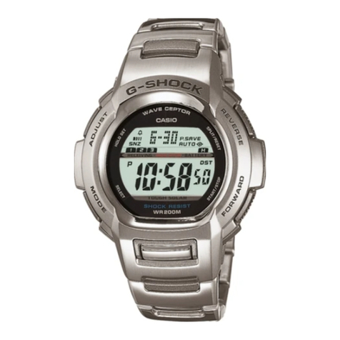
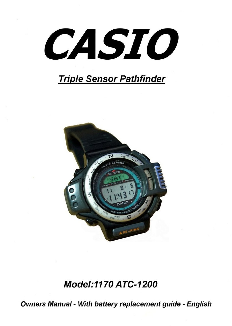
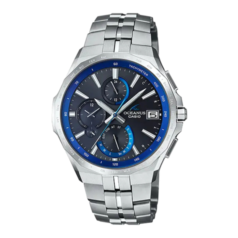
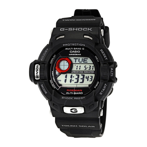
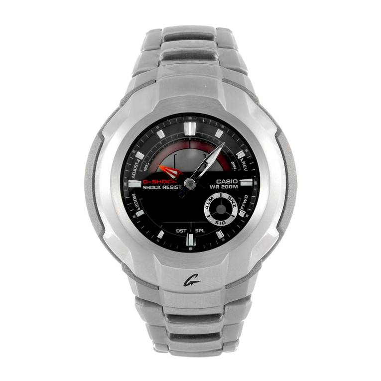
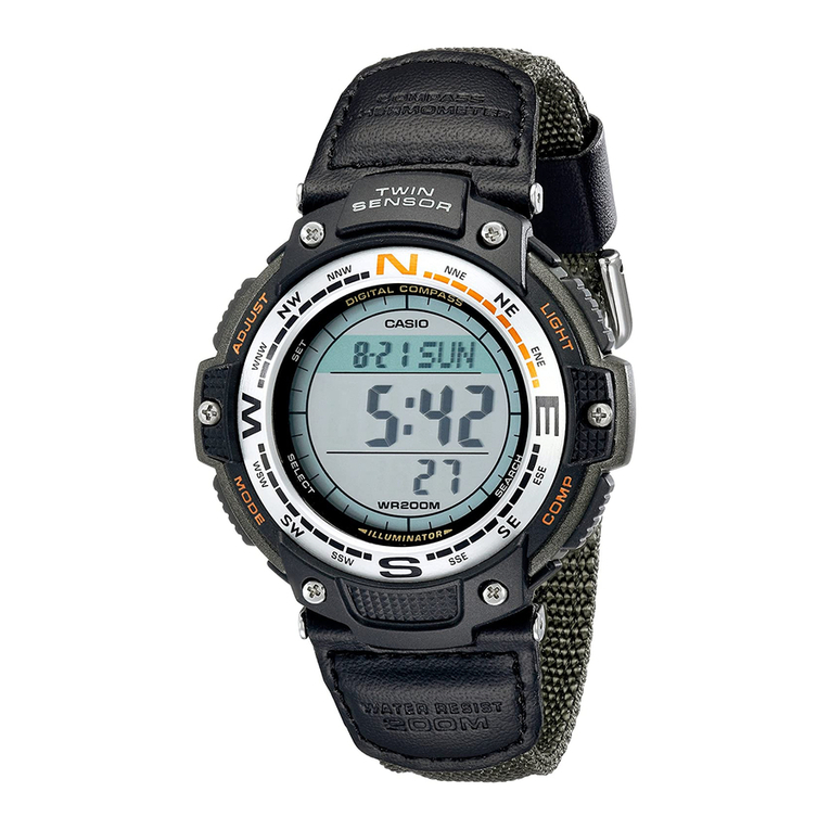
Casio GW-9400-1 Troubleshooting guide

SERVICE MANUAL
& PARTS LIST
(WITHOUT PRICE)
QW-3410
MODULE NO.
REF. NO. S/M-1228
OCT. 2013
GW-9400-1
Ver.1 : Feb. 2016

CONTENTS
Page
1. SPECIFICATIONS: MODULE QW-3410................................................. 1
2. DRAWINGS: MODULE QW-3410
2-1. LCD DIAGRAM...........................................................................................2
2-2. CHECKING TERMINALS AND COMPONENTS........................................3
3. EXPLODED VIEW: MODULE QW-3410................................................. 4
4. PARTS LIST: MODULE QW-3410 .......................................................... 5
5. REPLACEMENT OF BATTERY: MODULE QW-3410
5-1. OPEN DISPLAY........................................................................................7
5-2. AC (ALL CLEAR) .....................................................................................7
5-3. SETTINGS AFTER AC .............................................................................8
6. DISASSEMBLY AND REASSEMBLY: MODULE QW-3410
6-1. RREMOVING THE MODULE ..................................................................10
6-2. REMOVING THE SENSOR .....................................................................11
6-3. ASSEMBLING THE SENSOR.................................................................12
6-4. ATTACHING LED AND SPRING/COIL 5140-2 .......................................14
7. TESTING: MODULE QW-3410
7-1. MEASURING CURRENT CONSUMPTION...............................................16
7-2. ACCURACY CHECKING...........................................................................17
7-3. CHECKING THE LCD SEGMENTS ..........................................................18
7-4. CONFIGURING HOME CITY.....................................................................18
7-5. SOLAR CELL-PCB ASS’Y CONTACT CHECKING .................................19
7-6. HOW TO CHECK TILT SENSOR ..............................................................19
7-7. TIME CALIBRATION SIGNAL TEST ........................................................20

QW-3410
– 1 –
1. SPECIFICATIONS: MODULE QW-3410
Item Detail
Battery CTL1616 (Storage battery)
Note: Use CTL1616 only. Other storage battery or CR1616 can cause damage to the
watch.
Battery life Approx. 8 months
Current consumption 1.32 μA maximum
See page 16
Alarm system Piezo plate on Cover/Back
Accuracy ± 15 sec./month
Accuracy setting system Theoretical regulation
Accuracy checking See page 17
Functions • Timekeeping: Hour, minutes, seconds, p.m. (P), year, month, day, day of the week,
Time format: 12-hour and 24-hour
Calendar system: Full Auto-calendar pre-programmed from the year 2000 to 2099
• Time Calibration Signal Reception:
Auto receive 6 times a day (5 times a day for the Chinese calibration signal) ; Remaining auto receives cancelled as
soon as one is successful; Manual receive; Receive Mode
Receivable Time Calibration Signals:
Mainflingen, Germany (Call Sign: DCF77, Frequency: 77.5 kHz); Anthorn, England (Call Sign: MSF, Frequency: 60.0
kHz); Fort Collins, Colorado, the United States (Call Sign: WWVB, Frequency: 60.0 kHz); Fukushima, Japan (Call
Sign: JJY, Frequency: 40.0 kHz); Fukuoka/Saga, Japan (Call Sign: JJY, Frequency: 60.0 kHz); Shangqiu City, Henan
Province, China (Call Sign: BPC, Frequency: 68.5 kHz)
• Altimeter:
Measurement range: –700 to 10,000 m (–2,300 to 32,800 ft.) without reference altitude
Display range: –10,000 to 10,000 m (–32,800 to 32,800 ft.)
Negative values can be caused by readings produced based on a reference altitude or due to atmospheric condi-
tions.
Display unit: 1 m (5 ft.)
Altitude Memory Data:
Manual save records: 40 (altitude, date, time)
Auto save values: High altitude (with month, day, time of reading), low altitude (with month, day, time of reading),
cumulative ascent (with month, day, time of first reading), cumulative descent (with month, day, time of first
reading)
Other: Reference altitude setting; Altitude graph; Altitude differential; Altitude auto measurement method (0’05 or 2’00)
• Digital Compass: 60 seconds continuous measurement; Angle value 0° to 359°; Four direction pointers; Calibration
(bidirectional, northerly); Magnetic declination correction; Bearing Memory
• Barometer:
Measurement and display range: 260 to 1,100 hPa (7.65 to 32.45 inHg)
Display unit: 1 hPa (0.05 inHg)
Measurement timing: Periodic atmospheric pressure measurement (at two hour intervals); Real time measurement,
Barometric pressure sensor calibration, Barometric pressure graph, Atmospheric pressure differential graphic, Atmo-
spheric pressure tendency information
• Thermometer:
Measurement and display range: –10.0 to 60.0°C (14.0 to 140.0°F)
Display unit: 0.1°C (0.2°F)
Real time measurement, Temperature sensor calibration
• Bearing Sensor Precision: Direction: Within ±10°
Values are guaranteed for a temperature range of –10°C to 60°C (14.0 to 140.0°F)
North pointer: Within ±2 digital segments
• Temperature Sensor Precision:
±2°C (±3.6°F) in range of –10°C to 60°C (14.0 to 140.0°F)
• Pressure Sensor Precision:
Conditions (Altitude) Altimeter Barometer
Fixed
temperature
0 to 6000 m
0 to 19680 ft.
± (altitude differential × 2% + 15 m) m
± (altitude differential × 2% + 50 ft.) ft. ± (pressure differential × 2%
+ 2 hPa) hPa
± (pressure differential × 2%
+ 0.059 inHg) inHg
6000 to 10000 m
19680 to 32800 ft.
± (altitude differential × 2% + 25 m) m
± (altitude differential × 2% + 90 ft.) ft.
Effect of
variable
temperature
0 to 6000 m
0 to 19680 ft.
± 50 m every 10°C
± 170 ft. every 50°F ± 5 hPa every 10°C
± 0.148 inHg every 50°F
6000 to 10000 m
19680 to 32800 ft.
± 70 m every 10°C
± 230 ft. every 50°F
• Values are guaranteed for a temperature range of –10°C to 40°C. (14°F to 104°F)
• Precision is lessened by strong impact to either the watch or the sensor, and by temperature extremes.
• World Time: 48 cities (31 time zones)
Other: Daylight Saving Time/Standard Time
• Stopwatch:
Measuring unit: 1/100 second
Measuring capacity: 999:59’ 59.9”
Measuring modes: Elapsed time, split time, two finishes
• Countdown Timer:
Measuring unit: 1 second
Countdown start time setting range: 24-hour (1-minute unit)
• Alarms: 4 Daily alarms; Hourly time signal
• Sunrise time and Sunset time
from 2000/1/1 to 2099/12/31
• Illumination: LED ; Selectable illumination duration (approximately 1 second or 3 seconds); Auto Light Switch (Full
Auto EL Light operates only in the dark)
• Other: Battery power indicator; Power Saving; Low-temperature resistance (–10°C/14°F);
Button operation tone on/off
QW-3410
– 2 –
2. DRAWINGS: MODULE QW-3410
2-1. LCD DIAGRAM
COM
SEG
SEG35 ps
COM4COM3COM2COM1COM0
SEG36
COM
SEG
COM4COM3COM2COM1COM0
COM
SEG
x20y4x20y6 x20y3x20y7x20y5
SEG28
SEG27
SEG26
SEG25
SEG24
SEG23
SEG22
SEG21
SEG20
SEG19
SEG18
SEG17
SEG16
SEG15
SEG14
SEG13
SEG12
SEG11
SEG9
SEG8
SEG10
SEG7
SEG29
SEG6
SEG30
SEG2
SEG3
SEG5
SEG4
SEG31
SEG33
SEG32
SEG1
SEG0
baro°C
mute
x9y2
x10y2
x11y0 x11y2min x11y1
x12y0 x12y2e3 x12y1
ft
f3
c0autolightd0 b0
a0
g3
g0e0 f0
c1
x13y0
b1hpa
e1
a1meter
deg
g1dst f1
sun
x13y1
x20y2
a2
x20y1
x19y0
x13y2c3
x19y1
f2
x20y0
x18y0
g2
x19y2
a3
x18y1
x17y1
x14y0
x17y0
x14y1
x16y1e2
x14y2
x16y0
x17y2
x15y1
x16y2
x15y0 x15y2sig
sunset
point1
d7
d8
high
mid
low
b6c6 a6
g6h6 e6 f6
c7 b7g7
e7 a7f7hyp
a8b8col1 c8
f8g8pm1 e8
b9c9
g9ade9
inhg
d1
c2
d2
°F
d6
b2 x18y2
b3
point0
b4
c4
b5
c5
pm0
x10y1x10y0 col0
x9y1x9y0 a4
x8y2 x8y1x8y0 f4
x7y2 x7y1x7y0 e4
x6y2d4 x6y1x6y0
x5y2 x5y1x5y0 a5
x4y2 x4y1x4y0 f5
x3y2 x3y1x3y0 e5
x2y2
alm
d3
g4
snz
g5
d5 x2y1x2y0 minus0
x1y2 x1y1x1y0 ant
SEG40
SEG66
SEG65
SEG64
SEG61
SEG62
SEG58
SEG60
SEG63
SEG57
SEG56
SEG55
SEG54
SEG53
SEG52
SEG51
SEG50
SEG49
SEG48
SEG46
SEG47
SEG45
SEG44
SEG43
SEG42
SEG41
SEG59
SEG67
SEG68
SEG39
SEG38
SEG37
SEG34
k22 k20 k24k21 k23
k29
k30
k39
k40
k49
k50
k59
k0
k9
k10
k19
x0y7
x1y7
x2y7
x3y7
x4y7
x5y7
x6y7
x7y7
x8y7
x9y5 x9y3x9y6 x9y4
x10y7
x12y7
x16y7
k27 k25k28 k26
k33k31 k34k32
k37 k35k38 k36
k43k41 k44k42
k47 k45k48 k46
k53k51 k54k52
k57 k55k58 k56
k3k1 k4k2
k7 k5k8 k6
k13k11 k14k12
k17 k15k18 k16
x0y4x0y6 x0y3x0y5
x1y5 x1y3x1y6 x1y4
x2y4x2y6 x2y3x2y5
x3y5 x3y3x3y6 x3y4
x4y4x4y6 x4y3x4y5
x5y5 x5y3x5y6 x5y4
x6y4x6y6 x6y3x6y5
x7y5 x7y3x7y6 x7y4
x8y4x8y6 x8y3x8y5
x10y5 x10y3x10y6 x10y4
x11y4x11y6 x11y3x11y5
x12y5 x12y3x12y6 x12y4
x13y4x13y6 x13y3x13y5
x14y5 x14y3x14y6 x14y4
x15y4x15y6 x15y3x15y5
x16y5 x16y3x16y6 x16y4
x17y4x17y6 x17y3x17y5
x18y5 x18y3x18y6 x18y4
x19y4x19y6 x19y3x19y5
x9y7
x11y7
x13y7
x15y7
x14y7
x17y7
x18y7
x19y7
plus x0y2 x0y1x0y0 minus1
SEG36
COM2
COM3
COM4
COM0
SEG37
SEG38
SEG39
SEG5
SEG4
SEG3
SEG2
COM1
SEG40
SEG41
SEG42
SEG43
SEG44
SEG45
SEG46
SEG47
SEG48
SEG49
SEG50
SEG51
SEG68
SEG67
SEG66
SEG65
SEG64
SEG63
SEG61
SEG62
SEG57
SEG58
SEG59
SEG60
SEG55
SEG53
SEG54
SEG56
SEG52
SEG1
SEG0
SEG35
SEG34
SEG33
SEG32
SEG31
SEG30
SEG29
SEG28
SEG27
SEG26
SEG25
SEG24
SEG23
SEG22
SEG21
SEG20
SEG19
SEG6
SEG7
SEG8
SEG9
SEG10
SEG11
SEG12
SEG13
SEG14
SEG15
SEG16
SEG17
SEG18
x20x0
y0
y7
k15
k45
k0
k30
plus
minus1
baro
pm1
°C
°F
mid
low high
sunset
dst
pm0
minus0
min
col0
point0
inhg
hpa
ant
meter
ft
ps
deg
col1
hyp
h6
point1
snz alm sig mute autolight
a4
f4 b4
e4 c4
d4
g4 g3
d3
c3e3
b3f3
a3 a2
f2 b2
e2 c2
d2
g2
g5
d5
c5e5
b5f5
a5
f0 b0
a0
g0
e0 c0
d0
d1
c1e1
g1
a1
b1f1
a6
b6f6
g6
c6e6
d6d7
e7 c7
g7
f7 b7
a7
a8
b8f8
g8
c8e8
d8
c9
g9
ade9
b9
sun

QW-3410
– 3 –
2-2. CHECKING TERMINALS AND COMPONENTS
EMP
VSS
P40
VCC
PA2
VCC
VDD2
OVD
VSS
VSS
VSENS
VDD2
VDD
VSS
VR1OUT
VSC
VR2OUT
VSSVSSVSSVSS
VSS
PLL_C2
LPF2QNLPF2QP
LPF2INLPF2IP
ANT_C2
ANT_C1
PEAK_C
ANT2
SHPR_C
AGC
LPF_BB
ANT1
ANT2ANT2
P00
P34
P30
VSC
VSS
P32
P31
VC2
VDD1
VSS
VDD3
VSS
VDSP
VSS
VC4
VHF
VSS
VSS
P10
VCH
VSS P33
DET_C
P22
VSS
PLL_C1
VSS
VSSP33
ANT1
ANT2
P00
VSS
P10
VDD2
VSS
VDD
AC
EMP
PADMP1
P33
P32
VSS
PADMP1
VBAT
P30
P34
VSS
COIL
VDD2
P41(PN7)
PN5
PN3
VSS(PN1)
VCC(PN2)
PN4
P40(PN6)
PN8
VDD2
P22
PADBD1
VSS
PABBD1
VSS
P00
P10
VDD2
P31
XTB
VSS
XT
XT
VDSP
VC3
VSC
VCH
VSS
VSS
PRINTED AREA
FOR LOT No.
PADBD1
PABBD1
VCC
VSS
CUSHION 3145-1
CUSHION 3145-1
TAPE/ADHESIVE 4323
OSCILLATOR/CRYSTAL
SHEET/INSULATION 3766
SENSOR/TILT
Short pad for switching modules
VSS-EMP: Open
< front side >
< back side >

QW-3410
– 4 –
1a (10455089)
1b (10455092)
5 (10105010)
10 (10388831)
7 (10301378)
6 (10300759)
11 (10448755)
18 (10415262)
14 (10456277)
9 (10444615)
2 (10382262)
8 (10168959)
4 (10354207)
15 (72300511)
16 (72301004)
7 (10301378)
13 (10444614)
9 (10444615)
12 (10444613)
5 (10105010)
17 (10124960)
3 (10444618)
Casing parts: SENSOR/PRESSURE
3. EXPLODED VIEW: MODULE QW-3410

4. PARTS LIST: MODULE QW-3410
Q
W-3410A
T
1
Q
W-3410AT-01T
K
2
Q
W-3410AT-02T
K
Note: 1. Prices and s
p
ecifications are sub
j
ect to chan
g
e without
p
rior notice.
2. S
p
are
p
arts are classified as follows accordin
g
to their im
p
ortance in after-sales service.
A
Rank ----------------------------------------
-
Im
p
ortant
C Rank ----------------------------------------
-
Not Im
p
ortant
3. Batteries in Bulk
p
ack on the tra
y
will be su
pp
lied from our Overseas S
p
are Parts Section under char
g
e
basis. Batteries in Blister
p
ack will be su
pp
lied from our Sales De
p
artment.
4. As for order/su
pp
l
y
of s
p
are
p
arts, refer to the se
p
arate
p
ublication "GUIDE BOOK for s
p
are
p
arts su
pp
l
y
".
A
ttention to order
1. The most of normal re
p
air or initial re
p
air within 1
y
ear since released month can be done b
y
main
p
arts.
2. Minor
p
arts should be ordered carefull
y
in consideration of the actual usa
g
e of
y
our re
p
air and
y
our technical skills.
3. Main
p
arts should be ordered and stocked a
pp
ro
p
riatel
y
in consideration of
y
our
p
arts usa
g
e and re
p
air usa
g
e for
similar models.
MAIN PARTS
Item Code No. Parts Name S
p
ecification R
12
10458934 MODULE/WITHOUT MOVEMEN
T
QW-3410AT-01TK 1
A
10458935 MODULE/WITHOUT MOVEMEN
T
QW-3410AT-02TK 1
A
1a 10455089 LCD K3410-01THP 1
A
1b 10455092 LCD K3410-02THNP 1
A
MINOR PARTS
Item Code No. Parts Name S
p
ecification R
12
2 10382262
@
BATTERY/LITHIUM-METAL
(
2
)
CTL-920F/CS 1 1 C
3 10444618 CIRCUIT SUPPORTER 3414 RJQ568426-001V01 1 1 C
4 10354207 CONTACT/BATTERY
(
-
)
182
8
Q359948-004V06 1 1 C
5 10105010 CUSHION 2608 Q471029-1 2 2 C
6 10300759 CUSHION 3145-3 RJQ543393-001V01 1 1 C
7 10301378 CUSHION 4334-1 RJQ532458-001V02 2 2 C
8 10168959 HOLDER/BATTERY 2730 Q255819-2V05 1 1 C
9 10444615 INTER CONNECTOR 3414 RJQ568428-001V01 2 2 C
10 10388831 LABEL 3260 RJQ557190-001V01 1 1 C
11 10448755 LED RJQ558902*002ATTK 2 2 C
12 10444613 LIGHT GUIDE 3414 RJQ568427-001V01 1 1 C
13 10444614 REFRECTOR 3414 RJQ568553-001V01 1 1 C
14 10456277 REFLECTOR 3414-2 RJQ570923-001V01 2 2 C
15 72300511 SPRING/COIL 1253-2 Q439219-1 1 1 C
Notes: R - Rank
A: Important
C: Not Important
Q'T
Y
QW-3410
Q'T
Y
— 5 —

Item Code No. Parts Name S
p
ecification R
12
16 72301004 SPRING/COIL 1253-2 Q439219A-2 2 2 C
17 10124960 SPRING/COIL 2763-1 Q471262-1 2 2 C
18 10415262 SPRING/COIL 5140-2 RJQ552453-002V01 4 4 C
For the
p
rices and minimum order/su
pp
l
y
q
uantities of the above
p
arts, refer to the Parts Price List P.L.-719.
Notes: R - Rank
A: Im
p
ortant
C: Not Im
p
ortant
QW-3410
Q'T
Y
— 6 —

QW-3410
– 7 –
5. REPLACEMENT OF BATTERY: MODULE QW-3410
5-1. OPEN DISPLAY
This model is equipped with EEPROM. When the back cover is open, a message “OPEN” is displayed
on the LCD.
The watch is in the Timekeeping mode. Returns to the usual display when the cover is closed.
5-2. AC (ALL CLEAR)
Be sure to perform AC (All Clear) after a battery is replaced.
Unless AC is performed, the memory(s) and/or counter(s) may not be initialized and cause malfunc-
tions.
1) Touch the AC contact and the CIRCUIT SUPPORTER 3414 with metallic tweezers.
The contact should be made for about two seconds.
2) Close the back cover.
3) Press any button except Eto go to the Timekeeping mode.
Without pressing buttons, it takes approximately one minute to automatically go to the
Timekeeping mode.
* When removing the back cover, do not misplace the spring/coils.

QW-3410
– 8 –
5-3. SETTINGS AFTER AC
Function Settings
After AC Mode Timekeeping Mode (after pushing any button except E.)
Timekeeping Mode
Date and time: Friday, January 1, 2010 12:00:00 AM
Display Switching: date, day of the week, hour, minute, second
Home Time DST: AUTO
Power-saving: ON
Button Operation Tone: BEEP (ON)
Auto Light: OFF
Backlight afterglow: 1.5 sec (LIGHT1)
Battery Level: HIGH
Note: The voltage is checked with the timing of a minute carry,
and then the actual battery level is displayed.
Home City Code: TYO (UTC+9)
Latitude/Longitude: Latitude 35.7 degrees north,
longitude 139.7 degrees east
Temperature Unit: °C
Altitude Unit: m
Barometric Pressure Unit: hPa
Barometric Pressure Graph: OFF
Barometric Pressure Information: OFF
World Time
WT City Code: UTC
Time: 3:00:00 PM
DST: All Cities OFF
Stopwatch Setting: “Reset” (0H 00’ 00 00)
Countdown Timer Setting: “Reset” (0H 10’ 00)
Start Time: 0H 10’ 00
Alarm
Display: Alarm 1
Time: 12:00 AM (AL1-4, SNZ)
Alarm: OFF (AL1-4)
Snooze: OFF
Hourly Time Signal: OFF
Sunrise/Sunset
Calculation starts when the mode is switched from the Time-
keeping Mode.
Date: Home City
Sunrise/Sunset Time: cleared (Calculating)
Altitude recall
Setting: Blank pages
Manual Memory data: cleared
Auto Memory data: cleared
Signal Reception
Last Reception Display: “— : — — / — — — —”
Auto reception: ON (Home City Code/TYO)
Display: RECEIVED (Sweeping Display)
Altimeter
Altitude data: cleared
Altitude tendency graph: cleared
Altitude difference graph: cleared
Altitude unit: meters (m)
Altitude Offset: OFF
Baseline altitude of altitude difference indicator: 0 m
Display: Altitude tendency graph

QW-3410
– 9 –
Function Settings
Digital Compass
Magnetic Declination Angle Correction Value: 0°
Magnetic Declination Correction: OFF
Display: 4-directional graphic display
Barometer
Barometric Pressure / Temperature data: cleared
Barometric Pressure tendency graph: cleared
Pressure differential graphic: cleared
Barometric Pressure Unit: hPa
Temperature Unit: °C
Temperature / Barometric Pressure Offset: OFF
Barometric Pressure tendency Information: OFF

QW-3410
– 10 –
6. DISASSEMBLY AND REASSEMBLY: MODULE QW-3410
Note: The pressure sensor may be replaced separately.
The temperature sensor is mounted on the flexible board of the pressure sensor;
therefore, replacing the pressure sensor may repair some temperature measurement
failures.
The O ring for the back cover has 6H, and 12H sides.
Be careful to place the O ring in the right direction.
6-1. REMOVING THE MODULE
1) When removing the back cover, do not misplace the spring/coils.
SPRING/COIL 1253-2
(
Au
p
lated
)
SPRING/COIL 1253-2 (Ni plated)
BACK COVER
2) Release the Connector lock.
3) Remove the Sensor cable.
Sensor cable
Connector lock
4) Please insert a precision screw driver into the gaps pointed by arrows between the module and
the case.

QW-3410
– 11 –
6-2. REMOVING THE SENSOR
1) Remove the Bezel.
Bezel
The CAP/SENSOR may come off
the Bezel. Do not misplace it.
2) Undo two screws and the Plate/Protection.
Screws
Plate/Protection
3) Remove the Plate and O-ring.
Plate O-ring
4) Remove the Sensor.
Sensor

QW-3410
– 12 –
6-3. ASSEMBLING THE SENSOR
Please refer to the photo and the illustration below for the component structure of the Sensor.
sensor
plate
Screw
O-ring
plate/protection
Sensor
Plate/Protection
O-ring
Plate Screws
Cautions concerning Assembling
When replacing the sensor, fold the new sensor
cable into shape.
1) Secure the sensor in place.
2) Use a pin with 1-mm diameter to shape the
sensor cable.
Do not crease the sensor cable when shaping it.
1-mm-
diameter pin
Fold the FPC
Sensor
FPC
Sensor Side View
1) Set Sensor and O-ring.
Cautions concerning Assembling
The Flat surface of the O-ring faces the Plate.
2) Set Plate, giving attention to its direction.
Sensor
Plate
Flat surface

QW-3410
– 13 –
3) Position the Plate/Protection correctly on the plate, aligning the hook of the Plate/Protection to the
hook-hole of the case. The hook is on the Back Cover side.
4) Attach the Plate/Protection with two screws.
Plate/Protection
hook
Screws (same size)
5) Insert the sensor cable into the connector as far as it will go and then close the cover.
(The Back Cover side is the pad surface)
Note: Form the pressure sensor FPC into shape before installing it.
Connector cover
Bend it towards
the case back.
Sensor
FPC
Sensor Side View
Pad surface
Sensor cable
Connector cover
Insert as far as it will go

QW-3410
– 14 –
6-4. ATTACHING LED AND SPRING/COIL 5140-2
1) Remove the liner paper from the bottom surface (white part)
of the REFLECTOR 3414-2, and attach it to the HOUSING
3414-1 in the position shown in the illustration below. The
upper surface (the mirror surface) faces the Cover/Back.
9 H
HOUSING 3414-1
REFLECTOR 3414-2
Side view
HOUSING 3414-1
REFLECTOR 3414-2
Glass side
Cover/Back side
the mirror surface
white part
2) Attach LED to the HOUSING 3414-1.
Orientation of LED: the light-emitting surface (white part) faces inside, and the terminal surface
faces the Cover/Back.
9 H
HOUSING 3414-1
LED
Side view
HOUSING 3414-1
Light-emitting surface
Glass side
Cover/Back side
LED
Inside
Press the edge of the LED
against the end.
Configuration diagram
HOUSING 3414-1
REFLECTOR 3414-2
LED

QW-3410
– 15 –
3) Attach the LCD to the HOUSING 3414-1.
Attach the LIGHT GUIDE 3414 to the LCD.
LCD
LIGHT GUIDE 3414
HOUSING 3414-1
4) Attach the REFRECTOR 3414 and the CUSHION 4334-1.
REFRECTOR 3414
CUSHION 4334-1
5) Attach INTER CONNECTOR 3414 to the LIGHT GUIDE 3414.
INTER CONNECTOR 3414
6) Attach the SPRING/COIL 5140-2 for the LED to the LIGHT GUIDE 3414.
Note: Do not misplace the parts when assembling.
LIGHT GUIDE 3414
9 H
HOUSING 3414-1
SPRING/COIL 5140-2

QW-3410
– 16 –
7. TESTING: MODULE QW-3410
7-1. MEASURING CURRENT CONSUMPTION
If irregularity of current consumption is suspected, measure the current consumption.
• Condition
Short-circuit the MP and VSS terminals using a metal object like a staple.
MP terminal
VSS terminal
staple
tape
Use a stable power source and an ammeter.
Connect the positive electrode to the HOLDER/BATTERY 2730, the negative electrode to
the CIRCUIT SUPPORTER 3414.
V
(_)
(+)
A
HOLDER/BATTERY 2730
CIRCUIT SUPPORTER 3414
1) Apply a voltage of 2.5.
2) Perform AC.
3) Wait two seconds.
4) Shield the dial from light.
5) Measure the current.

QW-3410
– 17 –
7-2. ACCURACY CHECKING
Check the accuracy of the module with a quartz timer after switching the module to [ ACCURACY
CHECKING MODE ].
The operations are shown below:
1) SWITCHING TO [ ACCURACY CHECKING MODE ]
While pressing the button, press and buttons
in
the normal timekeeping mode.
Then the LCD drive signals are changed to 1/4 duty drive signals so that
you can check the accuracy with the quartz timer.
Measure the accuracy value on the following conditions.
SENSOR GATE TIME
LCD 16 seconds
2) CANCELLATION OF THE [ ACCURACY CHECKING MODE ]
Press
, , , or .
Then the watch returns to the Timekeeping mode.
The watch will also automatically return to the timekeeping mode in 1 ~ 2 hour(s) without any op-
eration.
Accuracy cheak
(1/4Duty)
Timekeeping
mode
Light alternates All lit
(1/5Duty)
Module No.
(3414 3)
Home city
Home city change
NYC / LON / BER / HKG / TYO
++
Any Button
Except for
Except for
,
Except for
,
Except for
,
ROM Ver.
No test is performed
QW-3410

QW-3410
– 18 –
7-3. CHECKING THE LCD SEGMENTS
• All lit : Check that all the segments are lit.
• Light alternates: Check that only the specified segments are lit.
< All lit > < Light alternates >
7-4. CONFIGURING HOME CITY
1) While in the Timekeeping mode, hold down and press and at the
same time.
2) Press
.
The Home City is displayed on the LCD.
3) Each time
is pressed, the Home City switches in the order below.
NYC LON PAR HKG TYO
Configuration of each home city
HOME CITY LCD Calibration signal DST Setting
(After AC)
NYC NYC WWVB
OFF
LON LON MSF
BER BER DCF77
HKG HKG BPC
TYO TYO JJY40/60
4) Exiting the Test mode.
Press to return to the accuracy checking mode.
QW-3410
This manual suits for next models
1
Table of contents
Other Casio Watch manuals

Casio
Casio Edifice EQW-510Y-1AV User manual

Casio
Casio 4391 User manual

Casio
Casio 5455 MTG User manual

Casio
Casio 3206 User manual

Casio
Casio 5142 User manual

Casio
Casio W211-2BV User manual

Casio
Casio QW-1219 Configuration guide

Casio
Casio 2362 User manual

Casio
Casio QW-734 Configuration guide

Casio
Casio 4752 User manual

Casio
Casio 5040 User manual

Casio
Casio QX-509 User manual

Casio
Casio DBC32-1A User manual

Casio
Casio AQS800WD-1EV User manual

Casio
Casio Analog (MAB) User manual

Casio
Casio QW-761 Configuration guide

Casio
Casio Analog (MAC) 5125 User manual

Casio
Casio 3128 User manual

Casio
Casio 5187 User manual

Casio
Casio 4312 User manual