CAVIDYNE Caviblaster 1222-E Manual

Model 1222-E
Operation & Maintenance Manual
www.cavidyne.com

1222-E OPERATING INSTRUCTIONS
WARNING: To ens re operator safety and efficient operation of the
CaviBlasterTM, it is essential to follow these instr ctions.
Preparing the CaviBlasterTM system for operation:
1. Inspect the CaviBlasterTM power unit, hoses and Zero Thrust Gun for any signs of damage.
. Inspect inlet strainer (Figure 1) to ensure that it is not clogged. Clean if necessary.
3. Check for proper oil level in pressure pump (Figure ).
4. Fill lubricating oil to proper level in the pressure pump (yellow cap on pump) (Figure 3) per
manufacturer’s operating manual. **SAE 30W Non-detergent oil**
Figure 1 Figure Figure 3
5. To supply water to the CaviBlasterTM power unit, connect a 1″ ( 5 mm) diameter feed hose to
the cam-lock plug on the inline strainer inlet (Figure 4). Either fresh water or seawater can
be used with this system. The water source must supply the CaviBlasterTM with water at a
volume of greater than 1 gallons (45 liters) per minute at a maximum pressure of 70-psi (5
bar). Ensure that the feed hose is connected to the pressure pump and the water is on prior to
starting the pressure pump.
6. Connect the 1″ ( 5 mm) red rubber bypass hose to the cam-lock plug on the pressure-
regulating unloader (Figure 5). The bypass hose has a cam-lock socket on one end. Direct
the bypass hose away from the working area and secure the hose.
Page -

Figure 4 Figure 5
Starting the CaviBlasterTM power nit:
1. Turn on the water supply to the system.
. Ensure that the system is primed with water
and that there are no leaks in the system. The
pressure pump is a positive displacement pump
and water must be supplied under pressure.
Fail re to p mp feed water to the press re
p mp will res lt in damage to the p mp.
3. Once the system is primed, turn off the water
supply to the system.
Figure 6
4. Connect the ½″ (13 mm) high-pressure hose to
the quick-connect plug under the pressure-
regulating unloader ( Figure 6 ). The high -
pressure hose has a brass quick-connect socket
on the end. The 1 -E CaviBlasterTM can
deliver the required pressure utilizing up to 300
feet (100 meters) of ½″ diameter rubber hose or
600 feet ( 00 meters) of thermoplastic hose.
Using greater lengths or smaller diameters
of hose may degrade performance. If greater
hose lengths are required, ¾” (19 mm)
diameter hose must be used.
5. Connect the Zero Thrust Gun to the high
pressure hose (Figure 7) and submerge the
Zero Thrust Gun in water. Figure 7
6. Restart the water supply.
Page - 3

7. Connect the power cable for the motor to the
power source.
8. It is recommended that the Zero Thrust Gun trigger
be in the open or “ON” position (Figure 9) when
starting the motor.
9. Depress the green “START” button on the motor
controller (Figure 8) mounted on top of the motor
to start the motor.
10. The system is now ready to operate (refer to photo
on cover for overall system set-up).
Figure 8
Figure 9
WARNING: Altho gh the CaviBlasterTM system is safe to se when
s bmerged in water, the system generates a high-
press re ( p to 2,200-psi) water stream, which can ca se
inj ry when the Zero Thr st G n is o t of the water.
ALWAYS keep the Zero Thr st G n s bmerged when the
press re p mp is engaged.
Page - 4

Operating the CaviBlasterTM system:
1. When the diver is ready to commence cleaning operations, ensure that the Zero Thrust Gun is
submerged in water. If the diver is not wearing a helmet, hearing protection is
recommended. Cavidyne recommends “Doc’s Proplugs” vented earplugs for diver hearing
protection.
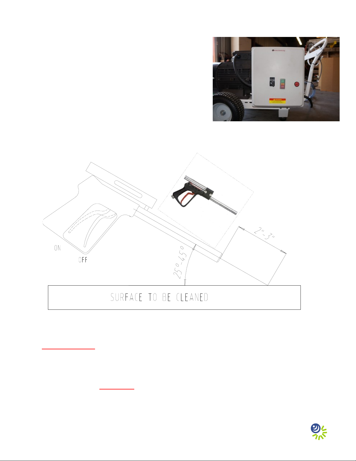
. Activate the cleaning cavitation stream by squeezing the trigger to the open or “ON” position
(Figure 9).
3. The most efficient operating technique is to hold the Zero Thrust Gun -3 inches (5-8 cm)
away from the surface to be cleaned and at a 5 to 45 degree angle to the surface being
cleaned (Figure 9). Placing the Zero Thrust Gun closer than -3 inches from the surface
being cleaned will not allow for efficient cavitation performance and will degrade the
cleaning capability of the system.
4. Wear neoprene or rubber gloves to protect the hands and follow all safety regulations that
may be applicable to the work being performed.
5. If the diver operating the unit must be replaced or the cleaning operation must be interrupted
for a prolonged period or terminated, shut down the motor by depressing the red “STOP”
button (Figure 8) on the motor controller. Turn off the water supply to the pump, and then
release the water pressure in the hose(s) by squeezing the Zero Thrust Gun trigger to the open
or “ON” position (Figure 9) while nder water. Revert back to step 1 of the operating
instructions when the replacement diver is ready to continue cleaning.
6. Ensure that the Zero Thrust Gun is submerged any time the motor and pressure pump are
operating.
Adj sting the CaviBlasterTM system for maxim m performance:
1. If using a calibration pressure gauge situated between the pressure hose and the CaviBlasterTM
Zero Thrust Gun, the water pressure should be , 00-psi with the Zero Thrust Gun
submerged and the Zero Thrust Gun trigger in the open or “ON” position. The pressure is
adjusted by turning the nuts on the end of the pressure-regulating unloader (Figure 5) to
compress or relax the green spring. This adjustment increases or decreases the flow of water
through the bypass hose when the CaviBlasterTM Zero Thrust Gun trigger is in the open or
“on” position. The flow of water through the bypass hose, in turn, determines the flow of
water through the pressure hose and the Zero Thrust Gun. Less flow through the bypass hose
means more flow through the Zero Thrust Gun which translates to higher velocity and
pressure. Turn the nuts to compress the spring to decrease the amount of water passing
through the bypass and increase the water flow and pressure at the Zero Thrust Gun. Turn
the nuts to relax the spring to increase the amount of water passing through the bypass and
decrease the water flow and pressure at the Zero Thrust Gun. There should always be a
trickle of water through the bypass when the Zero Thrust Gun trigger is in the open or “ON”
position. This ensures that the bypass will open without a pressure shock wave damaging the
pump when the Zero Thrust Gun trigger is released to the closed position.
Page - 5

. If using a pressure gauge located on the CaviBlasterTM power unit, the water is adjusted as
described in step 1 above. However, pressure will need to be higher to account for sidewall
friction loss in the pressure hose. The pressure at the pump should be , 00-psi plus 0.75-psi
per foot of thermoplastic pressure hose. For example, if using the CaviBlasterTM with 100
feet of pressure hose, the pressure gauge located next to the pump should indicate , 75-psi.
Pressure adjustments are made in the same manner as described above. There should always
be a trickle of water through the bypass when the Zero Thrust Gun trigger is in the open or
“ON” position.
3. If adjusting the CaviBlasterTM without a pressure gauge, close the pressure-regulating
unloader until there is just a trickle of water (less than ¼ gallon or 1 liter per minute)
coming out of the bypass with the Zero Thrust Gun trigger in the open or “ON” position.
Sh tting down the CaviBlasterTM power nit:
1. Stop the motor by depressing the red “STOP” button (Figure 8) on the motor controller.
. Shut off the supply of water to the pump.
3. Squeeze the Zero Thrust Gun trigger to the open or “ON” position (Figure 9) to release the
water pressure remaining in the hose(s) while the Zero Thr st G n is s bmerged.
4. It is now safe to remove the Zero Thrust Gun from the water.
5. Flush the system and rinse the power unit with fresh water at the end of the day.
Maintenance of the CaviBlasterTM nit:
1. Empty and clean the inline strainer every day.
. Check the pressure pump oil level and consistency every day.
3. Flush the system and rinse the power unit with fresh water after each days use.
4. Inspect the pump drive belt every week and replace the belt when cracking appears.
5. Change the oil in the pressure pump after the first 50 hours and every 500 hours thereafter.
6. Change the spring for the Zero Thrust Gun trigger every 1 months or less if required.
Page - 6

S mmarizing the operating instr ctions:
1. Inspect the system for damage. Clean the inlet strainer. Check pressure pump
oil level.
. Attach the feed and bypass hoses.
3. Start the water supply and ensure that the system is primed (water should be
coming out of the pressure hose quick-connect plug).
4. Attach the pressure hose and Zero Thrust Gun.
5. Connect the power cable to the power source.
6. Make sure that the diver is ready to work and that the Zero Thrust Gun is
submerged in the water. Apply hearing protection if the diver is not wearing a
helmet.
7. Start the motor.
8. Activate the cleaning cavitation stream by squeezing the Zero Thrust Gun
trigger to open or “ON.”
9. Proceed with cleaning.
10. Stop the motor.
11. Shut off the water supply to the pump.
1 . Release pressure from the hose(s) by squeezing the Zero Thrust Gun trigger to
the open or “ON” position while nder water.
13. Remove the Zero Thrust Gun from the water.
14. Disconnect the power cable from the power source.
15. Flush the system and rinse the outside of the power unit with fresh water.
Page - 7

WARNING
While the CaviBlasterTM system is very safe, operators should exercise care when using the equipment.
The cavitation “flame” can be safely passed over the operators’ skin at normal operating distances of ” -
3” (5 - 8 cm) from the tip of the nozzle. However, at very close distances (typically less than 1”) both
nozzles are capable of causing harm to the operator, particularly in the initial instant that the system is
activated. For that reason, operators sho ld exercise ca tion when operating the Zero Thr st G n
with the nozzles in close proximity to the body. The operators sho ld also ens re that the reverse-
thr st nozzle g ard is sec red in the correct position prior to operating the Zero Thr st G n.
The operators of the CaviBlasterTM system should always wear neoprene or heavy rubber gloves to
provide protection to the hands and, in particular, to the nails. The gloves will absorb most of the energy
produced by bursting cavitation bubbles and prevent the cavitation bubbles from contacting the operators’
hands. The gloves will also protect operators’ hands from the initial shockwave when the Zero Thrust
Gun is activated.
Serio s harm and inj ry may res lt from the mis se of CaviBlasterTM system eq ipment or
improperly selected fittings, hoses or attachments. All components of the system should be checked
against the manufacturers’ instructions to ensure that they are compatible with the pressures being used
and of the correct thread type and pressure rating for the intended service. Refer to these Operating
Instructions and to the motor and pressure pump manufacturers’ operation manuals for instructions or call
CaviDyne, LLC at (35 ) 75-5319 with any questions.
CAUTION:
DO NOT U E THI EQUIPMENT TO CLEAN
EN ITIVE URFACE as LED-Lights,
Underwater Lights, Elecronic Equipment, Etc.
Page - 8

Page - 9
Other CAVIDYNE Portable Generator manuals
Popular Portable Generator manuals by other brands

Millenium Signatures
Millenium Signatures MS-510 instruction manual

Baumer
Baumer HUBNER TDP 0,2 Series Installation and operating instructions

Daewoo
Daewoo GDA Series user manual

Parkside
Parkside PGI 1200 A1 Operating and safety instructions

Dometic
Dometic TEC Series installation manual

Robin America
Robin America GENERATORS 13OOOT Service manual