Cavius 9005 CAVRI User manual

1
PLEASE READ THIS USER GUIDE CAREFULLY
RELAY INTERFACE

2
CONTENTS
1. PRODUCT FEATURES AND SPECIFICATIONS 3
2. OPERATIONAL 5
3. HOW TO SET UP RELAY AND CONNECT CAVIUS WIRELESS FAMILY ALARMS 7
4. INSTALLATION INSTRUCTIONS 8
5. TEST FUNCTION 13
6. ADD EXTRA DEVICE 14

3
1. PRODUCT FEATURES AND SPECIFICATIONS
Model: 9005 CAVRI. Mains powered relay interface with RF interconnect.
The 9005 CAVRI Relay Interface is primarily intended to enable a connection
between an external system or devices and the CAVIUS Wireless Family.
•Electrical Rating: 230 VAC, 50 Hz, 1.8 W
•Battery Life: 1-year life in battery mode without mains power, and up to 10-years
normal life with mains power.
•Replacement Battery: CR2
•Relay Contacts rating: 250 VAC @ 5 Amps or 30 VDC @ 5 Amps
•Trigger I/P voltage: 3 to 30 V DC
•Low Battery : A short beep will sound out every 48 seconds for 30 days.
•Red LED for RF Learn Mode / Alarm / Fault
•Green LED for mains power on.
•Test button is used to setup wireless interconnect, and test.
•Wireless Radio Frequency: 926.365 MHz
•Wireless Interconnect: up to 32 units
•Operating Temperature Range: 0°C to 40°C
•Humidity Range: 0% to 90% RH, non-condensing
•Latched or Pulsed relay output (user selectable), see Section 2, Figure 2.

4
Features
FIGURE 1
Front Side
145 mm
27 mm
115 mm
cover screw
Sounder
Pulse switch
Learn switch
Back up battery
Test button
Inside

5
2. OPERATIONAL
The 9005 CAVRI relay can be RF interlinked with other CAVIUS Wireless Family alarms.
The maximum number of alarms that can be interlinked within a house group is 32 units.
The wireless distance between interlinked alarms depends on the house layout and they should
always be tested after installation. It is not advisable to install alarms with a separation of more
than 10m. Please note: These must be alarms from the CAVIUS Wireless Alarm Family.
The 9005 CAVRI Relay provides a set of Normally Closed (NC) and Normally Open (NO) change
over contacts. This enables CAVIUS smoke and heat alarms to trigger auxiliary devices such
as Telecare Systems, strobe lights, sounders, re alarm panels, activate emergency lights, shut
down air conditioners or release magnetic door holders. Third party devices such as sprinkler
ow switches or re panels can also be connected to the trigger input to cause the CAVIUS
alarms to sound when activated.
This relay has 2 selectable modes of operation.
Select the mode of operation using PULSE switch (See Figure 2).
Pulse OFF:
Relay activates continuously
when the smoke and /or heat alarm
is in the alarm condition
Pulse ON:
Relay activates for approximately 5 seconds when
the smoke and /or heat alarm is in the alarm condition.
ON
OFF
ON
OFF
See user guide
for more information.
PULSE MODE
NORMAL
LEARN
FIGURE 2
Pulse switch

6
LED indication
There are two LED that indicate the following.
Green
•ON – AC Power/mains supply is present
•OFF – AC Power/mains supply is not present
Red
The Red LED indicates the following
conditions.
•Learn mode condition:
Red LED on.
•Trigger input detected:
The Red LED will flash every 0.5 seconds
if a trigger input from an external device is
detected. Note: The Relay Interface red LED will not illuminate if the relay is activated by
CAVIUS smoke or heat alarms.
•Battery fault:
In normal operation the red LED will flash every 48 seconds. If the battery is in a low voltage
condition or faulty, the red LED will flash every 48 seconds and the sounder will chirp in time.
FIGURE 3
Red LED : Alarm /
Learn Mode / Battery fault
Green LED:
Mains power on

7
3. HOW TO SET UP RELAY AND CONNECT
CAVIUS WIRELESS FAMILY ALARMS
The Relay & all alarms that need to be connected in the
house should be put into “Learn Mode” by sliding the
switch on the inside of the relay (Figure 4) and back of
the alarms to the “LEARN” position.
The red LED will illuminate to indicate that ‘Learn Mode’
has been selected.
Press and hold the test button on one device only,
until it beeps and the LED flashes. This device
will become the master and will start sending out
a specific house code to the other RF device.
See Figure 5.
As the other device receives the specific house code,
they will also flash the LED light.
When the red LED light flashes on RF Relay Interface and
all CAVIUS Wireless Family alarms, they are connected
and MUST BE SWITCHED OUT OF ‘LEARN MODE’ and
installed. See Figure 4.
Leaving the RF relay in learn mode for an extended
time will reduce the battery life. TEST Button
ON
OFF
See user guide
for more information.
PULSE MODE
NORMAL
LEARN
FIGURE 4
FIGURE 5
Learn switch

8
4. INSTALLATION INSTRUCTIONS
The 9005 CAVRI RF relay must be on a circuit breaker and be installed in a suitable location
according to local building regulations and codes of practice.
!
WARNING: Disconnect mains power before commencing work.
A. Remove cover (cover screw) to allow access to wire connections. See Figure 6.
FIGURE 6

9
Mark and drill two holes for wall or ceiling anchors.
6.80mm
25mm
18mm
B. Mount in required location.
C. After the cables are connected, press the Test button. Please re-install the module
cover.
FIGURE 7

10
Wiring Instructions:
!
WARNING: Alarm and relay module wiring installation must comply with the current
edition of AS3000, Wiring Regulations and all appropriate prevailing local/national building
regulations and codes of practice.
Product must be installed by a qualified electrician. Failure to install this product correctly
may expose the user to electric shock or fire risk hazards. This relay module is not rated as
waterproof and must not be exposed to dripping or splashing water. The relay module must
be installed correctly to function. The electrical circuit used to power the relay module must
be 240 volt AC 50Hz.
!
WARNING: This product cannot be operated from power derived from a square wave,
modified square wave or modified sine wave inverter. These type of inverters are sometimes
used to supply power to the structure in ‘off grid’ installations, such as solar or wind derived
power sources. These power sources produce high peak voltages that can damage the
device.
!
IMPORTANT: It is recommended that the module and alarms are connected to a
dedicated circuit that is separately electrically protected. This helps minimise interference
(EMI) on alarm interconnect line from CFL’s, dimmers, LV transformers etc.
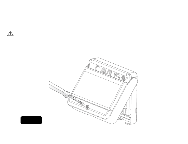
Make sure that AC power is turned off before starting the installation.
This 9005 CAVRI Relay Interface will not detect smoke or heat. This wireless module can only
interconnect with compatible smoke alarms or relay. Interconnection with other brands may
cause damage, result in electric shock, fire risk and void warranty.
The earth terminal connection provided is for termination purposes only and is NOT
electrically connected within the sealed alarm / base units.

11
Terminals on the module are marked as shown in gure 9:
MARKINGS
Output Relay
NO Normally Open
C Common
NC Normally Closed
Input Trigger
SW Switch Return
3V Switch Feed
Voltage Trigger
0V 0V
+V +3 V to +30 V
AC Mains
L Live
N Neutral
Earth
!
WARNING: Connecting the switch terminals to any other supply conductor may result in
damage to the alarm, failure to operate or shock hazard and void the warranty of the alarm.
RELAY OPERATION
The RF relay may take a few seconds to operate when the smoke alarm or heat alarm is
activated or reset. This is normal operation.
FIGURE 8
ON
OFF
See user guide
for more information.
PULSE MODE
NORMAL
LEARN
CN/C
NO
VOLT FREE
FIRE
SW 3V
VOLT I/P
0V +V
N
TEST
L
RF relay interface
Power supply:
230VAC, 50Hz, 1.8W
Max. relay loading:
250V AC @ 5Amps
30V DC @ 5Amps
Model: 9004
Manufacturer:
Carrier Fire & Security
Danmark A/S,
Ellekær 9A, 2. Th, DK-2730.
Manufactured in China

12
CNC
NO
VOLT FREE
FIRE
SW 3V
VOLT I/P
0V +V
NL
230V AC
External Device
(strobe sounder, etc.)
External Device
(fire panel, etc.)
External Device
(sprinkler flow-switch, etc.)
By installing the RF relay in this manner it will allow you to operate devices such as telecare
systems, sounders, strobes, or any devices which do not exceed 250VAC @ 5 Amps.
The wiring connecting the module with the external device is not advised. Be sure to test
the operation of all the devices controlling the module or controlled by the module. Devices
controlled by the module can be tested by pushing the Test button on the relay and verifying
that the controlled device responds in the desired manner.
RF RELAY
RF SMOKE OR HEAT ALARM
FIGURE 9

13
5. TEST FUNCTION
After installation, test the RF relay and alarms to ensure they are
operating correctly and are within range of each other.
Press the test button on the relay for two sets of sweeps and until the
sounder stops. Release the button and this will send out the test signal
to all connected alarms.
When the test signal is sent out, the relay will respond in two ways:
a. A single beep every 8 seconds indicates that the relay is connected
and functioning.
b. Three short beeps every 8 seconds indicates a relay fault.
The test function will time out after 2 minutes, but can be stopped earlier by a short press of
the test button on the relay.
After system tests are complete, close the cover and tighten the securing screw to limit
access.
ENVIRONMENTAL PROTECTION
Waste electrical products should not be disposed of with household waste.
Please recycle where facilities exist. Check with your local authority or retailer
for recycling advice

14
6. ADD EXTRA DEVICES
All CAVIUS interconnected alarms within
the can be added to the system
as they run on same frequency and use the
same data protocol.
Place all Wireless Family alarms & Relay to
be interconnected into ‘Learn Mode’ and
repeat section 3. Always test connection to
all devices by Test button (section 5).
HEAT ALARM
SMOKE ALARM
MAINS POWERED
SMOKE ALARM
MAINS POWERED
HEAT ALARM
CAVIUS WIRELESS FAMILY
10 YEAR PHOTOELECTRIC
SMOKE ALARM
CAVIUS WIRELESS FAMILY
MAINS POWERED
PHOTOELECTRIC SMOKE ALARM
Developed & Manufactured by:
Carrier Fire & Security Danmark A/S,
Ellekær 9A, 2. Th, DK-2730, Denmark
cavius.com - [email protected]
Manufactured in P.R.C.
Distributor information:
for New Zealand - CAVIUS Nano Ltd.
58a Poplar Lane, Papamoa 3187, NZ. www.cavius.co.nz
for Australia - CAVIUS Australia PTY LTD
GPO Box 303, Brisbane, QLD 4001, Australia. www.cavius.com.au

15
Warranty:
CAVIUS provides a 10-year warranty against defect in faulty material and workmanship from the date of
purchase, on all devices.
The warranty applies to reasonable and normal conditions of use only. It does not include damage as a result
of misuse, incorrect installation, accidental damage, neglect, unauthorised deconstruction or dismantling
and any airborne or other contamination however this may have occurred.
If this product has an acknowledged defect it must be returned to the national CAVIUS Distributor at the
purchasers cost with the proof of purchase.
If the product has become defective within the 10-year warranty, CAVIUS APS, Denmark will repair or replace
the unit without charge and send back to the purchaser, via the national Distributor at the Distributors cost.
The guarantee excludes labour costs, freight costs, service costs and any incidental and consequential
damages. Do not attempt to repair or service this product as this will invalidate the warranty.
Under some unusual circumstances the presence of high levels of radio spectrum pollution may result in the
batteries within the CAVIUS device not lasting as indicated in the product sheet. Radio spectrum pollution
comprises transmissions inside the band allocated for alarm devices such as the CAVIUS devices. Such
transmissions may activate the receiver inside the devices for a longer time than is normal in standby.
This is not a specic problem for CAVIUS devices but for all similar radio linked technology powered by
batteries. The limited warranty will not cover the battery life period indicated in the product sheet in these
situations.
This warranty is in lieu of any other warranty either expressed or implied.
You can register your CAVIUS devices on our website.

16
REGISTER YOUR CAVIUS PRODUCT WITH US
& GO INTO THE DRAW TO WIN
FIND DETAILS AT
CAVIUS.CO.NZ/WARRANTY
Table of contents