CBT Supply FIK-18 User manual

©2009 CBT Supply Inc.
Installation Manual for
flipIT- Kit Generation II
FIK-18 keyboard tray actuated flipIT®
FIH-18 handle actuated flipIT®without keyboard tray
FIK-19 keyboard tray actuated flipIT®
FIH-19 handle actuated flipIT®without keyboard tray
FIK-23 keyboard tray actuated flipIT®
FIH-23 handle actuated flipIT®without keyboard tray
How to install into any desktop using templates
for cutting table top and pilot holes.
How to install into factory cut table top
with pilot holes.
ATTENTION:
LCD must be installed in order f or the flipIT lid
to remain closed. The LCD counterbalances
the force of the pneumatic cylinder.US Patent Pending
GENERATION I I
Note:
flipIT 19 and 23 for WideScreens install
as illustrated by the flipIT 18. The width
of the cutout and keyboard are the main
differences. The template(s) provided
work in a similar way. On the flipIT 19
and 23 templates, keyboard pilot holes
are printed on the same template with
the cutout markings. 2 templates are
provided for FIK-19 and 23, one is pro-
vided for the FIH-19 and 23.

2©2009 CBT Supply Inc.
WARNING
POWER TOOLS ARE DANGEROUS.
Review the safety procedures supplied by your power tools’ manufacturers. Heed all
warnings for your safety’s sake. Always use safety glasses and wear proper
apparel that won’t get caught in moving parts. CBT Supply, Inc. will not be held liable
for misuse of tools and disregard f or power tool manufacturer’s safety precautions.
Getting Started
Tools Needed for
Full Installation
Tools needed for
pre-assembly:
• Power Drill
• T
ape Measure
• Commercial-grade Jigsaw
• Phillips bit dr iver
• 3/8” Drill Bit
• 1/8” Drill Bit
• Pencil
• Permanent Marker
• Masking Tape
• Glue stick
Tools needed for installation
into factory cut desktop only:
• Screw gun or #2 Phillips
screw driver
• 3/8” open end wrench
These installation instructions guide you through the proper way of completing the
assembly of the flipIT®Kit FIK-18 (with keyboard) and FIH-18 (without keyboard,
plus cable release actuator handle). Improper installation may void the warranty. It is
especially important that the installer obser ve proper care in protecting surfaces from
abrasion.
For any questions or assistance, please contact Technical Service at 800-770-7042
ext 810.
STOP!
The installer must possess the
skill to cut within the toler ance
of the template layout line if no
factory-made cutout is made in
the table top. Do not attempt
this installation without this
level of craftsmanship skill.
If a factory made cut is provid-
ed, only skills of using a scre w-
driver and wrench are required.

flipIT Tech Line: 800 770-7042 3
©2009 CBT Supply Inc.
These instructions make certain assumptions about the working space. You can
make variations in these based on your application, but here is a reference of the
space allocation as designed for a standard installation. If you are placing two or
more flipIT units side-by-side, 30” spacing is recommended as a minim um.
The mouse tray extends on left or r ight. Seat users so left- and r ight-handed
do not conflict.
IMPORTANT:
Planning Ahead
Whenever possible, install the flipIT mechanism FIRST, before assembling the
desk. It’s easier and more efficient to w ork this way.
If you are installing flipIT into an assemb led desk, see if it is possib le to remove the
desktop to make the cut-out. If that is not possible, take care to make a work envi-
ronment that will protect the surface finish of your furniture and will be safe for oper-
ating power tools.
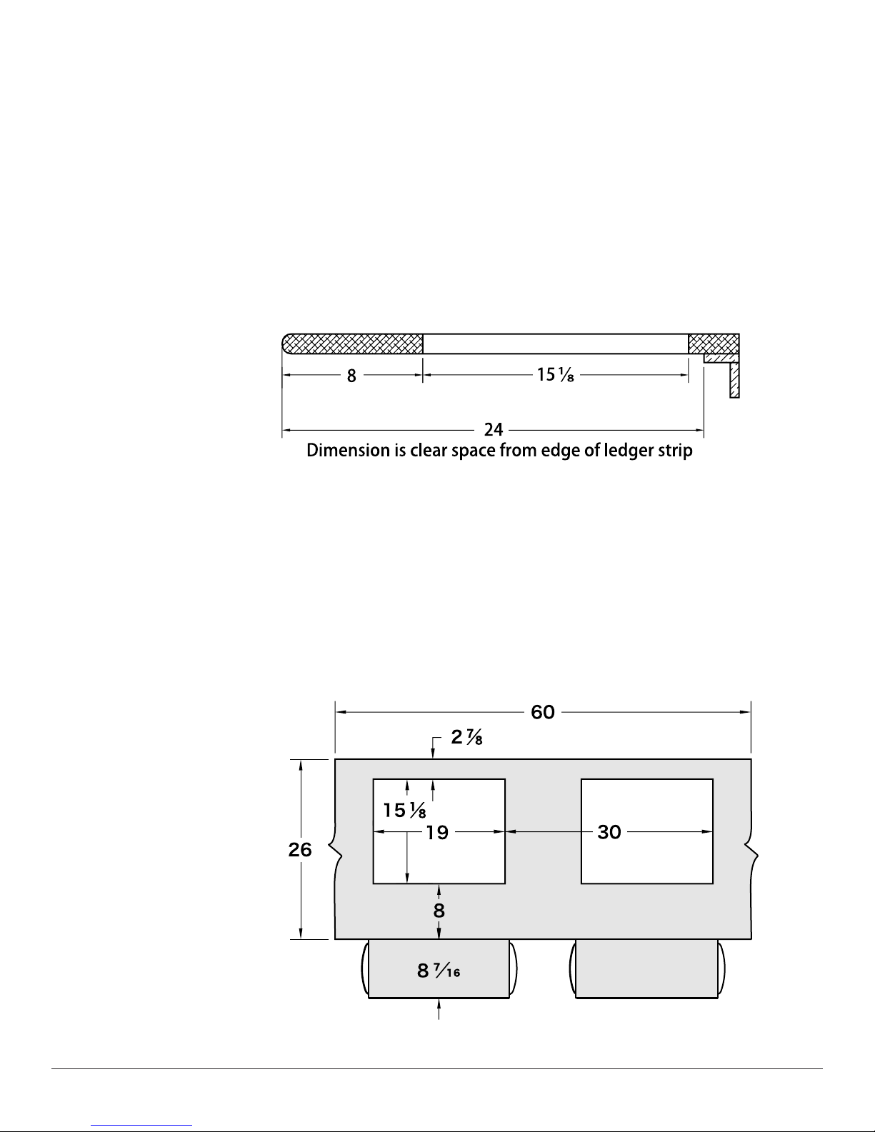
The recommended placement of the cutout f or the flipIT unit is 8 inches from the
user’s edge. This assumes a straight edge; not a round or contoured edge. If you
are experimenting with placement for an unusual application, we recommend
requesting additional templates and making dry-fit installations into scrap.
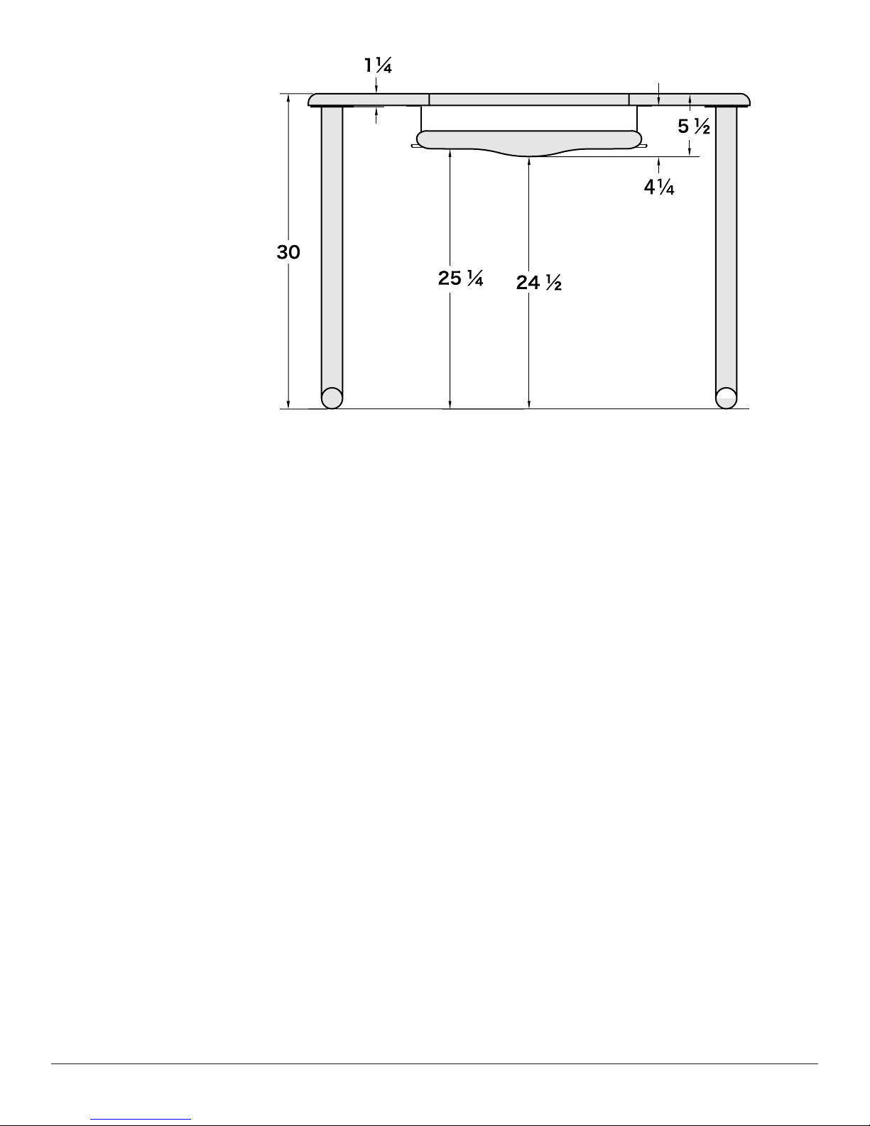
Based on this profile, a minimum of 24 inches of clearance, front to back, must be
allowed for the mechanism and LCD monitor. If you are installing modesty panels,
make sure you allow this clearance, as well.
Counter Top Depth
Workstation Spacing
Use 30 inch spacing from
centerline to centerline, or from
common reference point as shown
on the drawing (from right edge of
cut-out to right edge of cut-out).
This drawing depicts a segment of
table top and does not
indicate a minimum table top
width.
FIK/FIH-23 for widescreens
cutout is 15-5/16” x 25” and
Keyboard is 26” wide including
mouse surface.
FIK/FIH-19 for widescreens
cutout is 15-5/16” x 20.62” and
Keyboard is 26” wide including
mouse surface.

4©2009 CBT Supply Inc.
User Side Elevation
Desktop thickness may vary from no less than 3⁄4inch to 1 1⁄4inches. The suggested
position for installation of the keyboard L brackets is the 5th hole from the end, which
allows 1 11⁄16 inches keyboard clearance and the user clearances shown. The keyboard
tray assembly suspends 4 1⁄4inches from the bottom surface. A 6-foot adult male
measures 23 1⁄2inches from the top of the knee to the floor in sitting position.
Weight of LCD
Required for flipIT
to Close
For this very reason, the
pneumatic cylinder ships
partially installed.
If flipIT® is to be stored
without an LCD installed, it is
advised that the pneumatic
cylinder be disconnected for
ease of handling.
If no LCD is present, flipIT will remain open. The pneumatic cylinder is
loaded to counterbalance the weight of the LCD to open the unit. Install the LCD in
the highest position possible to achieve optimum center of gravity: 1/2” or less clear-
ance between the monitor and the lid rest flange . Several sets of holes, spaced 1/2”
apart, are provided to accommodate LCD variations. See page 14 for setting the
clearance.
Top
Support
Flange

flipIT Tech Line: 800 770-7042 5
©2009 CBT Supply Inc.
Parts and Hardware Prepare a place to unpack box contents, using a packing blanket, carpeting or
cardboard sheet to protect finished surfaces from damage. Before assembly,
take inventory of the parts included.
Parts List:
Qty 1 FlipIT Top Assembly with
grommet collar, VESA mount,
cables & pneumatic cylinder
Qty 1 Keyboard Tray Assembly
(FIK-18 only)
Qty 1 Cable release handle
(FIH-18 only)
Qty 4 Keyboard Assembly
Mounting Brackets
Qty 1 VESA LCD mounting
bracket to be installed
on LCD using your
monitor’s screws
Qty 4 Wood Screws, 3/4 inch for flipIT collar
Qty 4 Machine Screws, 1/4 in.
Qty 14 Wood Screws, 5/8 inch for Keyboard tray
& cable release
Qty 1 Paper template for top cut-out, shown positioned
for use.
Qty 1 Paper template for keyboard pilot holes, shown
positioned for use (FIK-18 only)

6©2009 CBT Supply Inc.
Step 1-
Establish Centerline
Step 2-
Adhere Cutout
Template to Desktop
To establish monitor placement, sit at the desk and look str aight ahead, visualizing
where the monitor would be. Use a tape measure and deter mine the centerline for
the monitor. Transfer the center line to the desktop with masking tape or some other
means that will not per manently mar or stain the finish.
The minimum clearance
area requirement
underneath is
24” x 24” See page 3
Counter Top Depth.
12” is the center for a 24” width.
Use a glue stick
on back of
template cut lines.
Align front edge of
template with
desktop centerline and
press in place.

flipIT Tech Line: 800 770-7042 7
©2009 CBT Supply Inc.
STEP 3 -
Drill Corner
Starting Holes
To make holes for starting your jig saw cut, use a 3/8” drill bit, place the point of the bit at the
corner mark and drill completely through the surface top. Repeat this step for each corner.
STEP 4 -
Saw the Hole for
flipIT
Place the jigsaw at the corner marking. Remove the layout line with the kerf of the saw cut for
a factory fit. You must have the skill to saw a straight line within the tolerance of the width of
the saw blade. Saw from corner hole to corner hole. Remove the remains of the paper tem-
plate when this step is finished.

8©2009 CBT Supply Inc.
Additional guide lines on template are
provided for centered alignment.
NOTE: These illustrations show the
underside of the desktop. If you can
remove the desktop for installation,
this is recommended.
STEP 6 -
Make a Depth Gauge
for Drilling Pilot Holes
STEP 7 - Drilling
Pilot Holes for
Brackets
Use a power drill to make
1/8” holes 3/8” deep using
the masking tape depth
gauge you just made.
Repeat this step for the
remaining Pilot Holes.
With this completed, the cut-out
and pilot holes should meet
factory specifications. You are
now ready to begin installation
of the flipIT mechanism.
STEP 5 -
Positioning Template
for Keyboard Tray
Pilot Holes
Use a glue stick on the back of the template where holes are indicated to be dr illed.
Press the template in place, aligning centerline at front edge of desktop.
To help prevent the mistake of
drilling though your desktop, use
a depth gauge, or make one
with masking tape. Measure
3/8” from the tip of the 1/8” drill
bit to indicate the dr illing depth
for mounting bracket pilot holes.
Mark the 3/8” depth with a piece
of masking tape wrapped
around the drill bit.

flipIT Tech Line: 800 770-7042 9
©2009 CBT Supply Inc.
STEP 8 –
Install FlipIT Top &
Collar Assembly
into desktop
Installation Tip
To protect finished surfaces,
select a carpeted assembly
area, or place a packing
blanket or sheet of cardboard
on the floor.
Place the FlipIT top assembly into the desktop precut opening. You may need to flex
the edge of the collar to per mit the assembly to seat properly. You may note that
there is a larger gap between the lid and collar on the side f acing the back edge. This
extra clearance is normal.
Using #2 Phillips
screwdriver bit,
install four 3⁄4inch
wood screws in the
locations shown in
the two sides of the
assembly.
Using an 1⁄8inch bit, drill pilot holes
taking care to position the dr ill
squarely.

10 ©2009 CBT Supply Inc.
FIH Model:
Install Cable Release
If you are installing the FIH flipIT
Kit with no keyboard tray, the
template for pilot holes to install
a keyboard tray is not included.
There is no template for cable
release pilot holes. You will use
the cable release assembly itself
to determine pilot hole locations.
The screw and locking nut ships installed on the lid ar m. Remove the locking nut,
place the cable release eyelet over the screw with the cable side of the fitting facing
away from the lid arm. Replace the locking nut. Tighten the nut, then back it off a
quarter turn so it moves freely.
To mark locations for drilling 5 pilot holes, pull the slack out of the cable and place
the bracket parallel with the lid. Mark hole locations with pencil.
Using 1/8” bit, drill pilot holes
using masking tape for a
depth gauge. With 5 wood
screws, install the handle
bracket.
Installation tip:
If you are also installing a
3rd-party keyboard tray,
install that hardware before
installing the flipIT handle so
you can make adjustments
for handle placement.
Do not drill through the desk-
top! Use a depth gauge or
make one out of masking
tape. See page 8 Drilling
Pilot Holes.

flipIT Tech Line: 800 770-7042 11
©2009 CBT Supply Inc.
Step 9 –
Attach L Brackets to
Keyboard Tray
Assembly
Step 10 –
Install Keyboard Tray
Step 11 –
Connect Cables to
Keyboard Tray
Assembly
Locate the 5th hole from the end in the
Keyboard Mounting Bracket, and secure it
to the tapped hole in the Keyboard Tray
Assembly using a 1⁄4inch machine screw.
Repeat this step in four places
The suggested location provides
1 3⁄4inches of clearance to fit
most keyboards. Measure the
thickness of your keyboard and
choose a different hole to
accommodate a thicker key-
board. 1 3⁄4inches is the mini-
mum clearance
Using 8 of the 5/8 inch w ood screws, install the key-
board tray’s L brackets to the under side of the desk-
top, into the pilot holes dr illed, using a #2 Phillips
screw driver bit.
Cables link the lid to the k ey-
board tray. Thread the cable
end through a slot in the k ey-
board tray that aligns well with
the assembly. Slide pin though
cable end.
Cables may have a
little slack when
properly installed.

12 ©2009 CBT Supply Inc.
Step 12 –
Connect Pneumatic
Cylinder
Step 13 –
Mount Your LCD
Monitor
flipIT won’t close
without an LCD
installed
The pneumatic cylinder ships attached to the mounting post of the flipIT lid with loc king hubs
installed. Use a slotted screwdriver to pry off the locking hubs to the distance sho wn below.
The VESA mount is a 2-par t assembly.
The male part is installed on the flipIT
lid (right) with 5mm Euro screws. The
female half installs on your LCD using
the screws from your LCD.
Capture the mounting peg, located on the collar , with the cylinder’s fitting. First press against
the connector rod until the fitting seats , then press the locking hub in.

flipIT Tech Line: 800 770-7042 13
©2009 CBT Supply Inc.
Attach VESA Bracket
to LCD Display
Remove the screws
installed in the LCD and
use them to install the
VESA Bracket with the
flanges angled wider
toward the base of the
display. Secure all four
screws into the corre-
sponding holes in the
VESA Bracket.
All VESA FDMI LCD dis-
plays are shipped from
the manufacturer with
mounting screws installed.
The locations of these
screws are either 75mm
or 100mm between cen-
ters. These holes may be
immediately visible,
capped, or accessible by
removing the monitor
stand or a rear cover plate
on the back of the moni-
tor. The predrilled holes in
the VESA Mounting
Bracket can be used with
either configuration.
Installation Tip:
Place a blanket in your
assembly area so you can
protect your LCD screen
and fine furniture surfaces.
In some cases, a conversion package may be required. Contact your monitor manufacturer for additional information.
The VESA mount conversion kit from Apple is used f or installing the Apple® 24 HD Cinema Display, for example.
Purchase this kit from the Apple w eb site. Go to the Apple Store and search the ter m VESA adapter.
The iMac® products’ drive location does not per mit use with flipIT.

14 ©2009 CBT Supply Inc.
STEP 14 —
Connect Cables
IMPORTANT NOTE:
When handling your LCD display,
take care to protect the screen
from damage by placing packing
blankets on work surfaces.
Place the display on a
protected surface to
keep it from being
damaged as shown.
Make cable connec-
tions and route them
through the flipIT top,
ready for complete
connection later.
STEP 15 —
Attach LCD Display
to flipIT Top
Grasp the LCD with both hands and capture the mounting surf ace. Gravity will hold the LCD
in place. When the flipIT closes, a gravity pin will keep the mounting device nested.
Additional sets of mounting holes,
set 1/2” apart, are provided to
achieve the ideal position.
The VESA mount ships installed in the set of mounting holes one step lo wer than the top. If
you measure more than 1/2” clearance between the monitor and the lid suppor t flange, use the
top set of mounting holes to put it in the correct r ange. If the monitor does not clear the flange ,
choose a lower set.
If you experience a problem keeping the lid closed with the monitor mounted as descr ibed,
your monitor may be lighter weight than expected. A less powerful pneumatic cylinder may
solve this problem. Contact CBT Supply.
Check your clearances
Your LCD monitor should be
installed as high on the lid as
possible, with clearance of
1/2” or less between lid sup-
port flange and monitor.
Achieving this position is impor-
tant so the center of gravity is
correct to keep the flipIT lid
closed.
Move
down 1
notch.
Move
up 1
notch.
Space =
1/2” or
less
RIGHT WRONGWRONG

flipIT Tech Line: 800 770-7042 15
©2009 CBT Supply Inc.
STEP 18 -
Test the Flipit Top
Parts List
You can actuate the flipIT rotation either b y pulling
out the keyboard tray about an inch, by using the
cable release (FIH model), or by depressing the
back of the flipIT desktop. The pneumatic cylinder
will do all of the work.
The keyboard tray works independently in all
other respects on Generation II.
The flipIT desktop is closed by manually
closing it like a lid.
The hinge of the VESA mount on Generation II
allows adjustment of the screen angle . You may
adjust the LCD screen angle by squeezing the top
of the display and the flipIT lid for a laid-back
angle, or push on on the bottom of the displa y for
a steep angle.
Item No. Qty. Part Number Title
1 1 27909 Frame
2 2 27332 Bushing
3 1 27901 RH Arm Assembly
4 1 27902 LH Arm Catch Assembly
5 1 27919 Pneumatic Cylinder
6 1 27898 Keyboard Tray / Slide Assembly (FIK only)
7 1 27892 Flat Screen Tilt Assembly
8 1 27884 Bracket / Screw Package
9 1 28193 Top Lid
10 3 28163 Euro Screw
2
1
3
4
5
6
7
8
9
10

16 ©2009 CBT Supply Inc.
CBT Supply, Inc.’s patented flipIT®Integrated LCD Workstation has been designed
and tested to perform as an ergonomically correct, space sa ving unit.
For more information on this and other flipIT ®products,
call 1-800-770-7042
Parts Identification
GENERATION I I
Hardware store specifications for screws and nuts.
US Patent Pending
#10 x 5/8 Round Head
Wood Screw (21486) (8)
This manual suits for next models
5
Table of contents
Other CBT Supply Indoor Furnishing manuals
Popular Indoor Furnishing manuals by other brands

Allen + Roth
Allen + Roth NORRIS 30RAL installation manual

pakoworld
pakoworld GAME 119-000905 manual

Costway
Costway NP10896 manual

World Market
World Market Netanya 597165 Assembly instructions

American Standard
American Standard Antiquity 1.6 GPF One-Piece Toilet 2038.016 installation instructions

HJH office
HJH office SPEKTRE Assembly instructions

ATIM
ATIM SHOT 411/78.1130.25 Assembly instructions

VONDOM
VONDOM FAZ 54166 Assembly instructions

Opitec
Opitec EasyLine Trivet quick start guide

Habitat
Habitat Rosella Ottoman 890/4689 quick start guide

Wildridge
Wildridge LCC-153 Assembly instructions

Amart Furniture
Amart Furniture CONNELLAN 67428 Assembly instruction