CBT Supply SFI-363030-TKF User manual

cCBT Supply Inc. FIip-it Series Page 1
SFI Single Workstations
Left End Panel (1 ea.) Right End Panel (1 ea.)
Front Edge
Front Edge
Back Panel (1 ea.)
Front Edge
CPU Bottom (1 ea.)
= Cam Fitting
= Cam Hole
= Screw Hole/Spoon Pin
= RV Fitting
= Grommet/wire access
Keyboard/Hinge Mechanism (1ea.)
Comes attached to Top
Support Panel (1 ea.)
Panel List
models listed below
Note: Separate and stack panels by like types before beginning assembly process.
1 Desktop Panel • 1 Back Panel • 1 Left End Panel • 1 Right End Panel • 1 Support Panel
1 Keyboard/Hinge Mechanism • 1 CPU Bottom
Desktop Panel (1 ea.)
See flipIT LCD Monitor Installation Instructions for securing of LCD Flat Display * to flipITTM Rotating Desktop Panel

The Smartdesk is packaged ready to be assembled. Included is a Master Parts and Panel List showing diagrams of all parts
and hardware required for assembly. Please note, improper installation may void Smartdesk warranty. To install correctly
follow the enclosed instructions. If you need additional assistance or information please contact Technical Service at 410-
922-6005 or email [email protected] or call 866-620-7408. cCopyright Smartdesks ltd. 2002.All rights reserved.
Smartdesks FI Single Workstations
Unpack Parts and Hardware:
Parts and panels will vary according to Smartdesks model. See Parts & Panels List and Hardware Inventory Sheet.
Please verify all parts and quantities prior to assembly. Contact the factory if your quantities are incomplete.
Note: All panels are predrilled ready for assembly.
Note:Keyboard/Hinge Mechanism comes preassembled on pull-out hinge attached to Desktop.
NOTE: DO NOT CUT THE NYLON CABLE TIE FROM THE KEYBOARD HINGE UNTIL THE DESK IS ASSEMBLED AND UPRIGHT.
Tools needed for assembly:
Power drill with #2 Phillips screwdriver bit and regular #2 Phillips screwdriver.
The following diagram shows the contents of the hardware bag.
Contents of Hardware Bag: (quantities for each unit - multiply by number of components)
SFI Single Workstations Flip-it Single Series Page 2
cCBT Supply Inc.
14 ea. - Cam Pins
push through holes in panels,
(Side Panels, Back Panels,
Support Panels, CPU Bottom)
1 ea. - Wire Trough
black PVC used to contain
wiring inside rear of
Back Panel
See flipIT LCD Monitor Installation Instructions for securing of LCD Flat Display * to flipITTM Rotating Desktop Panel
SFI-363030-TKF
SFI-443030-TKF
SFI-483030-CKF
SFI-603030-CKF
SFI-723030-CKF

STEP 1 - Desk Panel & Side PanelAssembly
NOTE: 1 person assembly required for proper fit.
NOTE: DO NOT CUT THE NYLON CABLE TIE FROM THE KEYBOARD
HINGE UNTIL THE DESK IS ASSEMBLED AND UPRIGHT.
In a clean work area lay Desk Top Panel facing down on
the floor on cardboard or carpet/packing quilt. (Fig. 1)
Lift and place Right Side Panel into 90overtical position
with fittings facing in. While holding right panel in vertical
position, match RV Fittings to one another and snap
panel into place. Use power drillto tighten the screw
contained in the RV Fitting. (Fig.2) Each RV Fitting
contains a screw to lock the hardware once the panels
have been snapped into place. Warranty is void if all
locking screws have not been tightened. RV Fittings
come preinstalled in panels and are equally spaced along
Desk Top edge. Tighten all remaining RV Fittings along
panel edge. (Fig.3)
Repeat STEP 1 for the installation of the Left Side Panel.
STEP 2 - Back Panel To Sides Assembly
NOTE: 2 person assembly required for proper fit.
Slide Back Panel into position between two Side Panels
matching the cam fittings to the holes at top. It is necessary
for 2 people to accomplish this assembly. Vertical panels
cannot be left standing unsupported (Fig.4) Insert top
2 Cam Pins through Left and Right End Panels into cam
fittings. (Fig. 5) Start at the top cam of each end panel
when inserting Cam Pins and move down each end
panel alternating as Cam Pins are inserted. Make sure
arrows on Cam Pins are facing out (3 pm clock position).
Tighten about 1/4 turn with screwdriver until it locks into
place.(Fig. 6) Repeat this step for remaining 4 Cam
Pins. The Cam Pin is a steel to steel assembly which
ensures heavy duty strength when assembled.
Figure 1
Figure 2
Figure 3 Check to verify that arrow is
pointing perpendicular to pin
when cam is locked.
Figure 4
Figure 5
cCBT Supply Inc.
Cam pin is inserted through
panel into preinstalled fitting.
(Once Back Panel is secured to Left
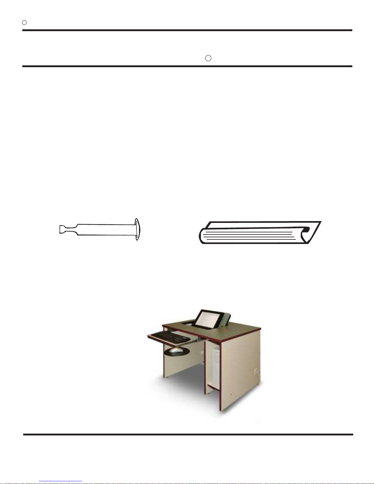
and Right Side Panels, the “shell” of
the desk is assembled. See Figure 7
on next page)
Figure 6
SFI Single Workstations Flip-it Single Series Page 3

Figure 7 Smartdesks Flip-it Series Single Station with
Back & Side Panels assembled.
STEP 3 - Center Support Panel (CPU)
Cabinet Assembly
NOTE: 1 person assembly required for proper fit.
Hold Center Support Panel in 90overtical position with
the corner notch facing away from Back Panel. (This
allowance is for the Keyboard/Hinge Mechanism.) Match
RV Fittings to one another and snap panel into place.
Use power drill to tighten the screw contained in the RV
Fitting. (Fig. 8) Cam Pin holes in Back Panel should
align with Cams in Center Support Panel. Insert Cam
Pin through back panel into cam fitting. (Fig. 9) You
may have to flex Back Panel up and down slightly to get
Cam Pin to slide into hole. Tighten with screwdriver until
it locks into place. Check to verify that the arrow is facing
out. Repeat this step for remaining Cam Pin. The Center
Support Panel is now locked into position.
If ordered a model with 2 Center Support Panels, repeat
STEP 3 for the installation of remaining support panel.
STEP 4 - Installation of CPU Bottom
NOTE: 1 person assembly required for proper fit.
The CPU Bottom is not adjustable. Make sure arrows
on Cams are facing out. Slide the CPU bottom into
position. (Fig10) Aligning the CPU Bottom with the
predrilled holes, insert Cam Pin through the CPU Side
Panel into cam fitting. Tighten with screwdriver until it
locks into place. Repeat this step for remaining 3 Cam
Pins. (Fig. 11)
cCBT Supply Inc.
Figure 7
Figure 9
Figure 10
Figure 8
Cam pin is inserted through
panel into preinstalled fitting.
Check to verify that arrow is pointing
perpendicular to pin when cam is locked.
Figure 11
SFI Single Workstations Flip-it Single Series Page 4

STEP 6 - Flip Desk 180oto Upright Position
Note: 2 persons required for this step.
Roll desk on to its back then to upright position.
NOTE: CUT THE NYLON CABLE TIE FROM THE KEYBOARD
HINGE AFTER THE DESK IS ASSEMBLED AND UPRIGHT.
STEP 7 - Installation of Wire Trough
Once computer and wiring is installed, the black PVC
Wire Trough can be used to neatly contain wiring. Position
black plastic Wire Trough near grommet in Side Panel
and near notches at Center Panel. Hold Wire Trough
approx. 1” up from bottom of Back Panel in line with
gromets and scallops on dividers. Peel off PSA tape on
rear of Wire Trough and stick to inside rear of Back Panel.
cCBT Supply Inc.
Smartdesks have been designed and tested as an
ergonomically correct and space saving unit. For more
information on this and other Smartdesks products,
call 1-800-770-7042 or visit our website at
http://www.smartdesks.com
Smartdesks Model SFI-363030-TKF
See flipIT LCD Monitor Installation Instructions for securing
of LCD Flat Display * to flipITTM Rotating Desktop Panel
SFI Single Workstations Flip-it Single Series Page 5
Other CBT Supply Indoor Furnishing manuals
Popular Indoor Furnishing manuals by other brands

Home affaire
Home affaire Konrad 680000 Assembly instructions

Keter
Keter OXFORD Assembly instructions

Riverside Furniture
Riverside Furniture Joelle Aassembly Instructions

Naomi Kids
Naomi Kids Doll Armoire Assembly instructions

New Classic Furniture
New Classic Furniture DOMINGO B5902-110 Assembly instructions

Furniture of America
Furniture of America CM-BK931-TT Assembly instructions

Baxton Studio
Baxton Studio Bed MG8005 Assembly instructions

Belleze
Belleze Bistro 014-HG-20062 Assembly instructions

Argos Home
Argos Home New Hallingford 652/9482 Assembly instructions

Sorelle
Sorelle Farmhouse Room Assembly instruction

Songmics
Songmics VASAGLE LET311 Assembly instructions

Astonica
Astonica 50101016 instruction manual