CCL ELECTRONICS C6082A User manual

2
This device complies with Part 15 of the FCC Rules. Operation is subject to the following two
conditions: (1) this device may not cause harmful interference, and (2) this device must accept
any interference received, including interference that may cause undesired operation.
Warning: Changes or modications to this unit not expressly approved by the party responsible
for compliance could void the user’s authority to operate the equipment.
NOTE: This equipment has been tested and found to comply with the limits for a Class B digital
device, pursuant to Part 15 of the FCC Rules. These limits are designed to provide reasonable
protection against harmful interference in a residential installation. This equipment generates,
uses and can radiate radio frequency energy and, if not installed and used in accordance with
the instructions, may cause harmful interference to radio communications.
However, there is no guarantee that interference will not occur in a particular installation. If
this equipment does cause harmful interference to radio or television reception, which can be
determined by turning the equipment o and on, the user is encouraged to try to correct the
interference by one or more of the following measures:
- Reorient or relocate the receiving antenna.
- Increase the separation between the equipment and receiver.
- Connect the equipment into an outlet on a circuit dierent from that to which the receiver is
connected.
- Consult the dealer or an experienced radio/TV technician for help.
“ FCC RF Radiation Exposure Statement
Caution: To maintain compliance with the FCC’s RF exposure guidelines, place the unit at least
20cm from nearby persons.”

3
TABLE OF CONTENTS
PRECAUTIONS . . . . . . . . . . . . . . . . . . . . . . . . . . . . . . . . . . . . . . . . . . . . . .2
INTRODUCTION . . . . . . . . . . . . . . . . . . . . . . . . . . . . . . . . . . . . . . . . . . . . . . 3
OVERVIEW . . . . . . . . . . . . . . . . . . . . . . . . . . . . . . . . . . . . . . . . . . . . . . . . . 4
CONSOLE . . . . . . . . . . . . . . . . . . . . . . . . . . . . . . . . . . . . . . . . . . . . . . . 4
LCD DISPLAY . . . . . . . . . . . . . . . . . . . . . . . . . . . . . . . . . . . . . . . . . . . . . 4
WIRELESS THERMO-HYGRO SENSOR . . . . . . . . . . . . . . . . . . . . . . . . . . . . . . 5
INSTALLATION AND SETUP . . . . . . . . . . . . . . . . . . . . . . . . . . . . . . . . . . . . . . .5
INSTALL WIRELESS THERMO-HYGRO SENSOR . . . . . . . . . . . . . . . . . . . . . . . . . 6
SETUP THE CONSOLE . . . . . . . . . . . . . . . . . . . . . . . . . . . . . . . . . . . . . . . . 6
ADDITIONAL WIRELESS SENSOR(S) (OPTIONAL) . . . . . . . . . . . . . . . . . . . . . . . . 7
SMART LIFE APP . . . . . . . . . . . . . . . . . . . . . . . . . . . . . . . . . . . . . . . . . . . . .7
ACCOUNT REGISTRATION . . . . . . . . . . . . . . . . . . . . . . . . . . . . . . . . . . . . . 7
CONNECT WEATHER STATION TO WIFI NET WORK . . . . . . . . . . . . . . . . . . . . . . . 7
DEVICE SCREEN OVERVIEW . . . . . . . . . . . . . . . . . . . . . . . . . . . . . . . . . . . . 9
TO VIEW HISTORY GRAPH . . . . . . . . . . . . . . . . . . . . . . . . . . . . . . . . . . . . . 9
TO SET ALERT NOTIFICATION . . . . . . . . . . . . . . . . . . . . . . . . . . . . . . . . . . 10
AUTOMATION WITH OTHER DEVICE USING SMART LIFE. . . . . . . . . . . . . . . . . . . 10
IOT APPLICATION . . . . . . . . . . . . . . . . . . . . . . . . . . . . . . . . . . . . . . . . . . 11
OTHER FEATURE IN SMART LIFE APP . . . . . . . . . . . . . . . . . . . . . . . . . . . . . . 11
FIRMWARE UPDATE . . . . . . . . . . . . . . . . . . . . . . . . . . . . . . . . . . . . . . . . 12
OTHER SETTING & FUNCTIONS OF THE CONSOLE . . . . . . . . . . . . . . . . . . . . . . . . 12
MANUAL CLOCK SETTING . . . . . . . . . . . . . . . . . . . . . . . . . . . . . . . . . . . . . 12
SETTING ALARM TIME . . . . . . . . . . . . . . . . . . . . . . . . . . . . . . . . . . . . . . . 12
ACTIVATING ALARM FUNCTION . . . . . . . . . . . . . . . . . . . . . . . . . . . . . . . . . 13
WIRELESS SENSOR SIGNAL RECEIVING . . . . . . . . . . . . . . . . . . . . . . . . . . . . 13
TEMPERATURE / HUMIDITY FUNCTION . . . . . . . . . . . . . . . . . . . . . . . . . . . . . 13
TO VIEW MAX / MIN . . . . . . . . . . . . . . . . . . . . . . . . . . . . . . . . . . . . . . . . . 14
CALIBRATION . . . . . . . . . . . . . . . . . . . . . . . . . . . . . . . . . . . . . . . . . . . . 14
BACK LIGHT . . . . . . . . . . . . . . . . . . . . . . . . . . . . . . . . . . . . . . . . . . . . . 14
SET LCD DISPLAY CONTRAST . . . . . . . . . . . . . . . . . . . . . . . . . . . . . . . . . . 15
MAINTENANCE . . . . . . . . . . . . . . . . . . . . . . . . . . . . . . . . . . . . . . . . . . . . . 15
BATTERY REPLACEMENT . . . . . . . . . . . . . . . . . . . . . . . . . . . . . . . . . . . . . 15
TROUBLESHOOT . . . . . . . . . . . . . . . . . . . . . . . . . . . . . . . . . . . . . . . . . . 15
SPECIFICATION . . . . . . . . . . . . . . . . . . . . . . . . . . . . . . . . . . . . . . . . . . . . . 15
CONSOLE . . . . . . . . . . . . . . . . . . . . . . . . . . . . . . . . . . . . . . . . . . . . . . 15
WIRELESS THERMO-HYGRO SENSOR . . . . . . . . . . . . . . . . . . . . . . . . . . . . . 16
ABOUT THIS USER’S MANUAL
This symbol represents a warning. To ensure safe use, always adhere to the
instructions described in this documentation.
This symbol is followed by a user’s tip.
PRECAUTIONS
- Keeping and reading the “User manual” is highly recommended. The manufacturer and supplier
cannot accept any responsibility for any incorrect readings, export data lost and any consequences
that occur should an inaccurate reading take place.
- Images shown in this manual may dier from the actual display.
- The contents of this manual may not be reproduced without the permission of the manufacturer.
- Technical specications and user manual contents for this product are subject to change without
notice.
- This product is not to be used for medical purposes or for public information

4
- Do not subject the unit to excessive force, shock, dust, temperature or humidity.
- Do not cover the ventilation holes with any items such as newspapers, curtains etc.
- Do not immerse the unit in water. If you spill liquid over it, dry it immediately with a soft, lint-free
cloth.
- Do not clean the unit with abrasive or corrosive materials.
- Do not tamper with the unit’s internal components. This invalidates the warranty.
- Placement of this product on certain types of wood may result in damage to its nishing for which
manufacturer will not be responsible. Consult the furniture manufacturer’s care instructions for
information.
- Only use attachments / accessories specied by the manufacturer.
- This product is intended for use only with the adaptor provided: Manufacturer: HUAXU Electronics
Factory, Model: HX075-0501000-AB, HX075-0501000-AG-001 or HX075-0501000-AX.
- The socket-outlet shall be installed near the equipment and easily be accessible.
- When replacement parts are required, be sure the service technician uses replacement parts
specied by the manufacturer that have the same characteristics as the original parts. Unauthorized
substitutions may result in re, electric shock, or other hazards.
- This product is not a toy. Keep out of reach of children.
- The console is intended to be used only indoors.
- Place the console at least 20cm from nearby persons.
- This device is only suitable for mounting at height < 2m.
- When disposing of this product, ensure it is collected separately for special treatment.
- CAUTION! Risk of explosion if battery is replaced by an incorrect type.
- Battery cannot be subjected to high or low extreme temperatures, low air pressure at high
altitude during use, storage or transportation, if not, it may result in an explosion or the leakage of
ammable liquid or gas.
- Disposal of a battery into re or a hot oven, or mechanically crushing or cutting of a battery, that
can result in an explosion.
- Do not ingest the battery, Chemical Burn Hazard.
- This product contains a coin/button cell battery. If the coin/button cell battery is swallowed, it can
cause severe internal burns in just 2 hours and can lead to death.
- Keep new and used batteries away from children.
- If the battery compartment does not close securely, stop using the product and keep it away from
children.
- If you think batteries might have been swallowed or placed inside any part of the body, seek
immediate medical attention.
- Only use fresh batteries. Do not mix new and old batteries.
- Dispose of used batteries according to the instructions.
- Replacement of a battery with an incorrect type that can result in an explosion or the leakage of
ammable liquid or gas.
INTRODUCTION
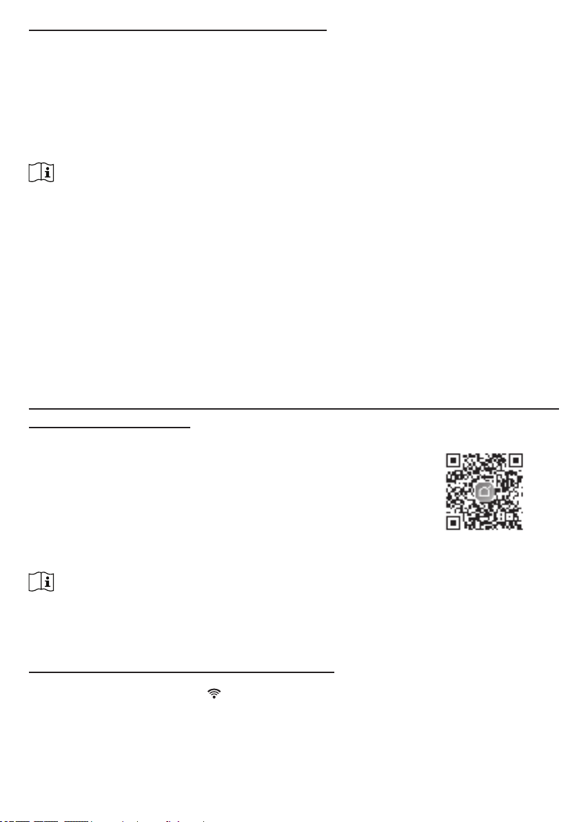
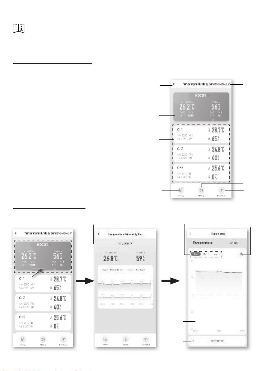
Thank you for selecting SMART multi-channel weather station. The console has WiFi module
built-in and through its smart system is compatible with Tuya IOT platform. Through the Smart
Life App, you can view the temperature and humidity of main console and wireless sensor(s),
check history records, set high / low alarm and trigger tasks in anywhere.
This system come with a wireless thermo-hygro sensor and can support up to 7 additional
sensors(optional). User can monitor and set multi trigger task to control other Tuya compatible
device(s) according to the specic condition(s).
The colorful LCD display shows the readings clearly and tidy, this system is a truly IoT system
for you and your home.
NOTE:
This instruction manual contains useful information on the proper use and care of this product.
Please read this manual through to fully understand and enjoy its features, and keep it handy
for future use.

5
OVERVIEW
CONSOLE
13
12
11
14
15
16
2
3
4
5
8
7
6
9
10
1
1. [ ALARM/SNOOZE ] key
2. LCD display
3. [ CHANNEL / + ] key
4. [ MODE / ALARM ] key
5. [ MAX / MIN / - ] key
6. [ HI / LO ] slide switch
7. [ / CAL ] key
8. [ TIME SET ] key
9. Table stand
10. Battery door
11. Wall mounting hole
12. [ °C / °F ] key
13. [ Refresh ] key
14. [ RESET ] key
15. [ SENSOR / WI-FI ] key
16. Power jack
LCD DISPLAY
1. Time & Date
2. Temperature & humidity
3. Indoor temperature & humidity
1
2
3

6
WIRELESS THERMO-HYGRO SENSOR
1. LED indicator
2. Wall mounting holder
3. Channel slide switch
4. [ RESET ] key
5. Battery compartment
1 2
3
4
5
INSTALLATION AND SETUP
INSTALL WIRELESS THERMO-HYGRO SENSOR
1. Remove the battery door of the sensor.
2. Use the channel slide switch to set the channel number for the
sensor (e.g. Channel 1)
3. Insert 2 x AA size batteries into the battery compartment according
to the polarity marked on the battery compartment, and close the
battery door.
4. The sensor is in synchronization mode, and can be registered to the
console within the next few minutes. The transmission status LED
will begin to ash every 1 minute.
NOTE:
- If you need to re-assign the sensor channel, slide the channel slide switch to the new channel
position and press [ RESET ] key on the sensor for the new channel number to be eective.
- Avoid placing the sensors in direct sunlight, rain or snow.
- To avoid the sensor/s and console pairing failure during new console setup, please power up the
sensor(s) rst, and then press [ SENSOR/WiFi ] key on the main unit.
PLACING THE WIRELESS THERMO-HYGRO SENSOR
Place a screw on the wall that you wish to hang the sensor on.
Hang the sensor onto the screw by the wall mounting holder. You
can also place the sensor on a table by itself.

7
SETUP THE CONSOLE
INSTALL THE BACKUP BATTERY
Backup battery provides power to the console to retain clock time and date, max/min records
and calibration value.
Step 1 Step 2 Step 3
Remove the console
battery door with coin
Insert a new CR2032
button cell battery
Replace the battery door.
NOTE:
- The backup battery can back up: Time & Date, Max/Min records and calibration value.
- The built-in memory can back up: Router setting server settings.
- Please always remove the back-up battery if the device is not going to be used for a while. Please
keep in mind that even when the device is not in use, certain settings, such as the clock, calibration
and records in its memory, will still drain the back-up battery.
POWER UP THE CONSOLE
1. Plug in the power adapter to power up the console.
2. Once the console is power up, all the segments of the LCD will be shown.
3. The console will automatically enter AP mode and sensor synchronization mode
automatically.
Blinking:
Trying to connect to router
Stable:
Connected to router
Stable:
Connected to router and
synchronized to local time
Flashing:
Console currently in Access
Point (AP) mode
Blinking:
Sensor synchronization
process
4.The wireless sensor will automatically pair up with console (about 1 minute). Upon successful
synchronization, display will change from "--.-°C --%" to actual reading.
NOTE:
If no display appears when power up the console. You can press [ RESET ] key by using a pointed
object. If this process still not work, you can remove the backup battery and unplug the adaptor then
re-power up the console again.
RESET AND FACTORY HARD RESET
To reset the console and start again, press the [ RESET ] key once or remove the backup battery
and then unplug the adapter. To resume factory settings and remove all data, press and hold the
[ RESET ] key for 6 seconds.
CHANGING BATTERIES AND MANUAL PAIRING OF SENSOR
Whenever you changed the batteries of the wireless sensor, re-synchronization must be done
manually.
1. Change all the batteries to new ones in the sensor.
2. Press [ SENSOR / WI-FI ] key on the console to enter sensor Synchronization mode.
3. Console will re-register the sensor after its batteries are changed (about 1 minute).

8
ADDITIONAL WIRELESS SENSOR(S) (OPTIONAL)
The console can support up to 7 wireless sensors.
1. In the new wireless sensor, slide the Channel switch to a new CH number
2. Press the [ RESET ] key on the new sensor.
3. At the back of the console, press the [ SENSOR / WI-FI ] key enter sensor synchronization
mode
4. Wait for the new sensor(s) to pair up with the console. (about 1 minute)
5. Once the new sensor(s) are connected to the console successfully, their temperature and
humidity will be shown accordingly.
NOTE:
- Channel number of the sensor must not be duplicated among the sensors. Please refer to “INSTALL
Wireless thermo-hygro SENSOR” for details
- This console can support dierent type of additional wireless sensor(s), e.g. soil moisture. If you
would like to pair up additional sensors, please check with your retailer for more detail.
SENSOR(S) RESYNCHRONIZATION
Press the [ SENSOR / WI-FI ] key once for the console to enter sensor Synchronization mode
(channel number blinking), and the console will re-register all the sensors that have already
been paired to it before.
REMOVE WIRELESS SENSOR
User may manually delete any sensor from the console.
1. Press the [ CHANNEL ] key until the console shows the display of the selected sensor.
2. Press and hold [ REFRESH ] key for 10 seconds, until its readings are reset " -- , -°C -- % "
is shown.
SMART LIFE APP
ACCOUNT REGISTRATION
The console works with Smart Life App for Android and iOS smart phone.
1. Scan the QR code to go to the Smart Life download page
2. Download Smart Life from Google Play or Apple App store.
3. Install the Smart Life App.
4. Follow the instruction to create your own account using phone
number or email.
5. Once the account registration is completed, the Home Screen
will be shown. Smart Life for
Andriod /IPhone
NOTE:
- There is no Registration code needed if email method is chosen.
- The App may be subject to change without notice.
- You may be prompted to allow the App to have access to your location. This will allow the app to give you
general weather information in your area. The app will still work if you don' t allow access to that.
CONNECT WEATHER STATION TO WIFI NETWORK
1. Press and hold the [ SENSOR / WI-FI ] key for 6 seconds to enter AP mode manually,
indicated by blinking AP and . When the console is power up for the rst time, the console
will automatically enter and stay at AP mode.
2. Open Smart Life App and follow the in-app instructions to connect weather station to your
Wi-Fi network.

9
Step 1:
At the home screen , tap the on the
top right corner to add your console.
Step 5:
There will auto scan and register
your device.
Step 6:
Once it success, the console icon will shown,
and you can customize its information.
Step 4:
Con rm your device is in "AP mode" and
tap "Next".
Step 3:
Make sure you select the 2.4G network
and enter your Wi-Fi password then tap
the "Next".
Step 7:
The console will appears on your Home
Screen. Tap to see the readings.
Step 2:
On "Add Manually" screen, choose
"Sensors" in the left menu bar and
then select "Temperature and Humidity
Sensor(Wi-Fi)".

10
3. The console will automatically exit AP mode and return to normal operation once it's connected
to Wi-Fi router.
NOTE :
- Smart weather station can only connect to 2.4G WI-FI network
- Enable the location information in your mobile when you add your console to App.
- User may press and hold [ SENSOR / WI-FI ] for 6 seconds to exit AP mode any time.
DEVICE SCREEN OVERVIEW
The device screen can show the IN and (CH) Channel's readings, max / min records, and
access to graphs, alert setting, alert history and unit conversion.
1. Temperature and humidity reading with max/min
records for INDOOR
2. Temperature and humidity reading with max/min
records for wireless sensor (CH1 - CH7)
3. Back to home page icon
4. Device management for advance feature and
rmware update
5. View the alert history
6. Setting for alert noti cation
7. Change temperature unit
34
57
6
2
1
TO VIEW HISTORY GRAPH
You can view the history graph by tapping the INDOOR or CH region in "device page".
Select the period Download
data by email
History graph
Select date
Hourly graph,
tap to view
"data curve"
page
Select IN or other CH graph

11
TO SET ALERT NOTIFICATION
You can set the temperature and humidity high / low alarm.
Step 1:
Tap the "Setting" on the bottom of the
"device Screen".
Step 2:
Tap the "Temperature Alarm" or
"Humidity Alarm".
Step 3:
Tap the "INDOOR" or "CH 1 ~ 7 ".
Step 4:
Set the High / Low trigger values and
slide the switch to activate the alert.
AUTOMATION WITH OTHER DEVICE USING SMART LIFE
Smart Life
Console
Wireless Sensor (s)
Smart Switch Devices
Heater BulbsFans
Humidifier Dehumidifier
Smart Sockets

12
IOT APPLICATIONS
Through the Smart life App, you can create the temperature and humidity trigger conditions to
control other Smart Life compatible device(s) automatically.
Step 1:
Tap the " Smart" icon on Home
screen, and follow the instruction
to set condition and task..
Step 2:
Tap the " " icon.
Step 3:
Tap one of below tag to set di erent
trigger condition.
NOTE :
-Any tasks required or performed by third party devices are at user's own choice and risk.
-Please note no guarantee can be assumed regarding the correctness, accuracy, uptodateness, reliability
and completeness of IOT applications.
OTHER FEATURE IN SMART LIFE APP
Smart Life have many advance features, please check the FAQ in the App to know more about
Smart Life. Tap "Me" in home page then tap the FAQ & Feedback for more detail.
Step 2
Step 1

13
FIRMWARE UPDATE
The console can be updated through your WI-FI network. If new rmware is available, a
notication or pop up message will be shown on your mobile when you open the App. Follow the
instruction in the App to do the update.
During the update process, the console will show the
progress status percentage at the bottom of the screen.
Once the update complete, the console screen will reset
and back to normal mode. Please ignore App update
fail message, if the console can restart and show the
normal screen after the update process completed.
IMPORTANT NOTE:
- Please keep connecting the power during the rmware update process.
- Please make sure your console WI-FI connection is stable.
- When the update process start, do not operate the console until the update is nished.
- Settings and data maybe lost during update.
- During rmware update the console will stop upload data to the cloud server. It will reconnect to your
WI-FI router and upload the data again once the rmware update succeed. If the console cannot
connect to your router, please enter the SETUP page to setup again.
- Firmware update process have potential risk, which cannot guarantee 100% success. If the update
fail, please redo the above step to update again.
- If rmware update fail, press and hold the [C/F] and [REFRESH] key at the same time with 10
seconds to back to original version, then redo the update procedure again.
OTHER SETTING & FUNCTIONS OF THE CONSOLE
MANUAL CLOCK SETTING
This console is designed to obtain the local time by synchronizing with your local time. If you
want to use it o line, you can set the time and date manually. During the rst time startup, press
and hold the [ SENSOR / WI-FI ] key for 6 seconds and let the console back to normal mode.
1. In normal mode, press and hold [ TIME SET ] key for 2 seconds to enter setting.
2. The setting sequence: 12/24 hour format Hour Minute Year M-D/D-M format
Month Day Time sync ON/OFF weekday Language.
3. Press [ + ] or [ - ] key to change the value. Press and hold the key for quick-adjust.
4. Press [ TIME SET ] key to save and exit the setting mode, or it will automatically exit the
setting mode 60 seconds later without pressing any key.
NOTE:
- In normal mode, press [ TIME SET ] key to switch between year and date display.
- During the setting, you can back to normal model by press and hold [ TIME SET ] key for 2
seconds.
SETTING ALARM TIME
1. In normal time mode, press and hold [ MODE / ALARM ] key for 2 seconds until the alarm
hour digit ashes to enter alarm time setting mode.
2. Press [ + ] or [ - ] key to change the value. Press and hold the key for quick-adjust.
3. Press [ MODE / ALARM ] key again to step the setting value to Minute with the Minute digit
ashing.
4. Press [ + ] or [ - ] key to adjust the value of the ashing digit.
5. Press [ MODE / ALARM ] key to save and exit the setting.
NOTE:
- In alarm mode, the “ ” icon will display on the LCD.
- The alarm function will turn on automatically once you set the alarm time.

14
ACTIVATING ALARM FUNCTION
1. In normal mode, press [ MODE / ALARM ] key to show the
alarm time for 5 seconds.
2. When the alarm time displays, press [ MODE / ALARM ] key
again to activate the alarm function. Alarm o Alarm on
When clock reach the alarm time, alarm sound will start.
Where it can be stopped by following operation:
- Auto-stop after 2 minutes alarming if without any operation and the alarm will activate again in the
next day.
- By pressing [ALARM / SNOOZE] key to enter snooze that the alarm will sound again after 5
minutes.
- By pressing and hold [ALARM / SNOOZE] key for 2 seconds to stop the alarm and will activate
again in the next day
- By pressing [ MODE / ALARM ] key to stop the alarm and the alarm will activate again in the next
day.
NOTE:
- The snooze could be used continuously in 24 hours.
- During the snooze, the alarm icon “ ” will keep ashing.
WIRELESS SENSOR SIGNAL RECEIVING
1. The console display signal strength for the wireless sensor(s), as per table below:
Signal strength of wireless
sensor channel
No signal Weak signal Good signal
2. If the signal has discontinued and does not recover within 15 minutes, the signal icon will
disappear. The temperature and humidity will display “Er” for the corresponding channel.
3. If the signal does not recover within 48 hours, the “Er” display will become permanent. You
need to replace the batteries and then press [ SENSOR / WI-FI] key to pair up the sensor
again.
VIEW THE OTHER CHANNELS (OPTIONAL FEATURE WITH ADD ON EXTRA SENSORS)
This console is capable to pair with 7 wireless sensors. If you have 2 or more wireless sensors,
you can press [ CHANNEL ] key to switch between dierent wireless channels in normal mode,
or press and hold [ CHANNEL ] key for 2 seconds to toggle auto-cycle mode to display the
connected channels at 4 seconds interval.
During auto-cycle mode, the icon will show on the wireless sensor channels section of the
console's display. Press [ CHANNEL ] key to stop auto cycle and display the current channel.
TEMPERATURE / HUMIDITY FUNCTION
- The temperature and humidity reading are display on the Channel and indoor section.
- Use the [ °C / °F ] key to select the temperature display unit.
- If temperature / humidity is below the measurement range, the reading will show “LO”. If temperature
/ humidity is above the measurement range, the reading will show “HI”.
COMFORT INDICATION
The comfort indication is a pictorial indication
based on indoor air temperature and humidity in
an attempt to determine comfort level. Too cold Comfortable Too hot
NOTE:
- Comfort indication can vary under the same temperature, depending on the humidity.
- There is no comfort indication when temperature is below 0°C (32°F) or over 60°C (140°F).

15
TREND INDICATOR
The trend indicator shows the temperature or humidity trends of
changes based on later 15 minutes. Rising Steady Falling
MAX / MIN DATA RECORD
The console can record MAX / MIN
readings both daily and since last
reset. Daily MAX
reading
Daily MIN
reading
MAX reading
since last
reset
MIN reading
since last
reset
TO VIEW MAX / MIN
1. In normal mode, press [ MAX / MIN ] key on the front side, to check the daily MAX records
of current channel and indoor.
2. Press [ MAX / MIN ] key again to check the daily MIN records of current channel and indoor.
3. Press [ MAX / MIN ] key again to check the accumulative MAX records.
4. Press [ MAX / MIN ] key again to check the accumulative MIN records.
5. Press [ MAX / MIN ] key again and back to normal mode.
6. User can also check records of dierent sensor by pressing [ CHANNEL ] key.
TO RESET THE MAX/MIN RECORDS
Press and hold [ MAX / MIN ] key for 2 seconds to reset the current on display MAX or MIN
records.
NOTE:
The LCD will also display the " " / " "icon, when showing the record(s).
CALIBRATION
To calibrate the temperature and humidity:
1. In normal mode, press and hold [ / CAL ] key for 2 seconds to enter the calibration mode
as below.
2. Press [ + ]or [ - ] key to select IN or any Channels.
3. Press [ MODE / ALARM ] key to select between: Temperature Humidity.
4. While temperature or humidity is blinking, press [ + ]or [ - ] key to adjust the oset value.
5. When nished, press [ MODE / ALARM ] to proceed with next calibration by repeating
process 2 - 4 above.
6. Press [ / CAL ] key to return to normal mode.
BACK LIGHT
The main unit back light can be adjusted, using the [ HI / LO ] sliding switch to select the
appropriate brightness:
- Slide to the [ HI ] position for the brighter back light.
- Slide to the [ LO ] position for the dimmer back light.

16
SET LCD DISPLAY CONTRAST
In normal mode, press [ / CAL ] key to adjust LCD contrast for best viewing on table stand or
wall mounted.
MAINTENANCE
BATTERY REPLACEMENT
When low battery indicator “ ” is displayed in CH section of the LCD display, it indicates that
the current channel sensor battery power give wireless sensor shown is low respectively. Please
replace with new batteries.
TROUBLESHOOT
Problems Solution
Indoor wireless
sensor is intermittent
or no connection
1. Make sure the sensor is within the transmission range
2. Make sure the channel displayed match to the channel selection
on sensor
3. If it still not work, reset the sensor and resynchronize with console.
No WI-FI connection 1. Check for WI-FI symbol on the display, it should be alway on.
2. Make sure you connect to 2.4G band but not 5G band of your WI-
FI router.
Temperature or
humidity not accurate
1. Do not place your console or sensor close to the heat source
2. If the sensor still not accurate adjust the value in calibration mode.
SPECIFICATIONS
CONSOLE
General Specication
Dimensions (W x H x D) 130 x 112 x 27.5mm (5.1 x 4.4 x 1.1 in)
Weight 220g (with batteries)
Main power DC 5V, 1A adaptor
Backup battery CR2032
Operating temperature range -5˚C ~ 50˚C
Operating Humidity range 10~90% RH
Support sensors - 1 Wireless Thermo-hygro sensors (included)
- Support Up to 7 Wireless Thermo-hygro sensors (optional)
RF frequency
(Depend on country version)
915Mhz (US version) / 868Mhz (EU or UK version) /
917Mhz (AU version)
Time Related Function Specication
Time display HH: MM
Hour format 12hr AM / PM or 24 hr
Date display DD / MM or MM / DD
Time synchronize method Through the server to get the local time of the console location
Weekday languages EN / DE / FR / ES / IT / NL / RU
In Temperature
Temperature unit °C and °F
Accuracy <0°C or >40°C ± 2°C (<32°F or >104°F ± 3.6°F)
0~40°C ±1°C (32~104°F ± 1.8°F)
Resolution °C / °F (1 decimal place)

17
In Humidity
Humidity unit %
Accuracy
1 ~ 20% RH ± 6.5% RH @ 25°C (77°F)
21 ~ 80% RH ± 3.5% RH @ 25°C (77°F)
81 ~ 99% RH ± 6.5% RH @ 25°C (77°F)
Resolution 1%
WI-FI Communication Specication
Standard 802.11 b/g/n
Operating frequency : 2.4GHz
Supported router security
type
WPA/WPA2, OPEN, WEP (WEP only support Hexadecimal
password)
APP Specication
Support App - Tuya smart
- Smart Life
Supported platform of App Android smart phone
iPhone
WIRELESS THERMO-HYGRO SENSOR
Dimensions (W x H x D) 60 x 113 x 39.5mm (2.4 x 4.4 x 1.6in)
Weight 130g (with batteries)
Main power 2 x AA size 1.5V batteries
( Lithium batteries recommended)
Weather data Temperature and Humidity
RF transmission range 150m
RF frequency (depend on
country version) 915Mhz (US) / 868Mhz (EU, UK) / 917Mhz (AU)
Transmission interval 60 seconds for temperature and humidity
Operating range -40 ~ 60°C (-40 ~ 140°F) Lithium batteries required
Operating humidity range 1 ~ 99% RH
CH (wireless sensor) Temperature
Temperature unit °C and °F
Accuracy
5.1 ~ 60°C ± 0.4°C (41.2 ~ 140°F ± 0.7°F)
-19.9 ~ 5°C ± 1°C (-3.8 ~ 41°F ± 1.8°F)
-40 ~ -20°C ± 1.5°C (-40 ~ -4°F ± 2.7°F)
Resolution °C / °F (1 decimal place)
CH (wireless sensor) Humidity
Humidity unit %
Accuracy
1 ~ 20% RH ± 6.5% RH @ 25°C (77°F)
21 ~ 80% RH ± 3.5% RH @ 25°C (77°F)
81 ~ 99% RH ± 6.5% RH @ 25°C (77°F)
Resolution 1%
This manual suits for next models
1
Table of contents
Popular Accessories manuals by other brands

SICK
SICK PS30 operating instructions

Intec
Intec CI-24 installation guide

Dorner
Dorner Aqua Pruf 7400 Ultimate Series Installation, Maintenance, and Parts Manual

Waterpik
Waterpik WP-100 Series user manual

Resolution Products
Resolution Products RE206 Quick start guides

RIOT
RIOT GroPoint Profile 2625-N-T Series Operation manual

Tando
Tando RTR-500GSM Introductory manual

Balluff
Balluff BCS manual

WAC Lighting
WAC Lighting MS-120 Installation instruction

Bosch
Bosch rexroth RegisterControl ATEX MLC 14VRS operating instructions

BAC
BAC FXVT 288 Series Operating and maintenance instructions

Minebea Intec
Minebea Intec Maxxis 5 Count PR 5900/82 operating instructions