CORA CS1030 User manual

CS1030 Wall Receptacle Outlet
User Guide
Long-range, switchable, wall receptacle outlet supporting LoRaWAN
or Coralink wireless protocols. Ideal for applications in smart-building,
home automation, and smart city lighting and control.
Version: 1.0
February 2022

CS1030 Long Range Wall Receptacle Outlet – User Guide
Page 2
Contents
Getting Started ........................................................................................................................... 3
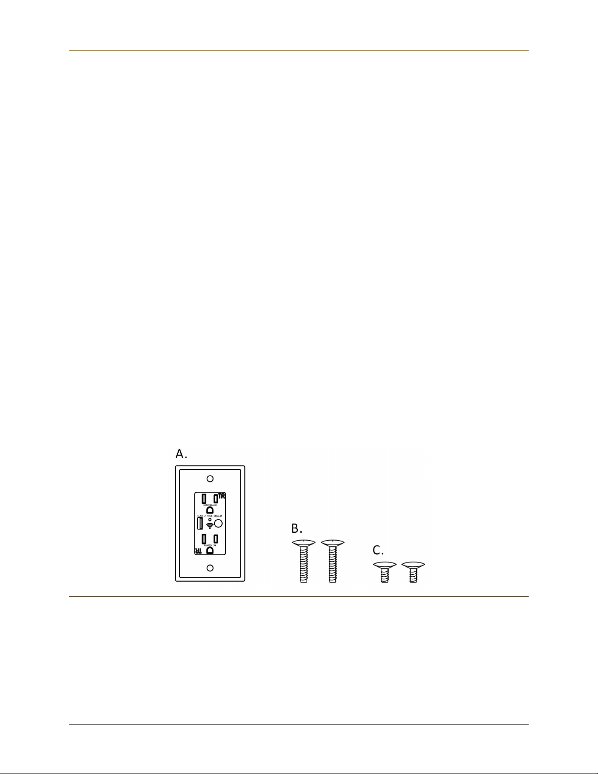
What’s In the Box .................................................................................................................... 3
Registering / Claiming the Device ........................................................................................... 4
User Interface ......................................................................................................................... 5
Push Button ........................................................................................................................ 5
Status Indicators ................................................................................................................. 6
Attaching to the Network ......................................................................................................... 6
About LoRaWAN .................................................................................................................... 7
Terminology ............................................................................................................................ 7
Installation .................................................................................................................................. 8
Important Safety Notice .......................................................................................................... 8
Getting Ready ......................................................................................................................... 8
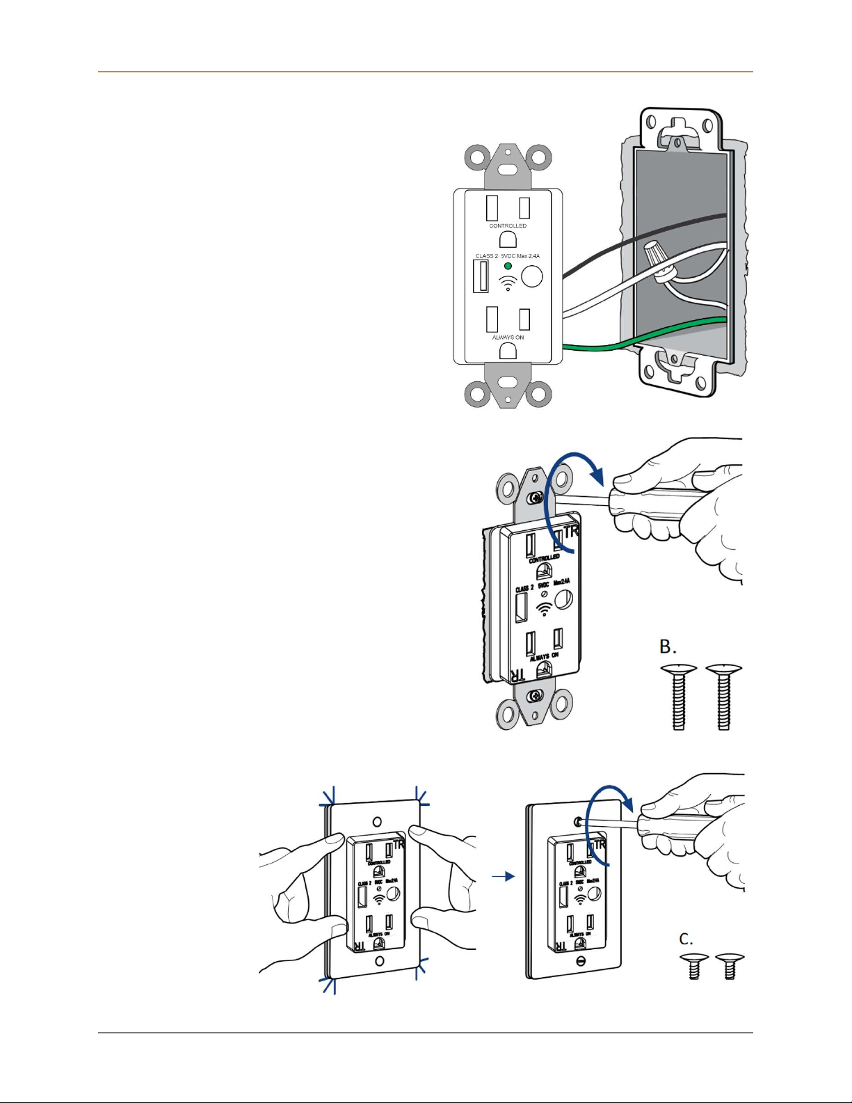
Outlet Installation .................................................................................................................... 8
Event Notifications and Reports ................................................................................................12
Reset Notifications .................................................................................................................13
Firmware Version ...................................................................................................................13
Configuration and Integration ....................................................................................................14
Specifications ............................................................................................................................15
Temperature Measurements and Thermal Heating ................................................................15
Dimensions ............................................................................................................................16
Ordering Information .................................................................................................................17
Communication Options .........................................................................................................17
Product SKU ..........................................................................................................................17
FCC Statement .........................................................................................................................19
© Copyright 2022 Codepoint Technologies, Inc.
All Rights Reserved

CS1030 Long Range Wall Receptacle Outlet – User Guide
Page 3
Getting Started
The CS1030 is a long-range, switchable, wall receptacle outlet supporting LoRaWAN or
Coralink wireless protocols. The 120V, 15-amp rated unit also provides a 2.4 Amp USB Type A
output. One device outlet can be controlled remotely or configured to turn on/off automatically
with built-in scheduler, while the other outlet is always on. The CS1030 supports advanced
scheduling capabilities including dynamic sunrise or sunset alarms, repetitive alarms, and
advanced programmable schedule triggers that can be initiated by LoRaWAN.
Ideal for smart home / smart building / smart city applications the device improves efficient
energy management and enhanced safety and security. Control lighting and equipment from
very long distances supporting a wide variety of public and private LoRa networks.
The outlet can be configured to monitor temperature supporting real-time measurements,
statistics, and threshold notifications.
What’s In the Box
The standard CS1030 single wall outlet package includes:
A. In-wall receptacle LoRaWAN compatible outlet: U.S. standard AC output rated for
100-120VAC
B. Cross Head Screw (M3)(2)
C. Slotted Head Screw (M3)(2)
Figure 1 - Items included in the C1030 package

CS1030 Long Range Wall Receptacle Outlet – User Guide
Page 4
Registering / Claiming the Device
The outlet is easily registered or claimed by scanning the QR claim key found on the side of the
outlet or on a removable sticker adhered to the front. Please consult your IoT application
provider for details on scanning the claim key and registering the device with your account.
Figure 2 – CS1030 QR claim key simplifies device registration and activation.
Once the device is registered or claim. The application provider will have secure access to the
device identity information, which will allow provisioning the device on any supported LoRaWAN
network.

CS1030 Long Range Wall Receptacle Outlet – User Guide
Page 5
User Interface
The CS1030 user interface is shown in the figure below.
Figure 3 – Performing Network or Factory Reset on the Wall Outlet
The device provides one switched outlet and one always-on outlet, a 2.4A (5V) USB charger, an
LED Indicator, and a push button.
Push Button
The Status LED on the front of the CS-1030 indicates the following status:
Action Description
One (1) quick press Default toggles the switched outlet on/off.
Two (2) quick presses Default turns on switched outlet for three minutes
Press and hold > 10 seconds
Network Reset
Press and hold the SET button for 10 seconds, but less than 25,
then release. The device will reset all LoRaWAN Settings, which
does not affect device operation or configuration.
Press and hold > 25 seconds
Factory Reset
Press and hold the SET button for > 25 seconds, then release.
The device will reset all parameters to factory defaults.
Following reboot, a Factory Reset event uplink (confirmed) will
be sent upon rejoining the LoRaWAN network.

CS1030 Long Range Wall Receptacle Outlet – User Guide
Page 6
Figure 4 – CS1030 LED Status Indicators
Status Indicators
The Status LED on the front of the CS-1030 indicates the following status:
LED Status
Blinking on/off (1sec interval) Not Joined to LoRa Network
On Switchable Outlet On (energized)
Off Switchable Outlet Off (de-energized)
Attaching to the Network
Once AC Power is connected, the CS1030 will automatically attempt to join the LoRaWAN
network automatically and the Status LED will blink continuously. After a while, the join
schedule will become less aggressive and up to 12 hours will elapse between join attempts. To
immediately force the CS1030 to join, perform a Network Reset operation.
To learn more about the capabilities of the CS1030, see Configuration and Integration.

CS1030 Long Range Wall Receptacle Outlet – User Guide
Page 7
About LoRaWAN
LoRaWAN is a low-power, secure, wide area (LPWAN) networking protocol designed to
wirelessly connect devices to the internet in regional, national, or global networks. To use the
CS1030 Wall Outlet, wireless connectivity to an internet connected LoRaWAN gateway is
required.
For more information about LoRa and LoRaWAN visit the LoRa Alliance webpage:
https://lora-alliance.org/.
Terminology
Message sent from the Wall Outlet to the network are referred to as “uplink messages” or
“uplinks”.
Messages sent to the Wall Outlet from the network are referred to as “downlink messages”
or “downlinks”.
Both uplink and downlink messages may be of either “confirmed” or “unconfirmed” type.
Confirmed messages are guaranteed to be delivered but will consume extra wireless
bandwidth and battery life. These mechanisms are analogous to TCP (confirmed) vs UDP
(unconfirmed) protocols used for IP networks.
Before a device, such as the CS1030 Wall Outlet can transmit messages using LoRaWAN it
must go through a “join” process. The Join process involves key-exchange with the cloud-
hosted network provider (The Things Network, Helium, etc.) and is defined in the LoRaWAN
protocol standard. If connectivity is lost due to RF interference, power loss or other
temporary internet outages, the device will need to rejoin the network prior to being able to
transmit messages. This process happens automatically but is managed in a power-efficient
manner and may take significant time depending upon network congestion and availability.

CS1030 Long Range Wall Receptacle Outlet – User Guide
Page 8
Installation
Important Safety Notice
If you are not comfortable working with 120V electrical wiring, please consult or hire
a qualified electrician. Turn off circuit(s) at the breaker or fuse panel and confirm
there is no voltage in the box before starting the installation (there may be multiple live circuits
within the switch box). Failure to use best electrical safety practices can result in injury or death!
All wiring connections must be made after the power is turned off to avoid personal injury and/or
damage to the outlet.
In-wall Outlet is designed and intended for indoor use only!
Total 15-amp maximum current. (Refer to the equipment or light bulb/fixture specifications if
in doubt).
Outlet is designed and intended only for permanently installed fixtures, and in accordance
with the national and local electrical codes and regulations of the United States or Canada,
as applicable
Getting Ready
Please ensure that the following equipment and electrical requirements are met before installing
the outlet.
Existing wall outlet replacement or new box with wiring ready has three wires: line (black),
neutral (white), ground (green).
At least two (2) inches of box depth is required (2 1/8” deep electrical boxes are typical).
Tools: you will need a Phillips screwdriver, flat-head screwdriver, wire strippers, and
voltage tester.
Outlet Installation
Turn off Circuit(s) at the breaker or fuse panel and confirm there is no
voltage in the electrical box before starting installation (there may be
multiple live circuits within the switch box).
Unscrew and remove the outlet plate; then use a voltage tester to
confirm the circuit is dead

CS1030 Long Range Wall Receptacle Outlet – User Guide
Page 9
Unscrew the outlet from the
electrical box and pull it out with the
wires still attached.
Three wires will be attached to the
outlet: an incoming line (hot) wire,
which is black; a neutral wire, which
is white; and a grounding wire, which
is green or bare typically copper.
There may be other wires in the box,
but you should only be working with
the wires connected directly to the
outlet
Compare your new outlet with
the one you are replacing to find
the corresponding locations for
the electrical screw connectors.
With the power off, transfer the
wires one at a time, matching
the same color to the
appropriate locations on the new
outlet.
Connect the first wire, unscrew the
associated screw terminal on the In-
Wall Outlet
Before Connecting, ensure about
½ inch of the wire is exposed.
Strip off excess shielding as
necessary
Insert the wire into the terminal
Tighten the screw terminal
Gently tug on the wire to ensure
a tight connection

CS1030 Long Range Wall Receptacle Outlet – User Guide
Page 10
Gently push the new, wired outlet back into
the electrical box and screw it in place.
Secure the outlet to the box with the two screws.
Snap on the plate and affix with the provided
screws.

CS1030 Long Range Wall Receptacle Outlet – User Guide
Page 11
Turn on the power.
If installed correctly, the outlet LED indicator should be blinking
slowly indicating that it has not joined. If the device is not yet
registered. Follow the procedures discussed in Section
Registering / Claiming the Device.
If the outlet was previously registered, press the push button
quickly to activate the switched outlet. The status indicator
should be green.
Press the push button again to turn off the switched outlet.
CS1030 Wall Outlet installation is complete and is now ready for
use and/or additional configuration.

CS1030 Long Range Wall Receptacle Outlet – User Guide
Page 12
Event Notifications and Reports
The CS1030 Wall Outlet has the following event notifications:
Outlet Socket Notifications:
Outlet ON (energized) – The outlet is powered on (default enabled)
Outlet OFF (de-energized) – The outlet is powered off (default enabled)
Additionally, statistics can be enabled to report aggregate outlet socket event activity:
ON Counter (how many times socket has been switched on)
OFF Counter
Current ON or OFF time duration (current state of the switch)
Min/Max ON Duration
Min/Max OFF Duration
This device includes temperature measurement capabilities. If your application supports the
Temperature API, the following events & statistics are available:
Temperature Event Notifications:
Temperature value greater than or less than specified value
Temperature relative change (positive or negative or both) exceed specified threshold
Temperature Statistics:
Min Temperature
Max Temperature
Average Temperature
Temperature Variance (take square root to get standard deviation)
Samples takes in last period
All Statistics are stored in non-volatile memory and will persist through a power outage. Both the
statistic reporting and alarms can be configured remotely by sending downlink messages.
The device has a periodic Heartbeat status message that is sent to maintain LoRaWAN network
connectivity. The default period for this message is 60 minutes and may be configured between
two (2) minutes minimum and 48 hours maximum.

CS1030 Long Range Wall Receptacle Outlet – User Guide
Page 13
Reset Notifications
FACTORY RESET uplink messages will be sent after rebooting.
Firmware Version
The firmware information can be retrieved via sending a downlink command. See Configuration
and Integration for details.

CS1030 Long Range Wall Receptacle Outlet – User Guide
Page 14
Configuration and Integration
The CS1030 supports the following settings and features, which are configured via downlink
messages.
Configuration Description Units Default
Set/Get State Turn the switch on/off N/A N/A
Set/Get Time Set the device current time and
location N/A N/A
Weekly Schedule Set one or more repeating weekly
schedules to turn the device on/off N/A N/A
Timers Set one or more timers that can be
triggered using a variety of events. N/A N/A
Heartbeat Interval Specifies the heartbeat message
uplink interval minutes 60
Statistics Interval How often the statistics are uplinked. minutes 0: disabled
Clear Statistics Downlink this message to clear the
stored statistics N/A N/A
LED Mode LED ON (Telemetry Only)
LED ON (Sensor and Telemetry) N/A LED ON (Device
and Telemetry)
Notification Confirm
/ Unconfirmed
Setting
If set to true, notifications are
confirmed uplink messages. Set to
false to uplink without confirmation.
N/A CONFIRMED
MESSAGES
Notification Enable
Enable or Disable notifications. If
disabled, the device operates as a
counter / statistic only device.
N/A enabled
Firmware Version Downlink this message to retrieve the
firmware information N/A N/A
For information on decoding and encoding the outlet messages please visit the product page at
Cora CS1030 Wall Outlet - Technologies.

CS1030 Long Range Wall Receptacle Outlet – User Guide
Page 15
Specifications
LoRa Protocols: Coralink Class C, LoRaWAN Class C
LoRa Frequencies: US (915 MHz)
ETL-Listed, FCC Approved
Color: White
One Power (on/off) control button
Green status Indicator LED
USB output: 5 Volts DC, 2.4 Amps Maximum
AC Input Power: 100-120VAC, 60Hz
AC Output Rating: 100-120VAC, 15 Amps Max. (Resistive)
Environmental:
o Operating Temperature Range: 14°F – 104°F (-10°C – 40°C)
o Operating Humidity Range: < 95% non-condensing
Intended for indoor use only
Temperature Measurements and Thermal Heating
All wall sockets can experience a minor thermal heating effect localized to the socket housing
due to impedance at the socket-to-plug connection and minimal airflow inside the fixture box.
This minor heating effect is normal in the operation of all electrical sockets and is not a safety
concern. The magnitude of localized heating increases as the current draw of the connected
load increases.
The temperature sensor of the CS1030 is located inside the socket-housing. Therefore, the
temperature measurements obtained from the CS1030 should be considered a rough estimate
of ambient temperature around the unit. Especially when installed indoors, the CS1030
temperature readings may often be higher than expected due to localized thermal effects from
connected loads on either the always on-socket or the LoRaWAN controlled socket.

CS1030 Long Range Wall Receptacle Outlet – User Guide
Page 16
Dimensions

CS1030 Long Range Wall Receptacle Outlet – User Guide
Page 17
Ordering Information
Communication Options
Prior to ordering, determine the communication requirements:
Application Protocol: Untethered XMF or CP-Flex OCM
Network Protocol: LoRaWAN or Coralink
Operating Region and Frequency: US915, EU868, CN470 (others available upon
request)
Network Provider: TTN, Helium, Chirp stack, etc.
Product SKU
When placing an order use the following SKU structure to determine the specific version, profile,
hardware revision, and packaging needed for the application.
The specification below details the SKU fields and character length.
[id: 6]-[version:2]-[Profile:5]-[Packaging:2]
The fields are defined as follows.
Field name Character
Length
Description
ID 6 Device six (6) character identification code, Available options:
CS1030 – Revision A Cora Wall Receptacle Outlet
Version 2 Device version specification identifying one or key variations that
differentiate this version of the component relative to others. Available
options:
UL – Untethered XMF Application / LoRaWAN protocols
CL – Cora OCM / LoRaWAN protocols
CC – Cora OCM / Coralink protocols
Profile 5 Profile code specifies a configuration that may be unique for an
implementation. Available options:
US9HT – U.S. 915 MHz Region supporting Helium, TTN sub-band 2.
EU8ST – Europe 868 MHz region standard configuration
CN4EZ – China 470 MHz region Easylinkin (Link ware) network
configuration

CS1030 Long Range Wall Receptacle Outlet – User Guide
Page 18
Other profiles are available upon request.
Packaging 2 Packaging configuration. This code determines the packaging format for
the device. Available standard options:
00 – Standard reseller packaging.
0X – Custom packaging option. Contact Codepoint for further
information.
Example SKUs:
CS1030-UL-US9HT-00 – Wall Outlet for U.S. region, untethered, supporting Helium and
TTN sub-band 2.
CS1030-UL-EU8ST-00 – Wall Outlet for Europe region, untethered, standard configuration.
CS1030-CL-US9HT-00 – Wall Outlet configured for Cora OCM and CP-Flex cloud stack
integration, Supports OCM V2 protocol specifications.

CS1030 Long Range Wall Receptacle Outlet – User Guide
Page 19
FCC Statement
This equipment has been tested and found to comply with the limits for a Class B digital device,
pursuant to part 15 of the FCC Rules. These limits are designed to provide reasonable
protection against harmful interference in a residential installation. This equipment generates,
uses, and can radiate radio frequency energy and, if not installed and used in accordance with
the instructions, may cause harmful interference to radio communications. However, there is no
guarantee that interference will not occur in a particular installation. If this equipment does
cause harmful interference to radio or television reception, which can be determined by turning
the equipment off and on, the user is encouraged to try to correct the interference by one or
more of the following measures:
Reorient or relocate the receiving antenna
Connect the equipment into an outlet on a circuit different from that to which the receiver is
connected
Increase the separation between the equipment and receiver
Consult the dealer or an experienced radio / TV technician for help
This device complies with part 15 of the FCC Rules. Operation is subject to the following two
conditions:
1. This device may not cause harmful interference
2. This device must accept any interference received, including interference that may cause
undesired operation.
Any changes or modifications not expressly approved by the party responsible for compliance
could void the user’s authority to operate the equipment.
Note: The manufacturer is not responsible for any radio or TV interference caused by
unauthorized modifications to this equipment. Such modifications could void the user’s authority
to operate the equipment.
FCC RF radiation exposure statement
This equipment complies with FCC RF radiation exposure limits set forth for an uncontrolled
environment. This device and its antenna must not be co-located or operating in conjunction
with any other antenna or transmitter. “To comply with FCC RF exposure compliance
requirements, this grant is applicable to only Mobile Configurations. The antennas used for this
transmitter must be installed to provide a separation distance of at least 20 cm from all persons
and must not be co-located or operating in conjunction with any other antenna or transmitter.”
Table of contents
Other CORA Accessories manuals
Popular Accessories manuals by other brands

König & Meyer
König & Meyer 80359 Assembly instructions

daviteq
daviteq WS433-DI user guide

PCB Piezotronics
PCB Piezotronics JM353B14 Installation and operating manual

A-solar
A-solar AL-360 manual

Waterpik
Waterpik Waterflosser WP-810 instruction manual

Jupiter Avionics
Jupiter Avionics eqJAC-001 Installation and operating manual