manuals.online logo
Brands
  1. Home
  2. •
  3. Brands
  4. •
  5. CCTVMule
  6. •
  7. Media Converter
  8. •
  9. CCTVMule HD MULE 2 User manual

CCTVMule HD MULE 2 User manual

It’s the easy way to add extra
cameras to an existing installation!
*as per instructions
“Send 2 HD Video Signals Or
Data Down 1x Co-ax Cable...”
HD Mule2 Instructions
Order Code: MULE102
Instructions - Instructions - Instructions
Instructions
...with a
1
x
R
G
5
9
O
U
T
&
D
A
T
A
O
U
T
2
x
V
i
d
e
o
I
n
HD
MULE
2
Compatible with
TVI, CVI, AHD
&Analogue
• TVI, CVI, AHD & Analogue
• Up to 2 videos down co-ax*
• Data combiner*
• Wall mount design
• Up to 500mtrs*
• Easy to setup
o
r
1
x
v
i
d
e
o
i
n
Scan the QR code for
more information or
visit CCTVmule.com
Need a little extra help? email: [email protected]
HD Mule Instructions
3
On installations where you have only one co-ax cable installed, the HD Mule makes it
really easy to add extra cameras - it saves time, saves money & saves mess.
Perfect if you don’t have access to run any more cables, even data cables, underground.
The clever electronics of the MULE102 allow it to carry the RS485 data along the same RG59
Co-ax cable enabling the operator to monitor and control the system from a dierent location.
Using multi-signal technology the HDMule works with TVI, CVI, AHD and even analogue
cameras for maximum exibility.
Please Note - some HD cameras (TVI, CVI and AHD) use“up the co-ax” menu control, because
of how the HDMules work this “Co-axitron” will not work through the Mule, however on PTZ
and similar cameras you can use the Mule’s RS485 transmission to operate the camera.
Higher resolutions than the stated ones may work on shorter cable lengths but with so
many variables involved like camera technology, distance, cable quality and frame rate, the
maximum resolutions are stated for guidance. On most HD cameras you can adjust the output
to suit and we suggest setting this to 2MP.
Carries multiple HD video signals - even data
- down ONE RG59 cable!
Connections - Transmitter (Tx)
Connections - Receiver (Rx)
P
1 IN 2 IN
VID/DATA VID
DC 12V VIDEO OUT
BNC video input from camera
Power LED shows
power is connected
BNC video input or RS485 data output
depending on operation mode BNC video out to Rx
2.1mm 12V DC socket
VIDEO IN
1 OUT 2 OUT
P
VID/DATA VID
DC 12V
BNC video in from Tx Power LED shows
power is connected
BNC video output or RS485 data input
depending on operation mode
BNC video output to DVR2.1mm 12V DC socket
For further information visit: www.cctvmule.com
HD Mule Instructions
4
The HD Mule 2 has the following 2 operation modes...
Operation Modes
Mode
12 Video signals down 1 co-ax cable
V1
V1
V2
V2
12V DC
12V DC
HD Mule 2
Tx
HD Mule 2
Rx
1x RG59 co-ax cable
V1, V2 in this direction
Mode
21 Video signal in one direction, 1 RS485 signal in the opposite direction
V2
V2
12V DC
12V DC
HD Mule 2
Tx
HD Mule 2
Rx
1x RG59 co-ax cable
Data
down V1
Data
down V1
RS485 Data
The HD Mule 2 can also be used as a combiner to view and control a PTZ down 1 co-ax cable
V2 in this direction
CON380
To connect RS485 data to a BNC socket you need a
BNC to terminal adapter like the CON380. These clever
adapters convert a positive and negative terminal
connection into a BNC plug and work either way.
CON380
HD Mule Instructions
Installation
1. Ensure that the HD or analogue camera is connected to
the Mule Transmitter (marked Tx). The Mule units are not
waterproof and must be installed in water proof boxes if
installed outdoors.
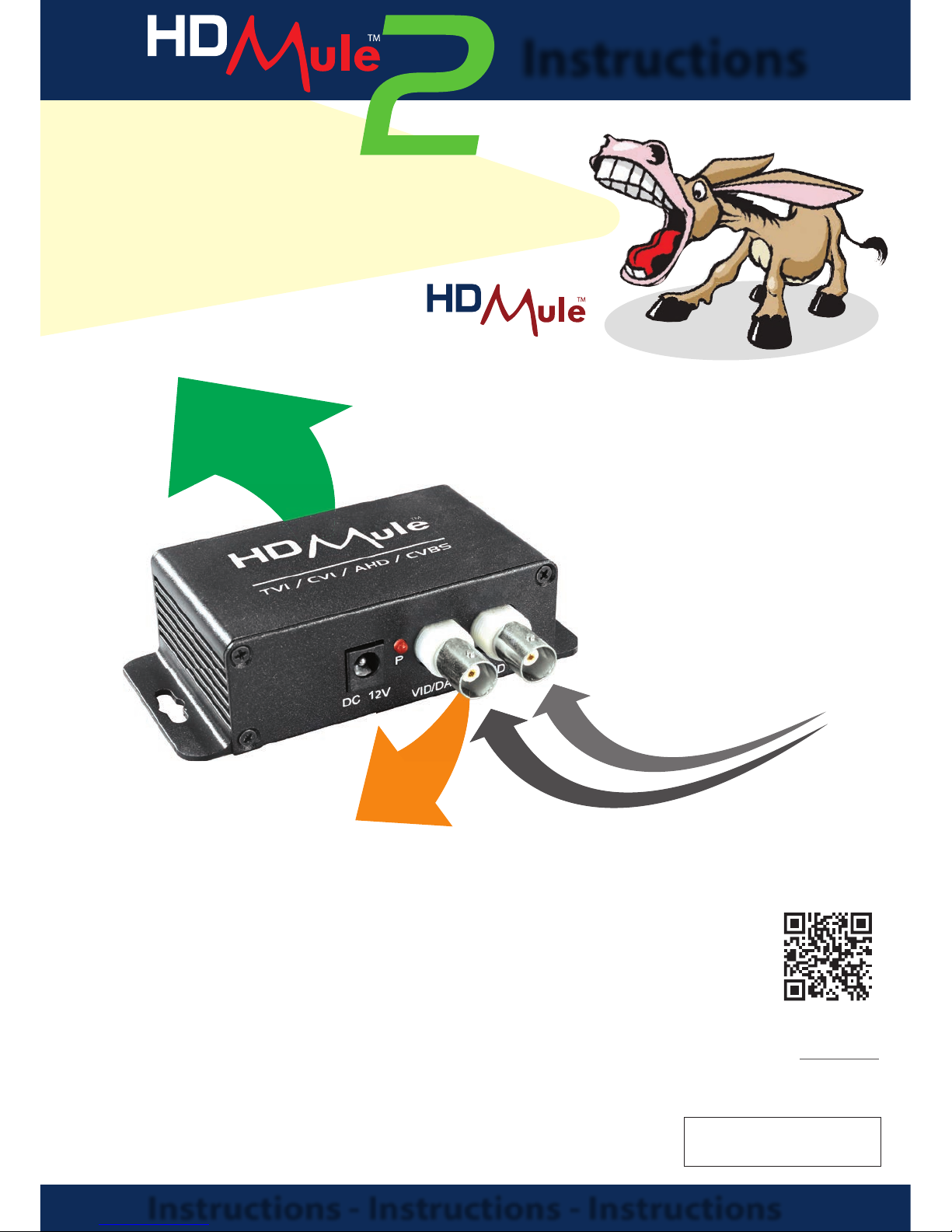
2. Connect the camera video feeds to the BNC connections
marked IN 1 and IN 2 on the Mule Tx. If using the unit
as a combiner for RS485 data transmission, connect to IN 1
using a BNC to terminal adapter (CON380) at each end.
3. Take a coax cable from the single video out BNC
connection on the back of the transmitter to the single
BNC in connection on the Mule Receiver. Connect BNCs
from the respective video outputs on the Mule Receiver to
a compatible DVR or suitable equipment.
4. If using the RS485 connection, only one video stream can
be used as well. The RS485 works in the alternate direction
to the video. i.e. from receiver to transmitter.
Powering The Units
The MULE102 units are powered with a 12V DC input connected to the 2.1mm DC socket. The
Transmitter requires a minimum of 60mA and the Receiver requires a minimum of 275mA. To
power the units we recommend 12V DC PSU supplying no less than 500mA to each unit.
© Copyright CCTVMule 2018
For more information email: [email protected] or visit: www.cctvmule.com
Transmitter (Tx) Receiver (Rx)
Compatibility TVI (3MP) / CVI / AHD / Analogue
Video
Connection
2x BNC Inputs /
1x BNC Output
1x BNC Input /
2x BNC Outputs
Data Connection BNC Socket
Power 12V DC (PSUs Required)
Consumption 60mA 275mA
Max Transmission 500m (Standard RG59)
Operating
Temperature -30°C ~ +50°C
Case Material Aluminium Alloy
Weight 67.5g
Dimensions 64 x 42 x 23mm
Technical Specification
All specications are approximate. We reserve the right to change any product
specications or features without notice. Whilst every eort is made to ensure
that these instructions are complete and accurate, CCTVMule cannot be held
responsible in any way for any losses, no matter how they arise, from errors or
omissions in these instructions, or the performance or non-performance of the
equipment that these instructions refer to.
WEE/CG0783SS
This symbol on the products and/or accompanying documents
means that used electronic equipment must not be mixed with
general household waste. For treatment, recovery and recycling
please return this unit to your trade supplier or local designated
collection point as dened by your local council.

This manual suits for next models

1

Popular Media Converter manuals by other brands

TR-Electronic CMS582M-4096/4096 IOL DMS 14H7 KRF Assembly instructions

TR-Electronic

TR-Electronic CMS582M-4096/4096 IOL DMS 14H7 KRF Assembly instructions

Korenix JetCon 2301S user manual

Korenix

Korenix JetCon 2301S user manual

StarTech.com ET91000LCOAM manual

StarTech.com

StarTech.com ET91000LCOAM manual

Alesis AI-3 Reference manual

Alesis

Alesis AI-3 Reference manual

Caton Vpro 5100 user guide

Caton

Caton Vpro 5100 user guide

Cypress CSC-5500 Operation manual

Cypress

Cypress CSC-5500 Operation manual

H&B TX-100 Installation and instruction manual

H&B

H&B TX-100 Installation and instruction manual

Bolin Technology D Series user manual

Bolin Technology

Bolin Technology D Series user manual

IFM Electronic Efector 400 RN30 Series Device manual

IFM Electronic

IFM Electronic Efector 400 RN30 Series Device manual

GRASS VALLEY KUDOSPRO ULC2000 user manual

GRASS VALLEY

GRASS VALLEY KUDOSPRO ULC2000 user manual

Linear Technology DC1523A Demo Manual

Linear Technology

Linear Technology DC1523A Demo Manual

Lika ROTAPULS I28 Series quick start guide

Lika

Lika ROTAPULS I28 Series quick start guide

Weidmuller IE-MC-VL Series Hardware installation guide

Weidmuller

Weidmuller IE-MC-VL Series Hardware installation guide

Optical Systems Design OSD2139 Series Operator's manual

Optical Systems Design

Optical Systems Design OSD2139 Series Operator's manual

Tema Telecomunicazioni AD615/S product manual

Tema Telecomunicazioni

Tema Telecomunicazioni AD615/S product manual

KTI Networks KGC-352 Series installation guide

KTI Networks

KTI Networks KGC-352 Series installation guide

Gira 0588 Series operating instructions

Gira

Gira 0588 Series operating instructions

Lika SFA-5000-FD user guide

Lika

Lika SFA-5000-FD user guide

manuals.online logo
manuals.online logoBrands
  • About & Mission
  • Contact us
  • Privacy Policy
  • Terms and Conditions

Copyright 2025 Manuals.Online. All Rights Reserved.