I-53I-53
The I-53 is an automatism-clock for hour signals, with an independent activation for hours, and others thanks to
two relays. It could be used during 24 Hours or only during the day with two different time-tables. You could
introduce two connection times for fours and other.
It includes manual function to activate outputs when you wish.
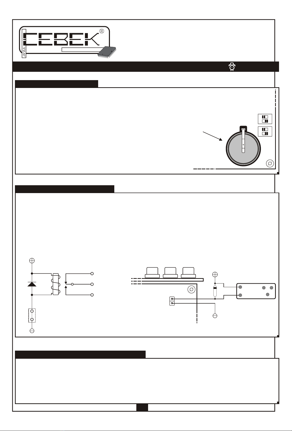
It also includes signal led, hourly visualisation, keyboard, battery, front panel, connection terminals to make
OPERATING.
OPERATING.
2
TIMERS I-53I-53
Ref. Full9809
TIMER FOR CLOCK AND BELL.
TECHNICAL CHARACTERISTICS.
Voltage. ..........................................................................................12 V. DC.
Minimum Consumption. ................................................................50 mA.
Maximum Consumption. ...............................................................150 mA.
Minimum Connection Time for Hours and Others Relays. ............ 0.5 sec.
Battery. .......................................................................................... CR-20 (3 V.)
Protection against polarity inversion . ............................................ Yes.
Maximum Admissible Load. ...........................................................3 A.
Maximum Connection Time for Hours and Others relays. ............ 1 sec.
Hour Format. ................................................................................. 24 H.
Displays. ........................................................................................ 4 x 0.5“ Displays (13.5 mm.) and led.
POWER SUPPLY : The I-53 circuit had to be supplied by a 12 VDC power supply perfectly stabilised and we suggest
you to not use rectifier or power supply not stabilised to avoid to damage the module.
Then, we recommended you the FE-2 power supply which has been developed to perfectly answer to the circuit
needs. Connect the positive of the power supply to the positive terminal indicated in the wiring map, then
connect also the negative of the power supply to the negative terminal indicated in the circuit. Verify that the
assembly has been correctly done.
OPERATING : The I-53 module is an automatism to imitate the operating Bell clock, indicating hours and others.
Then, the hour relay will be activated each hour and the second relay will be activated each 15 minutes. The
module had been designed on a quartz oscillator basis, guaranteeing a maximum exactitude. It also includes
different options offering it a wide applications range.
HOW TO ADJUST HOUR : The module had a clock to control the automatism and to visualise the hour. Before to
activate the module in its definitive application, you have to adjust it. Then, you have to maintain pressed the
"enter" push button placed in the front of the module till the LD1 led will light on. At this moment both hour
displays will intermittently light and minutes display will be fixed.
When you are adjusting the hour, do not forget that you only modify fix displays because intermittent display are
in stand by. Then, you could firstly adjust minutes displays pressing on "up" and "Down" push buttons to increase or
decrease the number. If you maintain pressed any of these two button, the change will be quickly done.
Once minutes adjusted, you have to press the "enter" button to fix hours displays and intermittent minutes
displays. Then, you could adjust wished hours pressing "up" and "down" buttons.
Therefore if you press the "enter" button you stop the adjustment and LD1 led will light off.
OUTPUTS TIMING : At each pulse, hours and others outputs could be adjusted according to possible connection
times : 0,5 and 1 sec. See the drawing Nº1 to find the selector indicated as INT-1 and two switches in OFF position
which corresponding outputs offer 0,5 sec. Impulses.
Then, if you place these switches in ON position, the corresponding output will offer 1 sec. Impulses.
1 control the configuration of the module to operate in 24 Hours or daily mode. If you place this switch in OFF
position, the I-53 module will generate impulses during 24 Hours, but if you place it in ON position, the module
only generate impulses during several hours a day (that you could configure thanks to the switch Nº2).
The switch Nº2 control the operating hours to allow to the module generate impulses for the daily mode. If you
place this switch in OFF position, the operating margin is established between 8 :00 A.M and 22 P.M. If you place
it in ON position, the margin will established between 6 :00 A :M and 24 Hours.
MANUAL CONTROL : In spite of the automatic operating mode, and independently, the I-53 module allows at
any time to establish a manual connection for hours and others. To activate this operation you have to maintain
pressed the button corresponding to the manual control.
TO ACTIVATE BOTH OUTPUTS AT THE SAME TIME : The circuit allows to activate both relay at the same time using
manual or automatic connections. To activate this option, you have to place the switch INT-3 in ON position. If
you wish a separate activation for hours and others, you have to place the switch in OFF position.
OPERATING TIME : The module, as we have previously explicated, offer two different
impulses. The I-53 module incorporates a selector to configure it in continuous hours during
24 hours, or daily hours (only during the day) with two time margins to select.
Seeing the drawing Nº1, the selector is indicated as INT-2 and you could find 2 switches.
The switch Nº
1
Module Front Panel
DownUp
Manual Control Hours Minutes
Hour Adjustment
LD1
Enter
H
Q’
1
ON
2
INT-2
1
ON
2
INT-1
Fig. 1
1
ON
2
INT-2
8 - 22 H.
1
ON
2
INT-2
Daily Mode
1
ON
2
INT-2
24 H. Mode.Daily Mode.
1
ON
2
INT-2
Daily 24H/ Mode
Manual Control
H
Q’
OthersHours
INT-3
Independent Outputs
1
ON
INT-3
Joint Outputs
1
ON
ELECTRONIC CIRCUITS
1
ON
2
INT-1
0.5 sec.1 sec.
1
ON
2
INT-1
Hours Timming
1
ON
2
INT-1
0.5 sec.1 sec.
1
ON
2
INT-1
Others Timming.
6 - 24 H.